horn AUDI RS7 SPORTBACK 2014 Owners Manual
[x] Cancel search | Manufacturer: AUDI, Model Year: 2014, Model line: RS7 SPORTBACK, Model: AUDI RS7 SPORTBACK 2014Pages: 292, PDF Size: 73.56 MB
Page 11 of 292
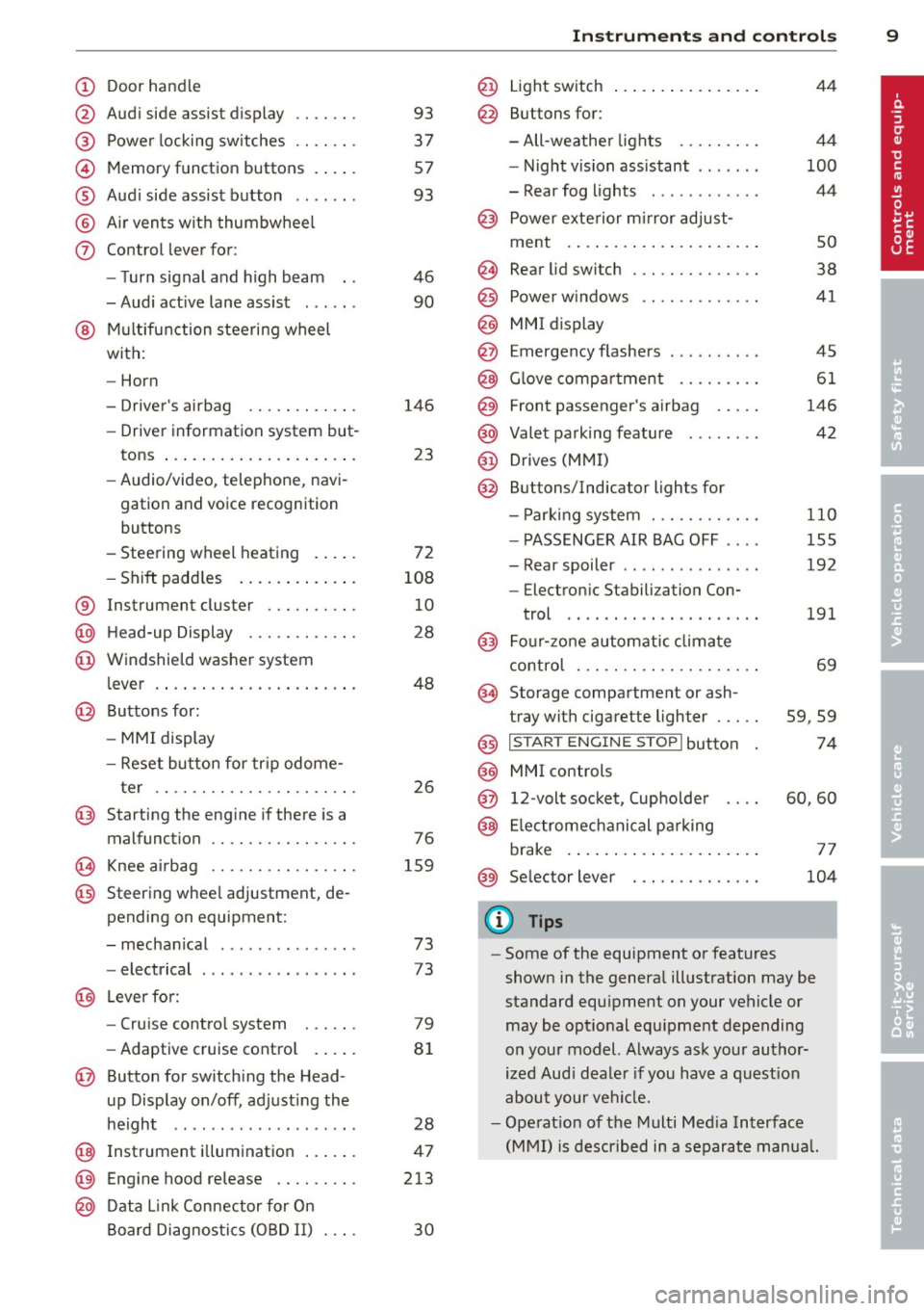
(!) Door handle
@
®
©
®
®
(j)
Audi side assist d isplay
Power locking sw itches
Memory function buttons . ... .
Aud i side assist button .. .. .. .
A ir vents with thumbwheel
Control lever for :
- T urn signal and high beam
- Audi act ive lane assist . .. .. .
@ Mu ltifunction steering wheel
with:
- Horn
- Driver's airbag
- Driver information system but-
tons ... ..... ....... ... .. .
- Audio/video , telephone, navi
gation and voice recognition
buttons
- Steering wheel heating . ... .
- Shift padd les ..... ... .. .. .
® Instrument cluster ..... .. .. .
@ H ead-up Display ....... .. .. .
@ Windsh ield washer system
l ever .... .... ...... ... .. .. .
@ Buttons for :
- MM I display
- Reset button for tr ip odome-
ter .. .. ............. .... .
@ Starting the eng ine if there is a
malfunction
~ Knee airbag ........... .... .
@ Steering whee l adjustment, de
pending on equipment:
- mechanical . ............. .
- electrical
@ Leverfo r:
- Cru ise contro l system
- Adaptive cruise cont ro l .. .. .
@ Button for switch ing the Head
up Display on/off , adjusting the
h eight .. ................ . .
@ Instrument illuminat ion ... .. .
@ Eng ine hood release .... .. .. .
@ D ata Link Connector for On
Board Diag nos tics ( OBD II) . .. .
93
37
57
93
46
90
146 23
72
108 10
28
48
26
76
159
73
73
79
8 1
28
47
213
30
In strument s and control s 9
@ Light switch ..... . .. .. ..... .
@ Buttons for :
- All -weathe r lights
- Night vision assistant . .. ... .
- Rear fog lights . .......... .
@ Power exterior mirror adjust-
ment . ... .... .. . .. .. ..... .
@ Rear lid switc h ............. .
@) Power w indows .... ........ .
@ MMI display
@ Emergency flashers
@ G love compar tment ........ .
@ Front passenger's airbag .... .
@ Valet parking feature ....... .
@ Drives (MMI)
@ Buttons/Indicator ligh ts for
- P arking system ........... .
- PASSENG ER AIR BAG OFF ... .
- Rear spoiler .. .. . .. .... ... .
- E lectron ic Stabili zation Con-
trol .. .. .. .. .. . ... ...... .
@) Four-zone automatic climate
control . .. .. .. .. .. ........ .
@ Storage compartment or ash-
tray with cigarette ligh ter .....
@) I STAR T ENGIN E ST OPI button
@ MMI controls
@ 12-volt socket , (upholde r
@ Elec tromechanical pa rking
brake . ... .. .... . ... ...... .
@ Selector lever
(D Tips
44
4 4
100
44
so
38
41
45
61
146
42
110
155
192
191
69
59,59
74
60,60
77
104
- Some of the equipment or features
shown in the genera l ill ustration may be
standard equ ipment on your vehicle or
may be opt ional equ ipment depending
on you r model. Always ask your autho r
ized Aud i dea le r i f you have a quest ion
about your ve hicl e.
- Ope rat ion of the Multi Med ia Interface
(MMI) is described in a separate manua l.
Page 38 of 292
36 Openin g and clo sing
• Press button rfl (@ ) to lock the vehicle¢ &
in General description on page 34.
• Press button c:s (@ ) briefly to un lock the
rear lid.
• Push the red
IPANICI button( @) to activate
the panic function . The horn sounds and the
turn s ignals flash. Push the red
I PANIC I but
ton aga in to deact ivate the panic function.
If the vehicle is unlocked and no door, the rear lid or the hood is opened with in 60 seconds,
the vehicle locks itself again automatically .
This feature prevents the ve hicle from be ing
accidenta lly left unlocked ove r a long period
of time.
It depends on the sett ings in the MMI wheth
e r the enti re veh icle is un locked or on ly cer
tain doors ¢
page 35.
.&_ WARNING
Read and follow a ll WARNINGS¢ &. in
General description on page 34.
{D Tips
- In order to make sure the locking func
tion is working, you shou ld always keep
you r eye on the vehicle to make su re i t is
properly locked.
-
- Do not use the remote control if you are
i nside the car, o therwise you may unin
tentiona lly lock the vehicle, and then you
would set off the anti-theft alarm when
you try to start the engine or open a
door. In case this happens anyhow, push
the un lock button @.
- The vehicle can on ly be locked when the
se lector lever is in the P posit ion.
- Use the panic funct ion only i f you are in
an emergency situation.
Locking and unlocking with convenience
key
Appl ies to vehicles : wi th convenience key
The doors and the rear lid can be unlocked
and locked without operating the master key.
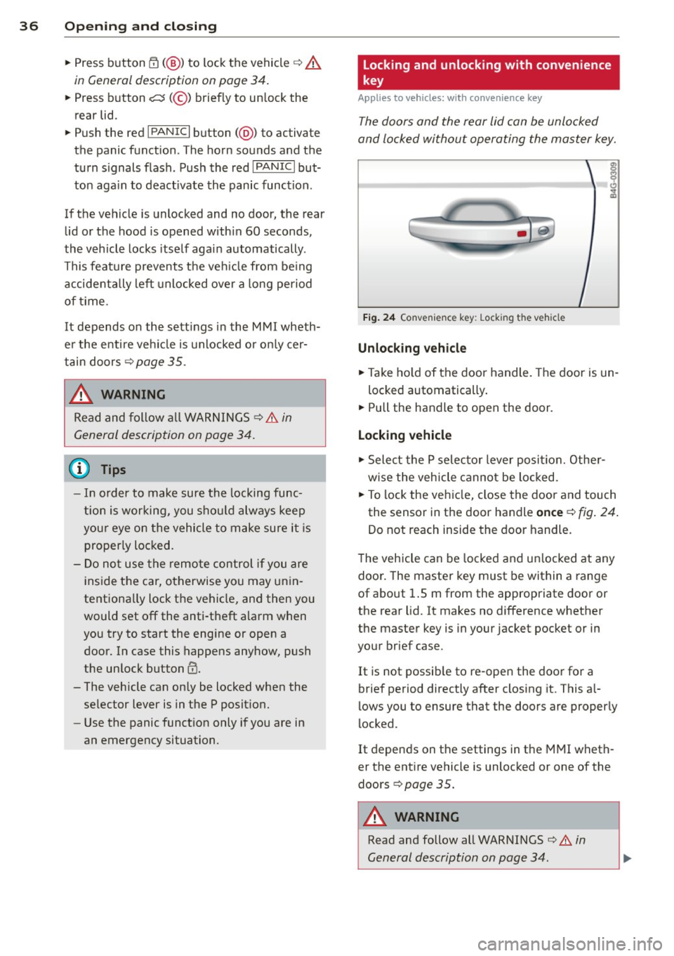
Fi g. 24 Co nve nienc e key: Lock ing the vehicle
Unlocking vehicle
• Take ho ld of the door handle . T he door is un-
locked automatically .
• Pull the handle to open the door.
Locking vehicle
• Select the P se lec to r lever posit ion. Othe r
w ise the vehicle cannot be loc ked.
• To lock the veh icle, close the door and touch
the sensor in the door handle
once ¢ fig. 24 .
Do not reach inside the door handle.
T he vehicle can be locked and un locked at any
door . The master key must be within a range
of about 1.5 m from the appropriate door or
the rear lid. It makes no difference whether
the master key is in your jacket pocket or in
your brief case.
It is not possib le to re-open the door for a
brief period directly after closing it. This a l
l ows you to ensure that the doors are properly
locked.
It depends on the settings in t he MMI wheth
er the ent ire vehicle is unlocked or one of the
doors ¢
page 35 .
.&_ WARNING ~ -
Read and follow all WARNINGS ¢.&. in
General description on page 34 .
Page 160 of 292
158 Airb ag sys te m
- Have the airbag system inspected by
your Audi dealer before transporting
anyone on the front passenger seat.
If the capacitive passenger detection sys
tem determines that the front passenger seat is empty, the frontal airbag on the
passenger side will be turned off, and the
P ASS ENGER AIR BA G OFF light w ill stay
on .
Repair, care and disposal of the airbags
Parts of the a irbag system are installed at
many different pla ces on your Audi . Installing,
removing, servicing or repairing a part in an
area of the vehicle can damage a part of an
airbag system and prevent that system from
working properly in a co llision.
There are some important things you have to know to make sure that the effectiveness of
the system will not be impaired and that dis
carded components do not cause injury or po l
lute the environment.
A WARNING
Improper care, servicing and repair proce
dures can increase the risk of personal in
jury and death by preventing an airbag from deploy ing when needed or deploying
an airbag unexpectedly:
- Never cover, obstruct, or change the
steering wheel ho rn pad or airbag cover
or the instrument pane l or modify them
in any way .
- Never attach any objects such as cup
holders or telephone mountings to the
surfaces covering the airbag uni ts.
- For cleaning the horn pad or instrument
pane l, use only a soft, dry cloth or one
moistened w ith plain water. Solvents or
cleaners co uld damage the airbag cover
or change the stiffness or strength of the
material so that the airbag cannot de
ploy and protect properly. -
Never repair, adjust, or change any parts
of the a irbag system.
- All work on the steering wheel, instru
ment panel, front seats or e lectr ica l sys
tem (including the installation of audio
equ ipment, cellu lar telephones and CB
radios, etc.) must be performed by a
qualified technic ian who has the training
and specia l equipment necessary.
- For any wo rk on the airbag system, we
strongly recommend that yo u see your
author ized Audi dealer or qualified work
shop.
- Never modify the front bumper or parts
of the vehicle body.
- Always make sure that the s ide airbag
can inf late without inte rfe rence:
- Never install seat covers or rep lace
ment upholstery over the front seat
backs that have not been specifically
approved by Audi.
- Never use additional seat c ushions that
cover the areas where the side a irbags
inflate.
- Damage to the orig inal seat covers or
to the seam in the area of the side a ir
bag module must a lways be repaired
immediately by an author ized Audi
dealer .
- The airbag system can deploy on ly once .
After an a irbag has been deployed, it
must be replaced w ith new replacement
pa rts des igned and app roved es pecially
for your Aud i mo del ve rsion. Replace
ment of comple te airbag systems or air
bag components must be performed by
qualified wor kshops only . Make sure that
any airbag service action is entered in
your Audi Warranty
& Maintenance book
let under
AIRBAG REPLACEMENT RE
CORD .
-For safety reasons in severe accidents,
the alternator and starter a re sepa rated
from the veh icle battery with a pyrotech
n ic circuit inte rrupte r.
- Work on the pyrotechnic circuit inter
rupter must only be performed by a
qualified technicians who have the
llll-
Page 262 of 292
260 Fuses and bulbs
Fuses and bulbs
Fuses
Replacing fuses
Fuses that have blown will have metal strips
that have burned through.
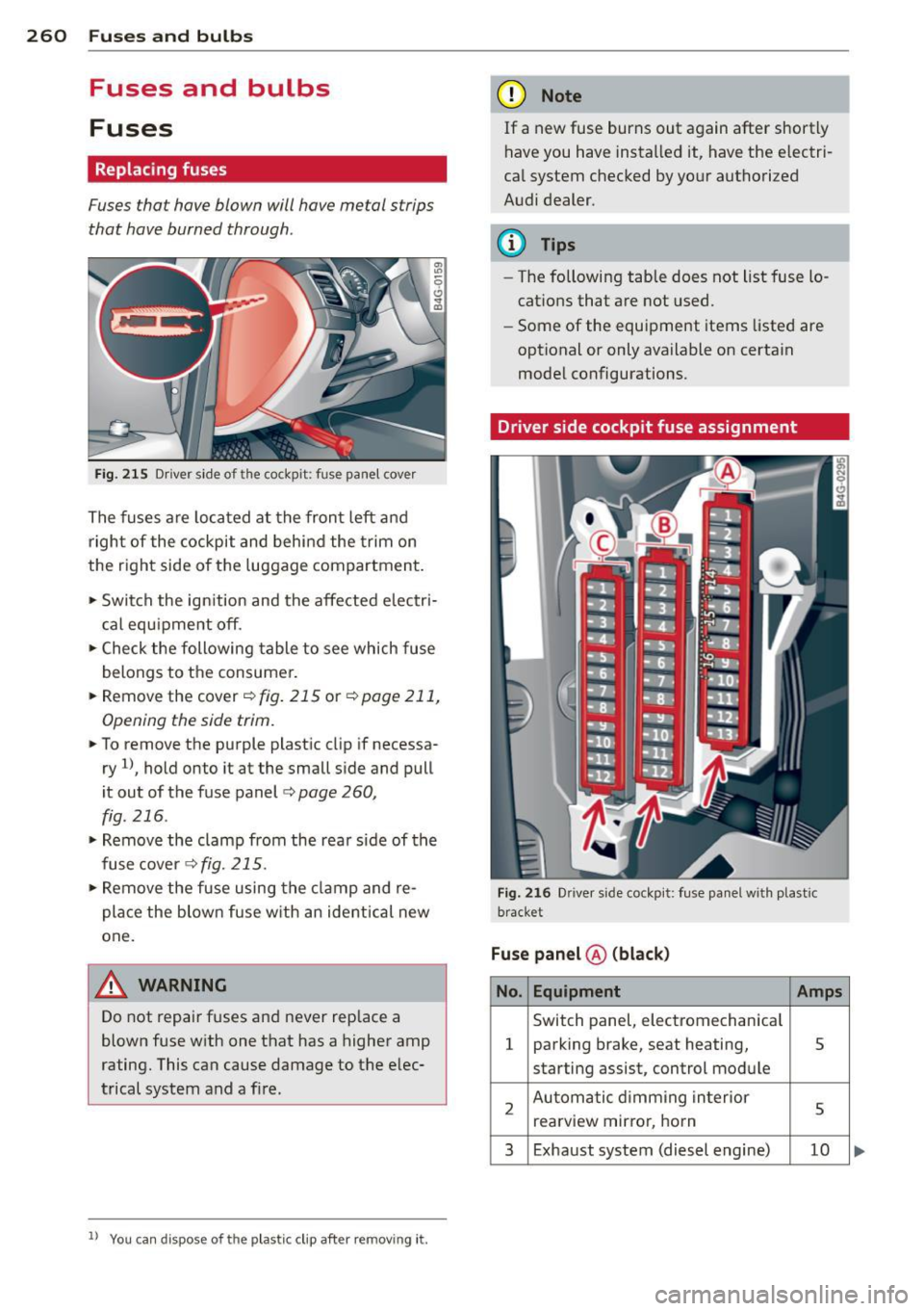
Fig. 215 Driver side of the cockpit: fuse panel cover
The fuses are located at the front left and
right of the cockpit and behind the trim on
the right side of the luggage compartment.
• Switch the ign ition and the affected electri
cal equ ipment off.
• Check the following table to see which fuse
belongs to the consumer.
• Remove the cover ¢
fig. 215 or¢ page 211,
Opening the side trim.
• To remove the purple plastic clip if necessa
ry
ll, hold onto it at the small side and pull
it out of the fuse panel
c:> page 260,
fig. 216 .
• Remove the clamp from the rear s ide of the
fusecover <>fig.
215.
• Remove the fuse using the clamp and re
pla ce the blown fuse w ith an ident ical new
one.
A WARNING
Do not repair fuses and never replace a
blown fuse with one that has a higher amp
rating. This can cause damage to the elec
trical system and a fire.
ll You can dis pose of the plastic clip after re moving it.
(D Note
If a new fuse burns out again after shortly
have you have installed it, have the electri
cal system checked by your authorized
Audi dealer.
(D Tips
-The following table does not list fuse lo
cations that are not used.
- Some of the equipment items listed are
optional or only available on certain
model configurations.
Driver side cockpit fuse assignment
Fig. 216 Dr ive r side cockpit: fuse panel with plastic
bracket
Fuse panel ® (black)
No. Equipment Amps
Switch panel, electromechanical
1 parking brake, seat heating, 5
starting assist, control module
2 Automatic dimming interior
5 rearview mirro r, horn
3 Exhaust system (diesel engine) 10
Page 263 of 292
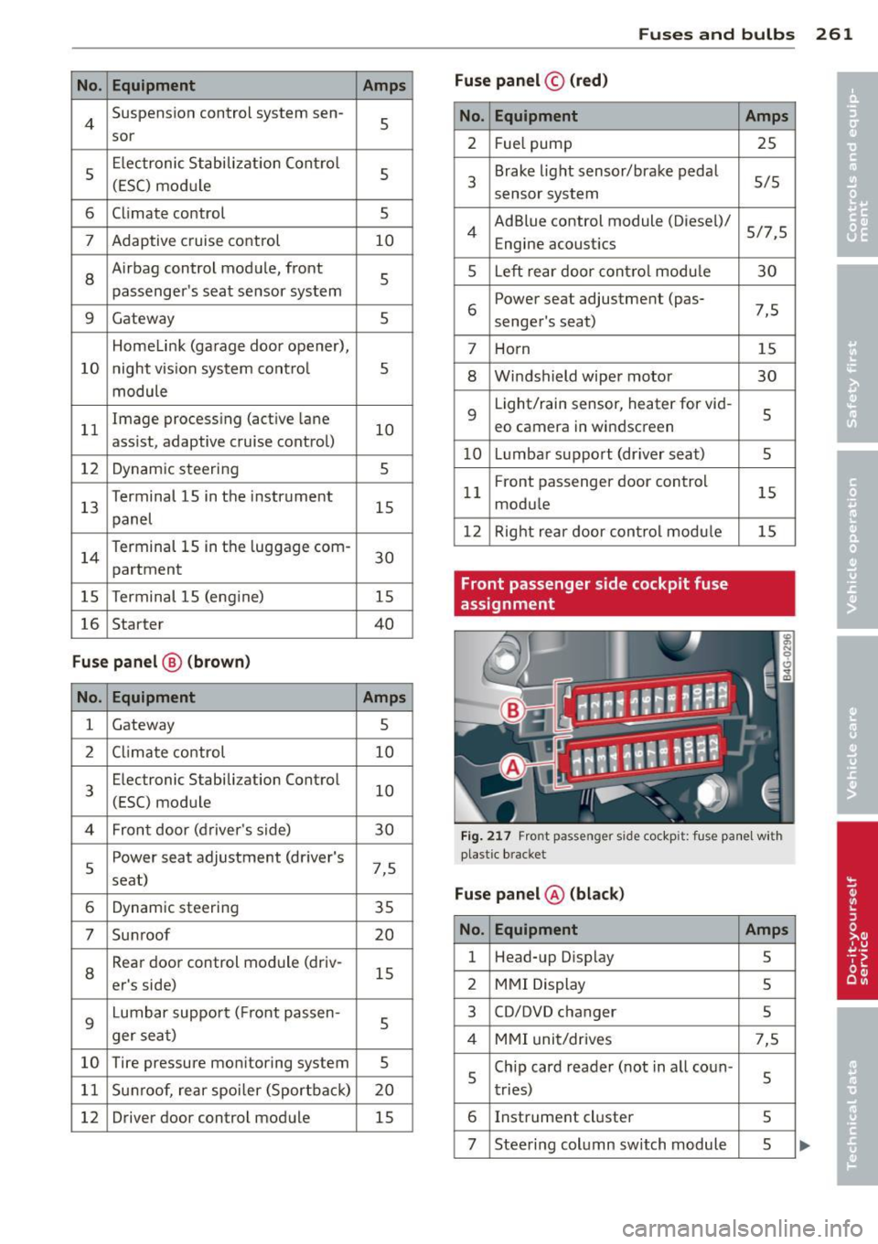
No. Equ ipment Amps
4 Suspension control system sen-s sor
s
E
lectronic Stabilization Cont rol
s (ESC) module
6 Climate control
5
7 Adaptive cruise control 10
8
Airbag control module, front
5
passenger's seat sensor system
9 Gateway 5
Homelink (garage doo r opener),
10 night vis ion system cont ro l 5
module
11 Image
processing (active lane
10
ass ist, adaptive cruise control)
12 Dynamic steering 5
13 Terminal 15 in
the instrument
15
panel
14 Terminal 15
in the luggage com-
partment 30
15 Terminal 15
(engine)
15
16 Starter 40
Fu se pa nel ® (b rown )
No . Equipment Amps
1 Gateway
5
2 C limate control 10
3 E
lectronic Stabili zation Contro l
10
(ESC) module
4 Fron
t door (driver 's side)
30
s
Power seat adjustment (driver's
7,5
seat)
6 Dynam
ic steering
35
7 Sunroof 20
8
Rear door control module (driv-
15
er 's side)
9 Lumbar support (
Front passen-
s ger seat)
10 Tire pressure
monitoring system
5
11 Su
nroof, rear spoi ler (Sportba ck)
20
12 Driver
door control module
15
Fuse s and bulb s 261
Fuse pan el© (r e d )
No . Equipment
2 Fuel pump
3 Brake light sensor/brake pedal
sensor system
AdBlue control module (Diesel)/
4 Engine acoust ics
5 Left rear door cont rol modu le
6 Power seat adjustment
(pas-
senge r's seat)
7 Horn
8 Windshield wiper motor
9 Light/rain sensor, heater
for vid-
eo camera in windscreen
10 L umba r support (driver seat)
1 1 Front
passenger door control
modu le
12 Right rea r door cont rol modu le
Front passenger side cockpit fuse
assignment Amp
s
25
5/5
5/7,S 30
7,5 15
30
s
5
15
15
F ig . 217 Front passenger side cockpit: fuse pa nel w it h
plast ic brac ket
Fuse panel @ (bla ck)
No . Equipment Amps
1 Head-up
Display
5
2 MMI Display 5
3 CO/DVD changer
5
4 MMI unit/drives 7,5
5 Chip
card reader (not in all coun-
5
tries)
6 Instrument
cluster
5
7 Steering column switch module 5 ...