service indicator AUDI S3 2009 Owners Manual
[x] Cancel search | Manufacturer: AUDI, Model Year: 2009, Model line: S3, Model: AUDI S3 2009Pages: 324, PDF Size: 76.02 MB
Page 10 of 324
Instruments and warning/indicator lights
Instruments and warning/indicator lights
Instruments
Instrument cluster and controls
The ins trum ent cluster is your central source of informa
ti on.
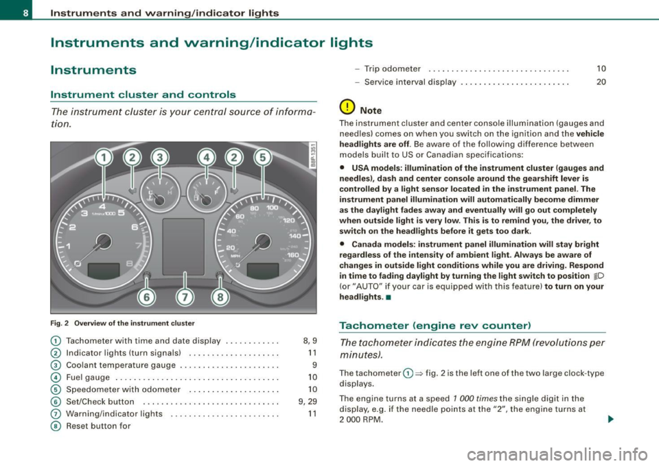
Fig . 2 Overv ie w of th e instrume nt clu ster
0
0
0
©
©
©
G)
©
T achometer with time and date display ......•.....
I ndicator lights (turn signals) ... ....... .... ..... .
Coo lant temperature gaug e .... ... ...... ...... .. .
Fuel gauge .. ... .... .. ...... .... ... ..... ... ... .
S pe edom eter wi th o do met er ..... .... ... .. .. ... .
Se t/Chec k button ..... ... ..... ..... ... ........ .
Warn ing/indicator l ights
Reset but ton for 8,9
1 1
9
1 0
1 0
9 , 29
1 1
- Trip odomete r 10
-Service i nterv al dis play . . . . . . . . . . . . . . . . . . . . . . . . 20
(D Note
The instrument clu ste r and center c onsole i lluminati on (gauge s and
n eedles) comes on w hen you sw itch on the ignit ion and the vehicle
he adl ights are off . Be awa re of the following difference betw een
models built to US or Canad ian specificat io ns:
• USA models : illumination of the instrument cluster (gauges and
needles), dash and center con sole around the gear shift lever is
controlled by a light sensor located in the instrument panel. The
instrument panel illumination will automatically become dimmer
as the daylight fades away and eventually will go out completely
when outside light is very low . This is to remind you, the driver , to
sw itch on the headlights befo re it gets too dark .
• Canada models: instrument panel illumination will stay bright
regardless of the intensit y of ambient light . Always be aware of
changes in outside light conditions while you are driving . Respond
in time to fading dayl ight by turning the light swit ch to position
jD
(or" AUTO" if you r car i s equi ppe d with this feature) to turn on your
headlights . •
Tachometer (engine rev counter)
T h e ta chom eter ind icates the e ngine RPM (revo luti ons pe r
minut es).
The tachom eter 0 => fig . 2 is the left on e of the two large clock -type
dis plays .
The engine turns at a speed 1 000
times the single di git in the
display, e.g . if the needle p oints at the "2", the eng ine t urns at
2 000 RP M.
Page 22 of 324
Driver informati on displ ay
Service Interval Display
The Service Interval Display is a reminder of the next
service due.
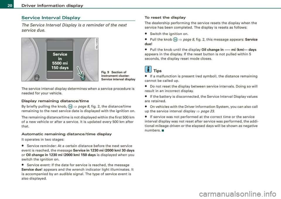
F ig . 9 Sect io n of
i n strum en t cl uster:
Se rv ice in terva l d isplay
The service interval display determines when a service procedure is
needed for your vehicle.
Di sp lay re main ing di sta nce/ tim e
By briefly pulling the knob,@~
page 8, fig. 2, the distance/time
remaining to the next service date is displayed with the ignition on.
The remaining distance/time is not displayed within the first 500 km of a new vehicle or after a service . It is updated every 500 km after
that.
A utom ati c re maini ng d ista nce/ tim e dis play
It operates in two stages:
• Service reminder: At a certa in distance before the next service
event is reached, the message
S ervice in 12 30 mi (2000 km ) 3 0 d ays
or Oil ch ange in 1 230 mi (2000 km ) 15 0 days is displayed when you
switch the ignition on.
• Service event : If the date for service is reached, the message
S ervic e due! appears and the wrench indicator light il luminates. It
is accompanied by an audib le signal. The type of service event is
a lso displayed. T
o r eset the disp lay
The dealership performing the service resets the display when the service has been completed. The display is resets as follows :
• Switch the ignition on .
• Pull the knob@)~
page 8, fig. 2, this message appears: S erv ice
du e!
• Pull the knob until the display Oil chang e in ----- mi (km )--- days
appears in the display . If the reset button is not pulled within 5
seconds, the disp lay reset mode c loses.
[ i ] Tip s
• If a malfunction is present (red symboll, the distance remaining
cannot be called up.
• Do not reset the display between service interva ls . Doing so will
resu lt in an incorrect display .
• If the battery is disconnected, the Service Interva l Display values
are retained.
• On vehicles with the Driver Information System, you can also call
up the service interval display~
page 23.
• If service was not performed at the correct time or the service
interva l display was not reset after service was performed, the addi
tional mileage driven or the elapsed days will be shown as negative
numbers. •
Page 23 of 324
On-Board Diagnostic system (08D)
On-Board Diagnostics
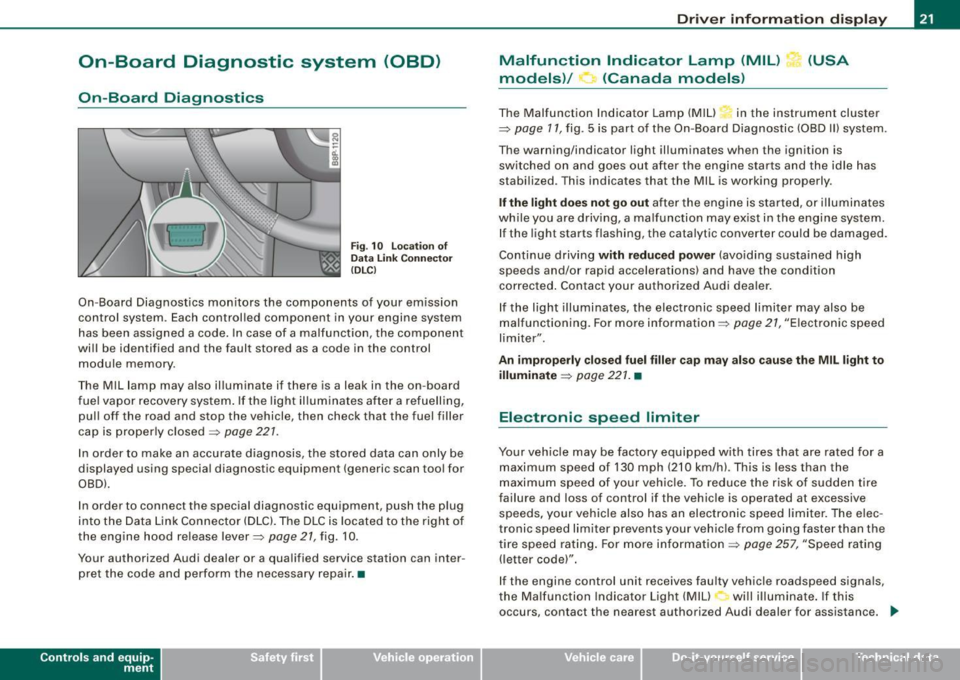
Fig. 10 location of
Data Link Connecto r
( DL C)
On-Board Diagnostics monitors the components of your emission
control system . Each controlled component in your engine system
has been assigned a code. In case of a malfunction , the component
will be identified and the fault stored as a code in the control
module memory .
The Mil lamp may also illuminate if there is a leak in the on-board
fuel vapor recovery system . If the light illuminates after a refuelling,
pull off the road and stop the vehicle, then check that the fuel filler
cap is properly closed=>
page 227.
In order to make an accurate diagnosis, the stored data can only be
displayed using special diagnostic equipment (generic scan tool for
OBDl.
In order to connect the special diagnostic equipment, push the plug
into the Data Link Connector (DLC). The DLC is located to the right of
the engine hood re lease lever=>
page 21, fig. 10 .
Your authorized Audi dealer or a qualified service station can inter
pret the code and perform the necessary repair. •
Contro ls and eq uip
ment
Driver information display
Malfunction Indicator Lamp (MIL) (USA
models)/ (Canada models)
The Malfunction Indicator Lamp (MIU in the instrument cluster
=> page 17, fig . 5 is part of the On-Board Diagnostic (OBD II) system .
The warning/indicator light illuminates when the ignition is
switched on and goes out after the engine starts and the idle has
stabilized. This indicates that the Mil is working properly .
If the light does not go out after the engine is started, or illuminates
while you are driving, a ma lfunction may exist in the engine system.
If the light starts flashing, the catalytic converter cou ld be damaged.
Continue driving
with reduced power (avoiding sustained high
speeds and/or rapid accelerations) and have the condition
corrected . Contact your authorized Audi dealer.
If the light illuminates , the electronic speed limiter may also be
malfunctioning. For more information=>
page 27, "Electronic speed
limiter".
An improperly closed fuel filler cap may also cause the MIL light to
illuminate => page 221. •
Electronic speed limiter
Your vehicle may be factory equipped with tires that are rated for a
maximum speed of 130 mph (210 km/h) . This is less than the
maximum speed of your vehicle. To reduce the risk of sudden tire
failure and loss of control if the vehicle is operated at excessive
speeds, yo ur vehicle also has an electronic speed limiter. The elec
tronic speed limiter prevents your vehicle from going faster than the
tire speed rating. For more information
=> page 257, "Speed rating
(letter code)".
If the engine control unit receives faulty vehicle roadspeed signals,
the Malfun cti on Indicator Light (MIU will illuminate . If this
occurs, contact the nearest authori zed Audi dealer for assistance. _.,
Vehicle care I I irechnical data
Page 33 of 324
-Turn off the engine.
- Check coolant level => page
233 .
-Add coolant if necessary => page 234 .
-Continue driving only after the engine coolant
warning/indicator light goes out.
- Contact your authorized Audi dealer for assistance if
necessary.
If the engine coolant level is correct, then the radiator fan may be
the cause of the malfunction.
If the generator warning/indicator light should also illuminate
=> page 14, then the fan belt may be damaged .
& WARNING
• If your vehicle should break down for mechanical or other
reasons, park at a safe distance from moving traffic, turn off the
engine and turn on the hazard warning lights
=> page 58, "Emer
gency flasher
A".
• Never open the hood if you see or hear steam or coolant
escaping from the engine compartment -you risk being scalded.
Wait until you can no longer see or hear steam or coolant
escaping.
• The engine compartment of any vehicle is a dangerous area.
Before you perform any work in the engine compartment, turn off
the engine and allow it to cool . Follow the warning stickers
=> page 217, "Engine compartment" .
0 Note
Do not continue driving if the -IL symbol illuminates. There is a
malfunction in the engine cooling system -you could damage your
engine. •
Controls and equip
ment
Driver information display
Engine oil pressure malfunction 'l=;:f.
The red engine oil pressure warning symbol requires
immediate service or repair.
If the 'l=::7-: symbol appears in the display and flashes, the oil
pressure is too low. In addition to the symbol, the following
message also appears in the display:
Switch off engine and check oil level
-Pull off the road and stop the vehicle.
Shut the engine down.
Check the engine oil level=> page
229.
Contact your authorized Audi dealer for assistance if
necessary.
Engine oil level too low
If the engine oil level is too low, top off oil to the proper level
=> page 230.
Engine oil level OK
If the ~ symbol star ts flashing again even though the engine oil
level checks OK on the dipstick,
do not start driving again and do not
let the engine run at idle .
Instead, contact your authorized Audi
dealer for assistance.
[ i] Tips
• The engine oil pressure symbol ~ is not an indicator for a low
engine oil level. Do not rely on it. Instead, check the oil level in your
engine at regular intervals, preferably each time you refuel, and
always before going on a long trip.
• The yellow oil level warning indication requires oil refill or
workshop service without delay. Do not wait until the red oil pres
sure warning symbol
~ starts to flash before you respond to the ...
I • •
Page 35 of 324
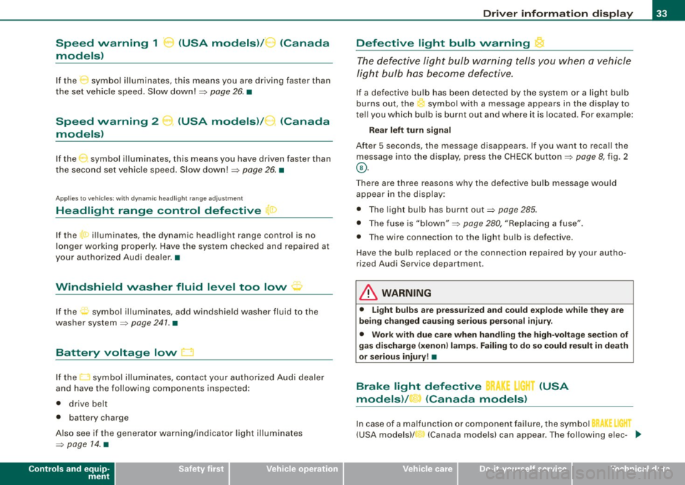
Speed warning 1 C (USA models) /'" (Canada
models)
If the symbol illuminates, this means you are driving faster than
the set vehicle speed. Slow down!=>
page 26. •
Speed warning 2
models) (
USA models) / (Canada
If the symbol illuminates, this means you have driven faster than
the second set vehicle speed. Slow down! =>
page 26. •
App lies to vehicles: w ith dynamic headlight range adjustment
Headlight range control defective ~ >
If the ·r illuminates, the dynamic headlight range control is no
longer working properly. Have the system checked and repaired at
your authorized Audi dealer. •
Windshield washer fluid level too low ' · '
If the rt symbol illuminates, add windshield washer fluid to the
washer system=>
page 241. •
Battery voltage low D
If the t::J symbol illuminates, contact your authorized Audi dealer
and have the following components inspected:
• drive belt
• battery charge
Also see if the generator warning/indicator light illuminates
=>
page 14. •
Controls and equip
ment
Driver information display
Defective light bulb warning ~
The defective light bulb warning tells you when a vehicle
light bulb has become defective.
If a defective bulb has been detected by the system or a light bulb
burns out, the ' symbol with a message appears in the display to
tell you which bulb is burnt out and where it is located. For example:
Rear left turn signal
After 5 seconds, the message disappears. If you want to recall the
message into the display, press the CHECK button=>
page 8, fig. 2
©-
There are three reasons why the defective bulb message would
appear in the display:
• The light bulb has burnt out=>
page 285.
• The fuse is "blown" => page 280, "Replacing a fuse" .
• Th e wire connection to the light bulb is defective.
Have the bulb replaced or the connection repaired by your autho
rized Audi Service department.
& WARNING
• Light bulbs are pressurized and could explode while they are
being changed causing serious personal injury.
• Work with due care when handling the high-voltage section of
gas discharge (xenon) lamps. Failing to do so could result in death
or serious injury! •
Brake light defective BR !.I" (USA
models) / (Canada models)
In case of a malfunction or component failure, the symbol
(USA models)/ (Canada models) can appear. The following elec- .,_
I • •
Page 165 of 324

& WARNING
Items stored between the safety belt buckle and the center
console can cause the sensors in the buckle to send the wrong
information to the electronic control module and prevent the
Advanced Airbag System from working properly.
• Always make sure that nothing can interfere with the safety
belt buckles and that they are not obstructed.
as Perchlorate Material -special handling may apply, see
www.dtsc.ca.gov/hazardouswaste/perchlorate. When the vehicle or
parts of the restraint system including airbag modules and safety
belts with pretensioners are scrapped, all applicable laws and regu
lations must be observed . Your authorized Audi dealer is familiar
with these requirements and we recommend that you have your
dealer perform this service for you. •
Safety first
Side airbags
Description of side airbags Airbag
system
The airbag
system can provide supplemental protection
to properly restrained occupants.
Fig . 147 Side airbag
location in the driver 's
seat
The side airbags are located in the sides of the front seat backrests
~ fig . 147 and the rear backrest * facing the doors. They are identi
fied by the word "AIRBAG" .
The side airbag system basically consists of:
• the electronic control module and external side impact sensors
• the two side airbags located in the sides of the front backrests
• two rear side airbags (as an ordered
option)
• the airbag warning light in the instrument cluster.
The airbag system is monitored electronically to make certain that
it is functioning properly at all times. Each time you turn on the igni
tion, the airbag system indicator light will come on for a few
seconds (self diagnostics) .
The side airbag system supplements the safety belts and can help
to reduce the risk of injury to the driver's , front and rear*
passenger's upper torso on the side of the vehicle that is struck in a
side collision . The airbag deploys only in side impacts and only
when the vehicle acceleration registered by the control unit is high
~
Vehicle care I I irechnical data
Page 256 of 324
___ T_ i_ r_e _s_ a_ n_ d_ w_ h_ e_ e _ ls _________________________________________________ _
Tire service life
The service life of tires depends on a Jot of different things
including proper installation and balancing, correct tire
pressure and driving style .
(r
l \._ _____ ;)
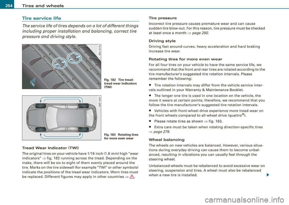
Tread Wear I nd ica tor ( TWll
Fig. 182 Tire tread:
tr ea d wea r ind ica tors
( TWIJ
Fi g. 1 83 Ro tati ng tir es
for mor e even wea r
The or iginal tires on your vehicle have 1/16 inch (1.6 mm) high "wear
indicators":::::, fig. 182 running across the tread . Depending on the
make, there will be six to eight of them evenly placed around the
tire . Marks on the tire sidewall (for example "TWI" or other symbols)
indicate the positions of the tread wear indicators . Worn tires must
be replaced. Dif ferent figures may apply in other countries:::::,&.
Tir e p re ss ure
Incorrect tire pressure causes premature wear and can cause
sudden tire blow-out . For this reason, tire pressure must be checked
at least once a month :::::,
page 250.
Drivin g sty le
Driving fast around curves, heavy acce leration and hard braking
increase tire wear .
Rotating tires for more even wear
For all four tires on your vehicle to have the same service life, we
recommend that the front and rear tires are rotated according to the
tire manufacturer's suggested tire rotation intervals . Please
r emember the following:
• Tire rotation interva ls may differ from the vehic le service inter
vals outlined in your Warranty
& Maintenance Booklet.
• The longer one tire is used in one location on the vehicle, the
more it wears at certain points; therefore, we recommend that you
follow the tire manufacturer's suggested tire rotation intervals.
• Vehicles with front -wheel drive experience mo re tread wear on
the front wheels compared to all-wheel drive (quattro®) .
• Please rotate tires as shown :::::, fig . 183.
• Extra care must be taken when rotating direction -specific tires
:::::, page 279.
Whe el b ala n cing
The wheels on new vehicles are balanced. However, various situa
tions during everyday driving can cause them to become unba l
anced, resulting in vibrations you can usual ly feel through the
steering wheel.
Unba lanced whee ls must be rebalanced to avoid excessive wear on
steering, suspension and tires. A wheel must a lso be reba lanced
when a new tire is installed.
~
Page 260 of 324
-~_T_ ir_e_ s_ a_ n_d _ w_ h_ e_e _l_s _________________________________________________ _
toring system* would not be able to monitor the tire pressure or
warn yo u if it is n ece ssa ry .
• The battery inside of t he ti re pressure sensor has a l imited
service life.
• Always driv e with the valv e stem caps s ecurely mount ed. We
r ecomme nd u sing fact ory insta lled valve s tem caps . As k your autho
rized Audi d ealer to replace lost va lve stem caps.
T he installation of rep lacement tires with steel cord body p lies in
the t ir e si dewa ll may caus e malf unc tio n of th e tir e pre ssure mo ni
toring system*, and is not recommended (cord material informat ion
in mo lded o n th e tire s idewa ll).
Always check your tire pressu re monitoring system* indicator after
r eplacing one o r more tir e s on yo ur veh icle . If the ti re p ressure
monito ring sy ste m* in dicato r flas hes or is illum inated, you r syste m
is not working p ro perl y. Yo ur replacement ti re might be incompat
i b le with you r tire p ressu re mo nitoring sys tem*, or some compo
nent of the tire pressure monitori ng system* may be damaged.
& WARNING
• Using incorrect or unmatched tires and I or wheels or improper
tire and wheel combinations can lead to loss of control , collision
and serious personal injury .
• Always use tires , rims and wheel bolts that meet the specifica
tions of original factory-installed tires or other combinations that
have been specifically approved by the vehicle manufacturer.
• Tires age even if they are not being used and can fail suddenly,
especially at high speeds . Tires that are more than 6 years old can
only be used in an emergency and then with special care and at
lower speeds .
• Never mount used tires on your vehicle if you are not sure of
their "previous history ." Old used tires may have been damaged
even though the damage cannot be seen that can lead to sudden
tire failure and loss of vehicle control.
& WARNING (continued)
• All four wheels must be fitted with radial tires of the same type,
size (rolling circumference ) and the same tread pattern. Driving
with different tires reduces vehicle handling and can lead to a loss
of control.
• If the spare tire is not the same as the tires that are mounted
on the vehicle - for e xample with winter tires - only use the spare
tire for a short period of time and drive with extra care . Refit the
normal road wheel as soon as safely possible.
• Never drive faster than the maximum speed for which the tires
on your vehicle are rated because tires that are driven faster than
their rated speed can fail suddenly .
• Overloading tires cause heat build-up , sudden tire failure ,
including a blowout and sudden deflation and loss of control .
• Temperature grades apply to tires that are properly inflated and
not over or underinflated .
• For te chnical reasons it is not always possible to use wheels
from other vehicles -in some cases not even wheels from the
same vehicle model.
• If you install wheel trim discs on the vehicle wheels, make sure
that the air flow to the brakes is not blocked. Redu ced airflow to
the brakes can them to overheat , increasing stopping distances
and causing a collision.
• Run flat tires may only be used on vehicles that were equipped
with them at the fa ctory . The vehicle must have a chassis designed
for run flat tires and a factory-installed tire pressure monitoring
system * that indicates a loss of tire pressure . Incorre ct use of run
flat tires can lead to vehicle damage or accidents . Check with an
authorized Audi dealer or t ire specialist to see if your vehicle can
be equipped with run flat tires .
If run flat tires are used, they must
be installed on all four wheels . Mixing tire types is not permitted. .,
Page 313 of 324

Alphab eti ca l ind ex -
-------------=----
Convenience close/open feature
Windows . .... .... .... ... ... ..... . 47
Convertible child safety seats
How do I properly install a convertible
ch ild seat in my vehicle? . ...... .. 175
Safety instructions .. ... .... ... .. . 175
Convertible locking retrac tor
Activating ... ... ... .. ... ... .. .... 181
Deactivating .. .... .... ... ... ..... 182
Using to secure a child safety seat 179, 181
Coolant system . .... .... .... .... ... . 232
Cooling System Expansion tank ... ................ 233
Cornering light .... .... .... .... .... .. 55
Cruise contro l ...................... 113
Changing speed .................. 114
Presetting your speed ... .... .... .. 114
Swi tching off .. ...... .... ... .... . 114
Swi tch ing on .. ...... .... ....... . 113
Warning/indicator lights . ... .. .... .. 14
Cup holder .......................... 92
Cup holders front ......... ...... ...... ..... .. 91
Current fuel mileage .... .... ... .. .. .. . 22
D
Damping
See Audi magnetic ride .. .... .. .... 115
Data .. .... ... ... .. .... .... ... .... . 300
Data recorder ....................... 190
Date display ... .. ... ... .... ... .... .... 9
Controls and equip
ment Safety first
Daytime running lights
.. ... .... .... .. . 54 Driver information system
Daytime running lights (Canada) .. .. ... . 55 Gearshift indicator
..... .. .... .... .. 19
Dec laration of compliance Menu button ..
........ .... ...... .. 25
Ce ll phone package ............... 307 Open door or front lid warning .
.... . 18
Electronic immobilizer ............ 307 Outside temperature display
.... .... 18
Home link® universal remote control 307 Red symbols
...... .... .. . .. .. .... . 28
Remote control key ...... .. .. .... . 307 Setting
... .... .... .... ... .... ..... 26
Tire pressure monit oring system . ... 307 Sound system disp
lay ........ ... .. . 18
Dec laration of conform ity ... .... .... . 268 Trip compu
ter ... .. .... ... .... .... . 22
def yellow symbols .
...... .... .... ..... 29
What does this mean when it appears in Dr
iver seat
t he trip odometer d isplay? .. ...... . 10
See Seating position ... ... .... .... 128
Defective light bulb warning . .......... 33 Driving safely
....................... 126
Defogg ing the windows ... .. .... .... . 10 1 Dup
lica te key . ...... .... ... .... .... .. 35
D efrosting the windows .. ... ..... ... . 101
Defrosting/defogging windows .... .... 104
E
Determining correct load limit . ...... . 252
Elapsed time .. ...... .... ... .... .... . 22
Digita l clock ..... .. .... .... .... ...... . 9
Setting the time ............. ... .. .. 9
Digita l compass . .... ... .... .... .... .. 72 Electrically heated front seats
......... 105
Electro -mechanical power assist . ... 16, 195
Electronic differential lock
Dimensions . ..... ... .... .... .... ... 299
Warning/indica tor lights .... .... .... 16
Dipstick Electronic differential lock (EDU
Reading the dipstick properly ..... . 229
How the system works .... .... .... 191
Direct Shift Gearbox
Emergency release ... .... .... .... 1 23
Distance . .... ... ...... ...... .... .... 23 Elect
ronic immobilizer . ...... .... .. 10, 37
Electro nic power contr ol
EPC warning/indicator light ... .... .. 13
Doors, power locks .. ... .... ..... ... .. 40
Electronic speed limiter ............... 21
Driver information ...... .. .... .... ... . 29
Driver Information System
Menu display . ...... .. .... ..... .. . 23 Electronic Stability Program
...... ... . 190
Electron ic stabil ization program (ESP)
Warning/ind icator lights .... .... .... 13
Emergency flasher Warning/indicator lights .... ...... .. 14
Vehicle operation Vehicle care Do-it-yourself service Technical data
Page 315 of 324

Alphabetical index -
-------------=----
Saving fuel by upshifting early ... .. 8, 9
Using the rear window defogger .... 105
Front airbags
Description ... ....... .... .. . .... . 151
How th ey work . . . . . . . . . . . . . . . . . . . 156
Front seats ......... .... ... .... ...... 74
Adjusting ................... .... 129
Adjusting the manual seats .. .. .... . 76
Child restraints in the front seat .. .. 149
Heated seats . . . . . . . . . . . . . . . . . . . . . 105
Fronta l collisions and the laws of physics
138
Fuel Current fuel mileage ........... .... 22
Fuel gauge ...... .... .... ...... ... 10
Fuel supply too low ...... .... .... .. 32
Fuel filler f lap
Unlocking the fuel filler flap by hand 223
Fuel gaug e .... .... ...... .. .... ..... . 10
Fuel range .. .... .... .... .... ... .... . 22
Fuel supply Additives . .... .... .... ... ..... ... 219
Blended gasoline ... .. ........ .... 219
Fuel filler neck ... .... .... ........ 220
Fuel gauge ...... .... .... ........ . 10
Fuel tank capacity ........... .. 10, 220
Gasoline ... .. .... .... ........... 219
Gasoline additives . ... .... ....... . 220
Octane rating . .... .... ... .... .... 219
Recommendation . .. .. .. .... .... . 219
Refu elling .... ..... ... ..... .. ... . 221
Unlocking the fuel filler flap by hand 223
Controls and equip ment Safety first Fuel
tank
Capacity . .... ...... ........ ..... 220
Capacity (gal lons/liters) ...... ... .. .. 10
Fuse arrangemen t ... .. .. .... ... .... . 281
G
Gas discharge lamps .. .. ..... .. .... . 285
Gauges Engine coolant temperature .. ..... ... 9
Fuel gauge ... .. .... .... .. .. .... .. 10
Speedometer ... ...... .... .... .... 10
Tachometer .......... .... ... .... .. 8
Trip odometer . ................... 10
Gear recommendation ..... ...... .... . 19
Gearshift indicator .. ...... .... .... ... 19
Gearshift lever ........ ... .... ....... 116
Genera l illustration
Instruments and controls . .... .... ... 7
Generator Warning /indicato r lights .. .. .... .... 14
Glossary of tire and loading terminology .. .
244
G love compartment ... .. .... ... .... .. 95
Light .... ... ... .. .... .... ........ 60
Gross Vehicle Weight Rating (GVWR) ... 299
H
Head restraints ........ ...... ... .... 131
Adjusting ... ... ................. 131
Rear seats ... ... .. ........ ........ 80 Headlight
defective . .... .... .... ...... ... .. . 33
Head light range control
defective ..... .... .... .. . ......... 33
Headlights ... ... ...... ..... .. ...... . 52
adaptive light ..... .... ....... ..... 55
Front fog lights . ..... .. ............ 56
Switching off . ... .... .... .... .. .. . 52
Switching on ...... .... .. .. .... .... 52
Washer system .. ...... ... .... .. . .. 66
Heated rear window ..................... 105
Heated outside mirrors ... .... ... ... ... 70
Heated washer jets
Wiper and washer system ........... 63
Heavy clothing and safety be lts .... .... 140
High beam ... .... ..... .. .... ..... 5 2, 59
Warning/indicator lights .. .... .... .. 14
High vo ltage warning label . ...... .... 298
Hi ll Descent Assist .... ... .... .... .... 120
Hill hold assist Starting on hills ... ... ... .... .... . 111
hood
See Engine hood ..... .... .... .... 224
Hood re lease .... ..... .. .... .... .... 224
Horn ... .... .... .... ... .... .... ..... . 7
How many airbags does my vehicle have? ..
154
How often shou ld I check my tire pressures?
251
How safety belt pretensioners work .. .. 145
Hydroplaning ...... .. ...... .... .... . 255
Vehicle operation Vehicle care Do-it-yourself service Technical data