AUDI S3 2010 Owners Manual
Manufacturer: AUDI, Model Year: 2010, Model line: S3, Model: AUDI S3 2010Pages: 320, PDF Size: 75.34 MB
Page 291 of 320

________________________________________________ E_ m_ e_r ,,::g c..e_ n _ c..::y;._ s_ i_t _u _a_ t_ i_o _n_ s _ ___.ffllll
& WARNING
A vehicle being towed is not safe for passengers. Never allow
anyone to ride in a vehicle being towed, for any reason. •
Front towing loop
Do not install the front towing loop until it is needed.
Fig. 197 Front
bumper : removing the
cover cap
Fig . 198 Front
bumper : screwing in
the towing loop
The towing loop fits into the threaded hole located on the
right side of the front bumper and covered by a small cover
when not in use. Note that the towing loop has a
left-hand
thread !
-Remove the towing loop from the vehicle toolkit
=:>
page 268.
- Press on the bottom edge of the cover cap to disengage
and take it out of the bumper. The cap remains
connected to the bumper =:> fig. 197.
- Insert the towing loop into the threaded hole=:> fig. 198
and turn it all the way in until it is seated securely, then
tighten it with the wheel bolt wrench.
When it is no longer needed, unscrew the towing loop and put it
back into the on-board toolkit. Make sure to have the towing loop
stored in the vehicle at all times.
& WARNING
If the towing loop is not screwed in as far as it will go, the thread
can pull out when the vehicle is towed -potential risk of an
accident. •
Rear towing loop
Do not install the rear towing loop until it is needed.
Fig. 199 Rear bumper:
cover ....
Vehicle care Do-it-yourself service irechnical data
Page 292 of 320

IIII...__E_ m_ e_ r -'g==-- e_n _ c_ y=--- s_ i_ t _u _a _ t_ i_o _n _ s _____________________________________________ _
Fig. 200 Rear bumper:
towing loop inserted
On the right side of the rear bumper there is a threaded hole
for the towing loop. The threaded hole is behind a cover.
Note that the towing loop has a left-hand thread!
Remove the towing loop from the vehicle toolkit
~ page 268.
Place the screwdriver against the upper edge of the
cover and carefully pry it out~
page 289, fig. 199.
- Insert the towing loop into the threaded hole~ fig. 200
and turn it all the way in until it is seated securely, then
tighten it with the wheel bolt wrench.
When it is no longer needed, unscrew the towing loop and put it
back into the vehicle toolkit. Be sure to have the towing loop stored in the vehicle at all times.
& WARNING
If you do not screw the towing loop completely, it could come out
of the threaded hole while the vehicle is being towed causing
damage to the vehicle and possible serious personal injury. •
Loading the vehicle onto a flat bed truck
Front
hook up
N
"' :? 0:. .,
"'
Fig. 201 Vehicle on flat
bed truck
-Align the vehicle with the centerline of the car carrier
ramp.
- Attach the winch hook to the front towline eye
~ page 289, fig. 198 previously installed.
Rear hook up
-Align the vehicle with the centerline of the car carrier
ramp.
- Attach the winch hook to the rear towline eye~ fig. 200
previously installed.
[ i] Tips
Check carefully to make sure the hook -up is secure before moving
the car up the flatbed truck ramp. •
Page 293 of 320

________________________________________________ E_ m_ e_r .::g :...e_ n _ c_,y'-- s_ i_t _u _a_ t_ i_o _n_ s _---J_
Lifting the vehicle
Important safety precautions
Be aware of the following hazards before lifting the vehicle with a
workshop hoist or floor jack:
• The vehicle should never be lifted or jacked up from underneath
the engine oil pan, the transmission housing, the front or rear axle
or the body side members. This could lead to serious damage.
• Use lifting equipment with padded contact surfaces to avoid
damage to the underbody or chassis frame.
• Alternatively, cover the contact surfaces on workshop hoist or
floor jack with rubber pads before lifting .
• Before driving over a workshop hoist, check that the vehicle
weight does not exceed the permissible lifting capacity of the hoist .
• Before driving over a workshop hoist, ensure that there is suffi
cient clearance between the hoist and low parts of the vehicle .
& WARNING
To reduce the risk of serious injury and vehicle damage:
• Always lift the vehicle only at the special workshop hoist and
floor jack lift points illustrated
=> fig. 202 and => fig. 203 .
• Failure to lift the vehicle at these points could cause the vehicle
to tilt or fall from a lift if there is a change in vehicle weight distri
bution and balance. This might happen, for example, when heavy
components such as the engine block or transmission are
removed .
• When removing such heavy components, anchor vehicle to
hoist or add corresponding weights to maintain the center of
gravity . Otherwise , the vehicle might tilt or slip off the hoist,
causing serious personal injury. •
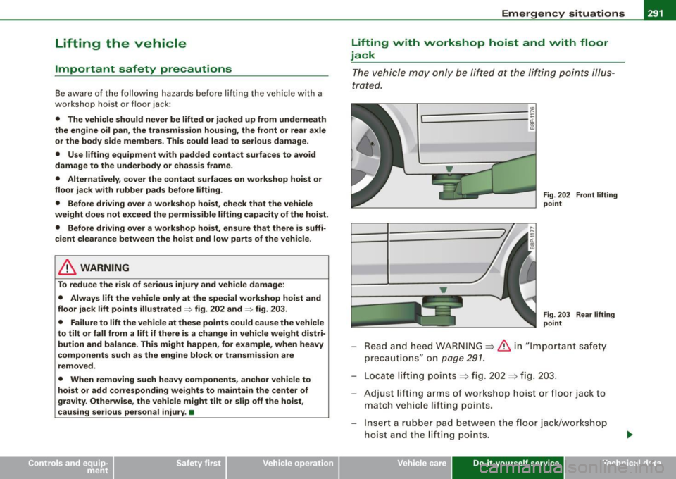
Lifting with workshop hoist and with floor
jack
The vehicle may only be lifted at the lifting points illus
trated.
.... L===========::::==:: ~ 0:.
Fig . 202 Front lifting
point
Fig . 203 Rear lifting
point
Read and heed WARNING ~ & in "Important safety
precautions " on
page 291.
Locate lifting points~ fig. 202 ~ fig. 203.
Adjust lift ing arms of workshop hoist or floor jack to
match vehicle lifting points.
Inse rt a rubber pad between the floo r jack/workshop
hoist and the lifting poin ts.
Vehicle care Do-it-yourself service irechnical data
Page 294 of 320

lllffl.___E_ m _ e _r-==g :...e_ n_ c...:y _ s_ i_t _u _a _t_ i_o _n_ s _______________________________________________ _
If you mu st lift your veh icle with a floor jack to work underneath , be
sure the vehicle is safely supported on stands intended for this
purpose .
Front lifting point
T he lifting point is located on the floor pan reinforcement about at
t he same leve l as t he jac k mou nti ng poi nt=>
pag e 291, fig. 202 . Do
not lift the vehicle at the vertical sill reinforcement .
Rear lifting point
T he lifting point is located on the vertical reinforcement of the lower
sill for the o n board jack=>
page 291, fi g. 203 .
Lifting with vehicle jack
Refe r to=> page 274.
0 Note
• Be aware of the fo llo wi ng po ints before l ifting t he ve hicle :
- The vehicle should never be lifted or jacked up from under
neath the engine oil pan , the transmission housing , the front or
rear axle or the body side members . This could lead to serious
damage.
- To avoid damage to the underbody or chassis frame , a rubber
pad must be inserted between the floor jack and the lift points .
- Before driving over a workshop hoist, check that the vehi cle
weight does not exceed the permissible lifting capacity of the
hoist .
- Before driving over a workshop hoist , ensure that there is
sufficient clearance between the hoist and low parts of the
vehicle. •
Page 295 of 320

________________________________________________ E _m_ e_r.:g :;,. e_ n_c ...: y:.- s_ i_ t _u _a_ t_ i_ o _ n_ s __ ffllll
• Do-it -yourself service
Page 296 of 320

___ G_ e_ n_ e_r_ a _ l_ in_ f_ o _r_m _ a_ t_ i_ o _ n __________________________________________________ _
General information
Explanation of technical data
Some of the technical data listed in this manual requires
further explanation.
The technical data for your vehicle is listed in the charts starting on
~ page 296. This section provides general information, notes and
restrictions which apply to this data. •
Vehicle identification
The key data are given on the vehicle identification
number (VIN) plate and the vehicle data sticker.
Fig. 204 Vehicle Identi
fication Number (VIN)
plate: location on
driver's side dash
panel Fig
. 205 The vehicle
identification label -
inside the luggage
compartment
The Vehicle Identification Number (VIN)
is located on the driver's side so that it is visible from the outside
through the windshield -see ~ fig. 204.
The vehicle identification label
is located in the luggage compartment in the spare wheel well.
The label ~ fig. 205 shows the following vehicle data:
© Production control no.
0 Vehicle identification no.
© Type code number
© Type designation/engine output in Kilowatts
© Engine and transmission code letter
© Paint no./lnterior
0 Optional equipment no.'s
Vehicle data 2 to 7 are also found in your Warranty
& Maintenance
booklet .
The safety compliance sticker
is your assurance that your new vehicle complies with all applicable
Federal Motor Vehicle Safety Standards which were in effect at the
time the vehicle was manufactured. You can find this sticker on the ._
Page 297 of 320

_________________________________________________ G_ e_ n_ e_r _a _l_ i_n _f_o _ r_ m_ a_ t _i _o _ n __ _
left door jamb. It shows the month and year of production and the
vehicle identification number of your vehicle (perforation) as well as
the Gross Vehicle Weight Rating (GVWR) and the Gross Axle Weight
Rating (GAWR).
The high voltage warning label
is located on the lock carrier.
The spark ignition system complies with the Canadian
standard ICES-002. •
Weights
Gross Vehicle Weight Rating
The Gross Vehicle Weight Rating (GVWR), and the Gross Axle Weight
Rating (GAWR) for front and rear are listed on a sticker on the left
door jamb.
The Gross Vehicle Weight Rating includes the weight of the basic
vehicle plus full fuel tank, oil and coolant, plus maximum load,
which includes passenger weight (150 lbs/68 kg per designated
seating position) and luggage weight.
Gross Axle Weight Rating
The Gross Axle Weight Rating is the maximum load that can be
applied at each axle of the vehicle ~& .
Vehicle capacity weight
The vehicle capacity weight (max. load) is listed either on the
driver's side B-pillar or inside the fuel filler flap .
Roof weight
The maximum permissible roof weight is 165 lb (75 kgl. The roof
weight is made up of the weight of the roof rack system and the
weight of the object being transported~
page 89, "Loading the
roof rack".
Controls and equip ment Safety first Vehicle operation
& WARNING
•
The actual Gross Axle Weight Rating at the front and rear axles
should not exceed the permissible weights, and their combination
must not exceed the Gross Vehicle Weight Rating.
• Exceeding permissible weight ratings can result in vehicle
damage, accidents and personal injury.
0 Note
• The vehicle capacity weight figures apply when the load is
distributed evenly in the vehicle (passengers and luggage). When
transporting a heavy load in the luggage compartment, carry the
load as near to the rear axle as possible so that the vehicle's
handling is not impaired.
• Do not exceed the maximum permissible axle loads or the
maximum gross vehicle weight. Always remember that the vehicle's
handling will be affected by the extra load. Therefore, adjust your
speed accordingly.
• Always observe local regulations.•
Dimensions
The specifications refer to the basic model. Differences may occur
depending on the model type and options ordered, for example, tire
sizes.
0 Note
When driving up steep ramps, on rough roads, over curbs, etc. it is
important to remember that some parts of your vehicle, such as
spoilers or exhaust system components, may be close to the
ground. Be careful not to damage them. •
Vehicle care Do-it-yourself service Tec hn ica l da ta
Page 298 of 320

___ D_ a_ ta ______________________________________________________ _
Data
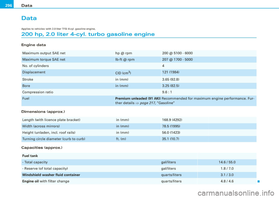
Applies to vehi cles: with 2.0 lite r TFS I 4-cyl. g asoline eng ine ,
200 hp, 2.0 liter 4-cyl. turbo gasoline engine
Engin e data
Maximum output SAE net
Maximum torque SAE net
No. of cy linders
Disp lacement
Stroke
Bore
Compression ratio
Fuel
D im ensio ns (a pprox.)
Length (with licence plate bracket)
Width (across mirrors)
Height (unladen, incl. roof rails)
Turning circle diameter (curb to cu rb)
Ca pacitie s (a pprox.)
F u el t ank
-Total capacity
- Reserve (of total capacity)
W ind shi eld was her fluid cont ain er
Engine oil
with filter change hp@rpm
lb
-ft@ rpm
CID (cm
3 )
in (mm)
in (mm)
200@ 5100 -6000
207 @ 1700 -5000
4 121 (1984)
3.65 (92.8)
3 .25 (82 .5)
9 .6 : 1
Premium unleaded (91 AKI) Recommended for maximum engine performance . Fur
ther det ails =:>
page 277, "Gasol ine"
in (mm)
in (mm)
in (mm)
ft. (ml
168.9 (4292)
78 .5 (1995)
56.0 (1423)
35.1 (10.7)
gal/liters
gal/liters
quarts/liters
quarts/liters 14 .6 / 55.0
1 .8/7.0
3 .1 / 3 .0
4 .8 / 4.6
•
Page 299 of 320

___________________________________________________ D_a_ t_ a __ !II
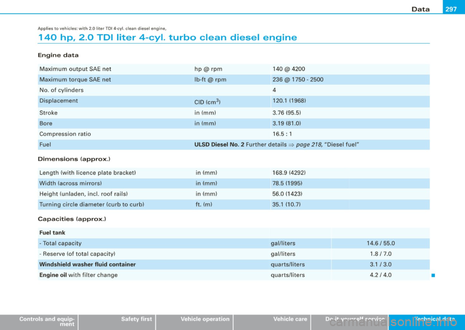
A pp lies to veh ic les : w it h 2 .0 liter TDI 4 -cyl. c le an di esel e ngin e,
140 hp , 2 .0 TOI liter 4-cyl. turbo clean diesel engine
Engine data
Maximum output SAE net
Maximum torque SAE net
N o. o f cy linders
Displacement
Stroke
Bore
Co mpression ratio
Fuel
Dimensions (approx .)
Length (with licence p late bracket)
Width (across mirrors) H eight (unla den, incl. roof ra ils)
Turning circle diameter (curb to curb)
Capacities (approx .)
Fuel tank
-Total capacity
- Reserve (of t otal capacity)
Wind shield wa sher fluid container
Engine oil
with filter change
Controls and equip ment Safety first
hp@rpm
lb-ft@ rpm
CID (cm
3
)
in (mm)
in (mm)
14 0 @4200
236 @ 1750 · 2500
4
120.1 (1968)
3 .76 (95 .5)
3.19 (81 .0)
16. 5: 1
ULSD Diesel No . 2 Further details=> page 218, "Diesel fue l"
in (mm)
in (mm)
in ( mm)
ft. (ml
Vehicle operation
168.9 (4292)
78.5 (1995) 56.0 (14 23)
35.1 (10.7)
gal/liters
gal/li te rs
quarts/liters
quarts/liters
Vehicle care
14.6 / 55.0 1.8/7.0
3.1 / 3_0
4.2 I 4 .0
Do-it-yourself service
•
T ec hn ica l da ta
Page 300 of 320

___ C_ o_n_ s_ u_m _ e_ r_ ln_ f_ o _r _m _ a_ t_ i_o _n ______________________________________________ _
Consumer Information
Warranty coverages
Your A udi i s cov ered b y the follo wing war ra nt ies:
• New Vehicle Limited Warranty
• Limited Warranty Against Corrosion Perforation
• Emissions Control System Warranty
• Emissions Performance Warranty
• California Emissions Control Warranty (USA vehicles only)
• California Emissions Performance Warranty (USA vehicles only)
Detailed information rega rding your warranties can be found in
your
W arr ant y & Maint ena nce Booklet .•
Operating your vehicle outside the
U .S.A. or Canada
Government regulations in the United States and Canada require
that automobiles meet specific em ission regulations and safety
standards. Therefore, vehic les bui lt for the U.S .A. and Canada differ
from vehicles sold in other countries .
If you plan to take your vehic le outside the continental limits of the
United States or Canada, there is the possibility that
• unleaded fue ls for vehicles with catalyt ic converter may not be
available;
• f uel may have a considerably lower octane rating . Improper fuel
may cause engine damage;
• service may be inadequate due to lack of proper service facilities,
tools or testing equipment;
• replacement parts may not be readi ly available . •
Navigation systems for vehicles built for the U.S.A . and Canada
wil l not necessarily work in Europe, and may not work in other coun
tries outside of North Amer ica.
Audi c annot be responsib le for me ch an ical damage that could
result from inadequate fuel , serv ice or parts availability .
0 Note
Audi cannot be responsible fo r mechanica l damage that could
result from inadequate fuel, service or parts avai lability .•
Audi Service Repair Manuals and
Literature
Audi Official Factory Service Manuals are published as soon as
possible af ter model introduction . Service manua ls are available
from:
Audi Te ch n ic al Liter ature Ordering Center
Ca ll toll -free:
Tel. :
1 (800) 544-802 1
(from 8:00 AM to 8:00 PM, EST, Mon day t hrough Friday)
or access their website
www .audi .dd sltd .com on the Internet to
order repair manuals and other Audi literature .•