instrument cluster AUDI S3 SEDAN 2015 Owners Manual
[x] Cancel search | Manufacturer: AUDI, Model Year: 2015, Model line: S3 SEDAN, Model: AUDI S3 SEDAN 2015Pages: 282, PDF Size: 71.14 MB
Page 12 of 282
Instruments and indicato r Lights
Instruments and indicator Lights
Instruments
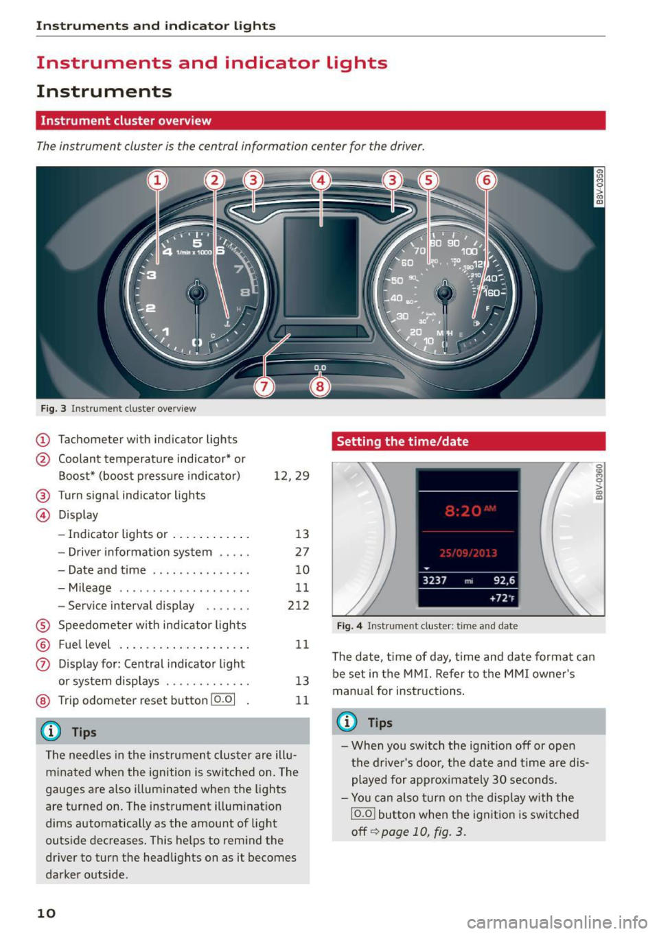
Instrument cluster overview
The instrument cluster is the central information center for the driver.
Fig. 3 Instrument cluster overview
(D Tachometer with indicator lights
@ Coolant temperature ind icator* or
Boost* (boost press ure indicato r)
® Turn signa l indicator lights
@ Display 12,29
- Indicator lights or . . . . . . . . . . . . 13
- Drive r information system . . . . . 27
- Date and time . . . . . . . . . . . . . . . 10
- Mileage . . . . . . . . . . . . . . . . . . . . 11
- Service interval display . . . . . . . 212
® Speedometer w ith indicator lights
® Fu el level .. ................ . .
0 Display for: Central indicator light
or system displays ..... ..... .. .
@ Trip odometer reset button 10.01
(D Tips
11
13
11
The needles in the instrument cluster are illu
minated when the ignition is switched on. The
gauges are also illuminated when the lights
are turned on . The instrument illum inat ion
dims automatically as the amount of light
outside decreases. This helps to remind the
driver to turn the headlights on as it becomes
darker outside.
10
Setting the time/date
Fig. 4 Instrument cluste r: time and date
The date, time of day, time and date format can
be set in the MMI. Refer to the MMI owner's
manua l for instructions .
(0 Tips
-When you switch the ignition off or open
the driver's door, the date and time are dis
played for approximately 30 seconds.
- You can also turn on the display with the
IO.O ! button when the ignition is switched
off
I:=;) page 10, fig. 3.
g .., 0 :> CX) m
Page 13 of 282
M N
0 > co ,...., \!) 1.1'1
1.1'1
1.1'1
,....,
Tachometer
The tachometer shows the number of engine rev
olutions per minutes .
The beginning of the red zone in the tachometer
indicates the maximum permissible engine speed
for all gears once the engine has been broken in
and when it is warm. You should select the "0/
S" (Drive) selector leve r position or take your foot
off the accelerator pedal before reach ing th is
area.
It is best to avoid high engine speeds, even when
driving in tiptronic mode
<=> page 87.
(D Note
The tachometer needle © c::> page 10, fig. 3
should only be in the red zone briefly:
@ For the sake of the environment
Upshifting early helps you to save fuel and re
duce operating noise .
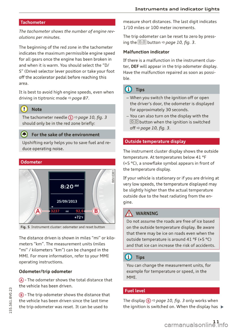
Odometer
Fig. S Instrument cluster : odo meter and reset button
The distance driven is shown in miles "mi" or kilo
meters "km". The measuremen t units (miles
"mi"
I kilometers "km") can be changed in the
MMI. For more information, refer to your MMI
operat ing instructions .
Odometer/trip odometer
@-The odometer shows the total distance that
the vehicle has been driven .
@-The trip odometer shows the distance that
the vehicle has been driven since the last time
the trip odometer was reset. It can be used to
Instruments and indicator lights
measure short distances. The last digit indicates
1/10 mi les or 100 meter increments.
T he trip odometer can be reset to zero by press
ing the
10.01 button <=> page 10, fig . 3.
Malfunction indicator
If there is a malfunct ion in the instrument clus
ter,
DEF will appear in the tr ip odometer display .
Have the malfunction repaired as soon as poss i
ble.
@ Tips
- When you switch the ign ition off or open
the driver's door, the odometer is disp layed
for approximately 30 seconds.
- You can also turn on the display with the
!O .O I button when the ignition is switched
off c::>
page 10, fig. 3.
Outside temperature display
The instrument cluster display shows the outside
temperature . At temperatures below 41 °F
(+ S °C), a snowflake symbol appears in front of
the temperature display .
If your vehicle is stationary or if you are driving at
very low speeds, the temperature displayed may
be slightly higher than the actual temperature
outside due to the heat radiating from the en
gine.
A WARNING
-Do not assume the roads are free of ice based
on the outside temperature display. Be aware
that there may be ice on roads even when the
outside temperature is around 41 °F (+5 °()
and that ice can increase the risk of accidents.
@ Tips
You can change the measurement un its, for
example for temperature or speed, in the
MMI.
Fuel level
The display @ c::>page10, fig. 3 on ly works when
the ignition is switched on. When the display has .,.
11
Page 14 of 282
Instruments and indicator lights
reached the reserve mark, the bottom LED will
turn red and the
ljJ indicator light turns on
¢
page 23. The bottom LED blinks red when
the fuel level is very low.
The on-board computer shows the range based
on the fuel level¢
page 28, On-board comput
er display.
For the tank capacity in your vehicle, refer to the
Technical Data
¢ page 260.
(D Note
Never drive until the tank is completely emp
ty. The irregular supply of fuel that results
from that can cause engine misfires. Uncom
busted fuel will then enter the exhaust sys
tem. This can cause overheating and damage
to the catalytic converter.
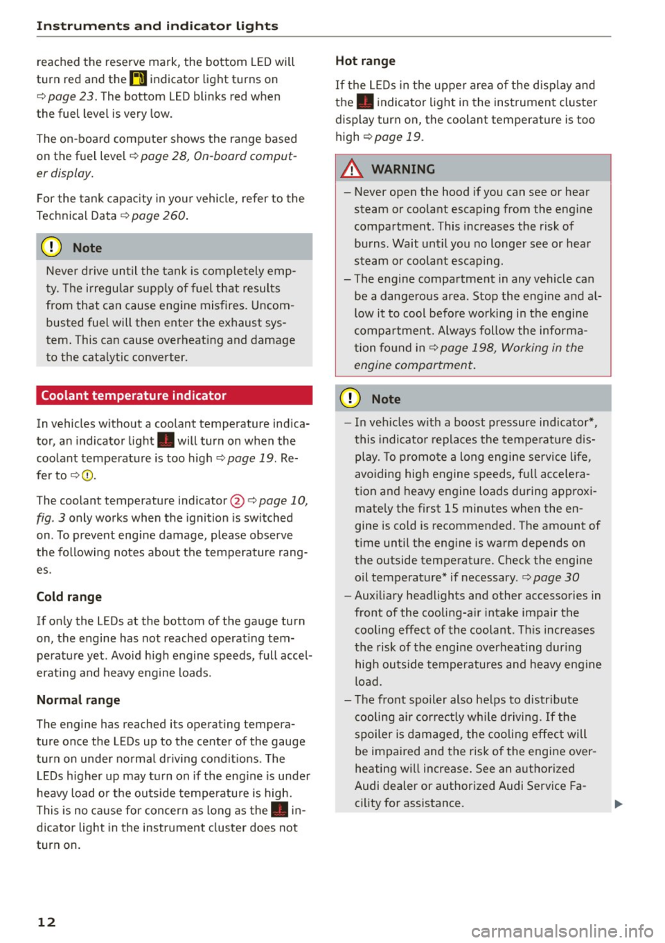
Coolant temperature indicator
In vehicles without a coolant temperature indica
tor, an indicator light. will turn on when the
coolant temperature is too high ¢
page 19. Re
fer to ¢(1) .
The coolant temperature indicator @c:>
page 10,
fig . 3 only works when the ignition is switched
on . To prevent engine damage, please observe
the following notes about the temperature rang
es.
Cold range
If only the LEDs at the bottom of the gauge turn
on, the engine has not reached operating tem perature yet. Avoid high engine speeds, full accel
erating and heavy engine loads.
Normal range
The engine has reached its operating tempera
ture once the LEDs up to the center of the gauge
turn on under normal driving conditions . The
LEDs higher up may turn on if the engine is under
heavy load or the outside temperature is high.
This is no cause for concern as long as the. in
dicator light in the instrument cluster does not
turn on.
12
Hot range
If the LEDs in the upper area of the display and
the . indicator light in the instrument cluster
display turn on, the coolant temperature is too
high
c:> page 19 .
A WARNING
-Never open the hood if you can see or hear
steam or coolant escaping from the engine
compartment. This increases the risk of
burns. Wait until you no longer see or hear
steam or coolant escaping.
- The engine compartment in any vehicle can
be a dangerous area . Stop the engine and al
low it to cool before working in the engine
compartment. Always follow the informa
tion found in ¢
page 198, Working in the
engine compartment.
(D Note
- In vehicles with a boost pressure indicator* ,
this indicator replaces the temperature dis
play. To promote a long engine service life,
avoiding high engine speeds, full accelera
tion and heavy engine loads during approxi
mately the first 15 minutes when the en
gine is cold is recommended . The amount of
time until the engine is warm depends on
the outside temperature . Check the engine
oil temperature* if necessary .
c:> page 30
-Auxiliary headlights and other accessories in
front of the cooling-air intake impair the
cooling effect of the coolant. This increases
the risk of the engine overheating during
high outside temperatures and heavy engine
load.
- The front spoiler also helps to distribute
cooling air correctly while driving. If the
spoiler is damaged, the cooling effect will
be impaired and the risk of the engine over
heating will increase. See an authorized
Audi dealer or authorized Audi Service Fa
cility for assistance.
Page 15 of 282
....,
N
0 > co
rl I.O
"'
"'
"'
rl
@ Tips
Diesel engines: Due to the high efficiency of
these engines, the engine may not a lways
reach operating temperature in cold outside
temperatures. This is normal and not a cause
for concern.
Indicator lights
Description
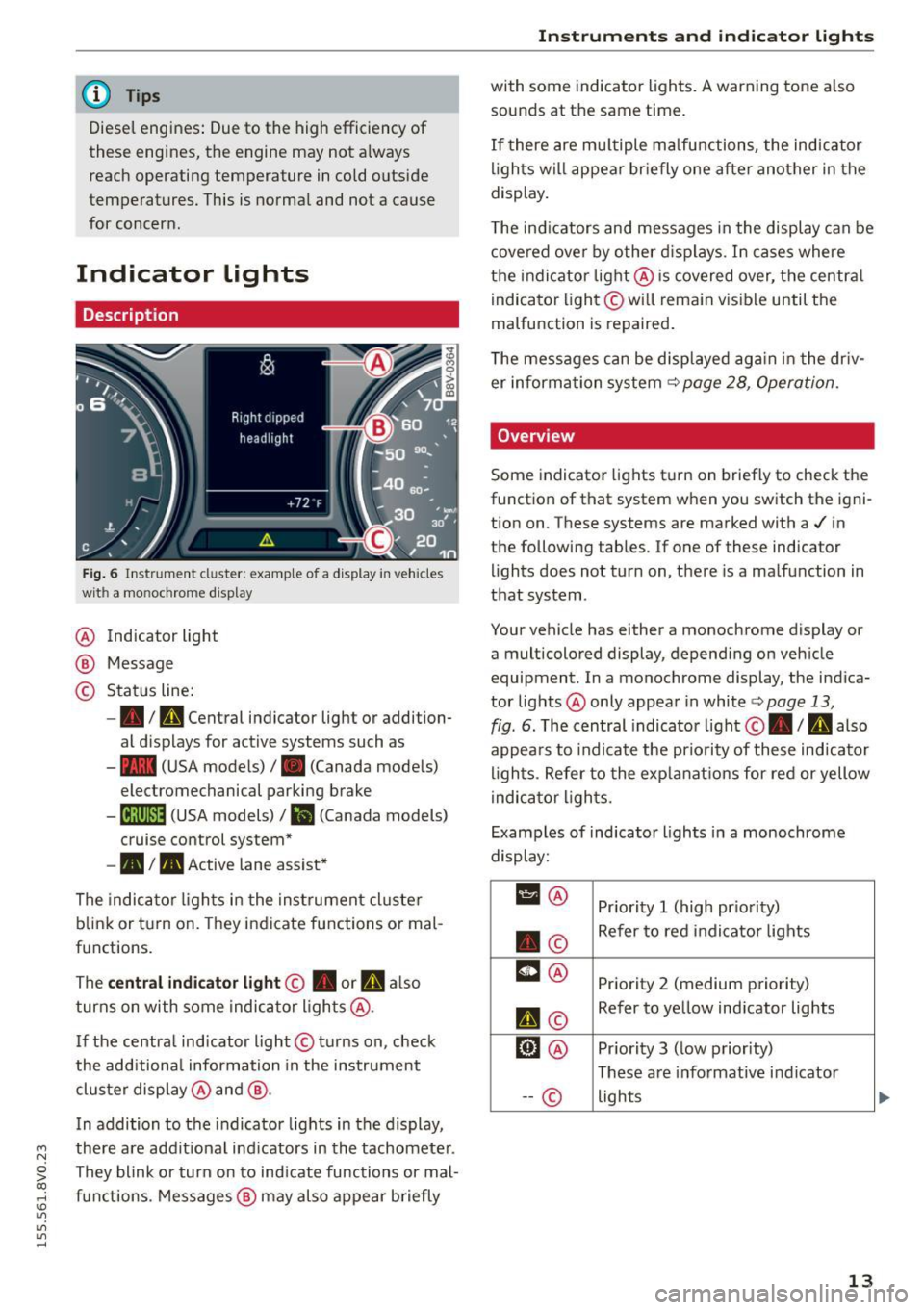
Fig. 6 Instrument cl uster : example of a d isplay in vehicles
wit h a mo noc hro me display
@ Indicator light
® Message
© Status line:
-• ID Central indicator light or addition
al d isplays for active systems such as
- - (USA models)
I. (Canada models)
electromechanical parking brake
- [ij;(i)~14 (USA models) / Iii (Canada models)
cruise control system*
- • I. Active lane assist*
The indicator lights in the instrument cluster
blink or turn on. They indicate functions or mal
functions.
The
central indicator light@ • or a also
turns on with some indicator lights@.
I f the centra l indicator light @turns on, check
the additiona l information in the instrument
cluster display @ and @.
In addition to the indicator lights in the display,
there are add it ional ind icators in the tachometer .
They blink or turn on to ind icate functions or mal
functions. Messages @ may also appear briefly
Instruments and indicator lights
with some indicato r lights. A warning tone a lso
sounds at the same time.
If t here are mult iple malfunctions, the indicator
lights will appear br iefly one after another in the
display.
T he ind icators and messages in the display can be
covered over by other displays . In cases where
the indicator light @is covered over, the centra l
indicator light@will remain visible until the
malfunction is repaired .
T he messages can be displayed again in the driv
er information system
~ page 28, Operation.
Overview
Some indicator lights turn on briefly to check the
function of that system when you switch the igni
tion on . These systems are marked with a./ in
the following tables. If one of these indicator lights does not turn on, there is a malfunction in
that system .
Your vehicle has either a monochrome display or a multicolored display, depending on vehicle
equipment . In a monochrome display, the indica
tor lights @ only appear in white
Q page 13,
fig . 6. The central indicator light ©. / D also
appea rs to indicate the prio rity of these indicator
lights. Refer to the explanations for red or yellow
indicator lights.
Examples of indicator lights in a monochrome
display:
11 @ Priority 1 (high priority)
. © Refer to
red indicator lights
m@ Pr iority 2 (medium priority)
II ©
Refer to yellow indicator lights
D@ Pr iority 3 (low priority)
These are i nformative indicator
-- © lights
13
Page 16 of 282
Instruments and indicator lights
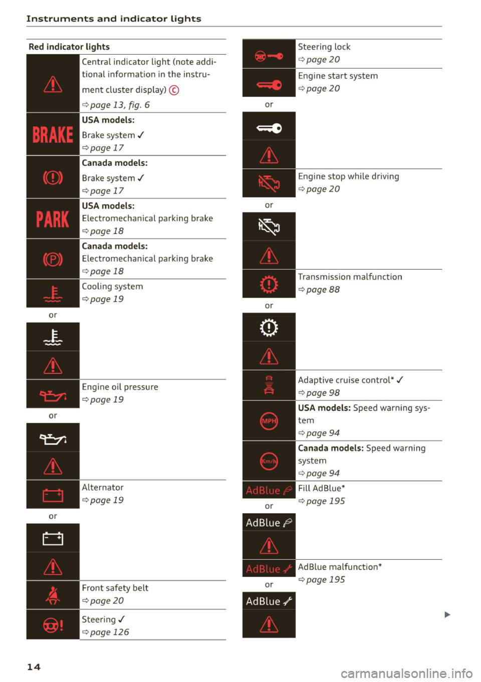
Red indicator light s
or
or
or
14
Central indicator light (note addi-
tional informat ion in the instru-
ment cluster display) ©
<=>page 13, fig. 6
USA m odel s:
Brake system ../
<=>page 17
Cana da models :
Brake system ../
<=>page 17
USA models :
Electromechan ical parking brake
<=> page 18
Canada mod els :
Electromechanica l parking b rake
<=> page 18
Cooling system
<=>page 19
Eng ine oil pressure
<=>page 19
Al ternator
<=>page 19
Fr ont safety belt
<=>page20
S teer ing../
<=>page 126
or
or
or
or
or Steering lock
<=>
page20
Engine start system
<=> page20
Engine stop whi le driving
<=> page 20
Transmission malfunction
<=>page 88
Adaptive cruise control*./
<=>page 98
USA mod els: Speed warning sys
tem
<=> page 94
Canada mo del s: Speed warning
system
<=> page 94
Fill Ad Blue*
<=> page 195
AdB lue malfunct ion*
<=> page 195
Page 24 of 282
Instruments and indicator lights
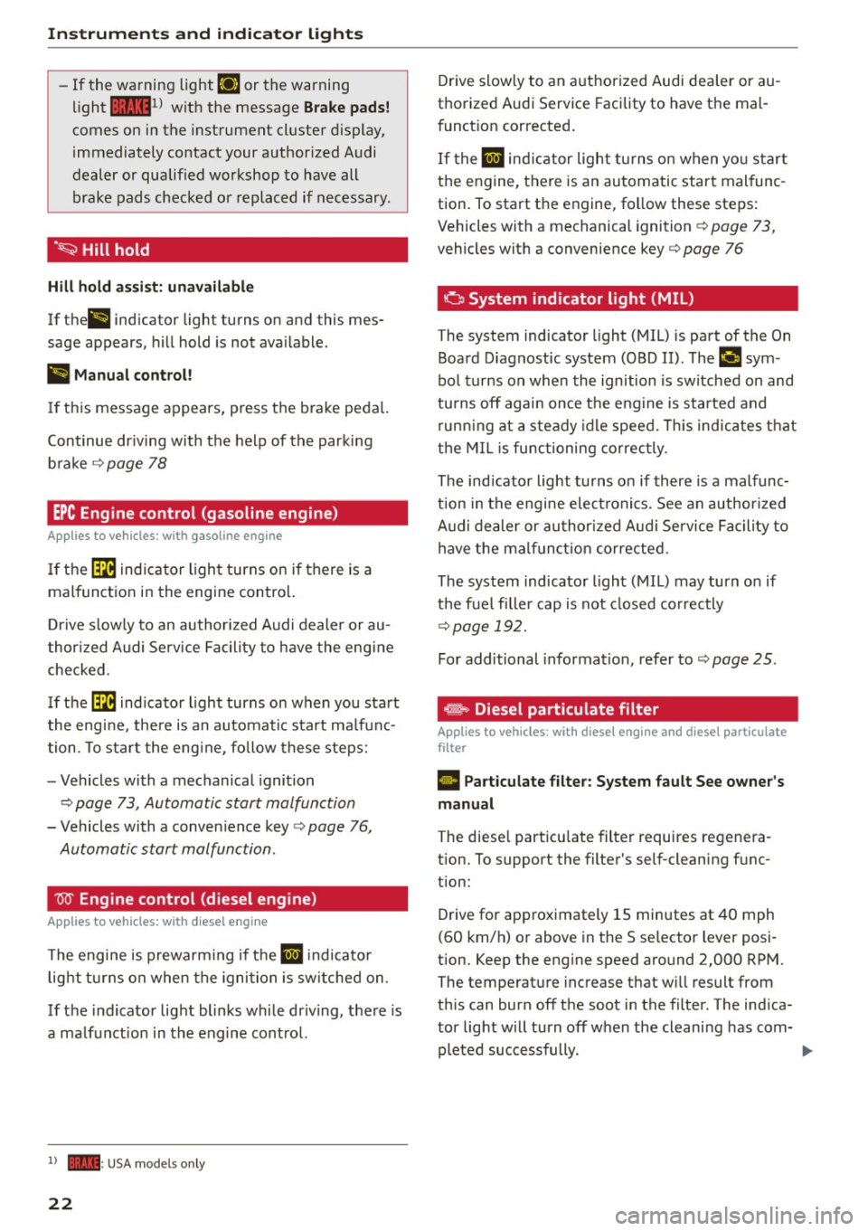
-If the warnin g light EiJ or the warning
light
11111 ) w ith the message Brake p ads!
comes on in the instrument cluster display,
immediately contact your author ized Audi
dealer or qualified workshop to have all
brake pads checked o r replaced if necessary.
·~ Hill hold
Hill hold assi st: unavailable
If the ll ind icator light turns on and this mes
sage appears, hill hold is not ava ilable.
II Manual control!
If thi s message appears, press the b rake peda l.
Continue dr iv ing with the help of the parking
b ra ke
¢ page 78
EPC Engine control (gasoline engine)
A pp lies to veh icles: w ith gaso line engine
If th e ~ indica tor ligh t turns on if there is a
malfunct ion in the engine contro l.
D rive s low ly to an author ized A udi dealer or au
thor ized Audi Se rv ice Facility to have the eng ine
checked.
I f the ~ indicator light turns on when you sta rt
the eng ine, the re is an automatic start ma lf u n c
tion. To sta rt the eng ine, fo llow these steps:
- Vehicles with a mechanical igni tion
c:> page 73, Automatic start malfunction
- Vehicles with a conven ience key c:> page 76,
Automatic start malfunction .
W Engine control (diesel engine)
A pp lies to veh icles: w ith d iesel e ngi ne
T he engine is prewa rming if t he II indicato r
light t urns on when the igni tion is sw itched on .
If the indicator lig ht blinks while dr iv ing , th e re is
a ma lfunct ion in the engine cont ro l.
l) - : USA mode ls onl y
22
Drive slowly to an a uthorized Audi dea ler or au
thorized Audi Service Facility to have the mal
funct ion corrected .
I f the
II ind ic a tor light tu rns on w hen yo u start
t h e engine, t here is a n automatic start mal func
tion . To start the engine, follow these ste ps:
Vehicles with a mechanical ignition ¢
page 73,
vehicles with a convenience key c:> page 76
o System indicator light (MIL )
The system indicator light (MIL) is part of the On
Board Diagnostic system (OBD II). ThP
¢..ifi sym
bo l turns on whe n the ignition is switched on and
tu rns off agai n once t he eng ine is started and
r un ning at a steady id le speed. This ind ic a te s th at
t h e MIL i s func tioning correc tly.
The ind icator light turns on if there is a malfunc
t ion in t he engine electronics. See an author ized
A udi de aler or au thori zed A udi Service Faci lity to
h ave the mal funct io n corrected.
The system indicato r light (MIL) may turn o n if
the f ue l filler cap is not closed co rrectly
¢page 192.
For additional information, refer to c:> page 25.
... Diesel particulate filter
Applies to vehicles : wit h diese l eng ine a nd diese l particulate
filter
• Part iculate filter: System fault See owner's
manual
The diese l part icu late filter requires regenera
tion. To support the filter's self-cleaning f unc
tion:
D rive for app roximately 15 minutes at 40 mph
(60 km/h) o r above in the S se lector lever posi
tion. Keep the eng ine speed around 2,000 RP M.
The temperat ure increase that w ill result from
th is can burn off the soot in the filter. The ind ica
tor light w ill turn off when the cleani ng has com-
pleted successfully. .,..
Page 27 of 282
....,
N
0 > co
rl I.O
"'
"'
"'
rl
continue to turn the lights on and off using the
light switch. You can still contro l all wiper func
tions that are independent of the rain sensor .
Drive to an autho rized Aud i dea le r or authorized
Audi Service Facility immediate ly to have the
malfunction corrected.
; Adaptive dampers
Applies to vehicles: with Audi drive select
R Suspension: system fault!
There is an adaptive damper ma lfunction.
D rive to an authorized Aud i dea ler or a uthorized
Aud i Service Facility immediate ly to have the
malfunction corrected.
¢¢Turn signals
If the B or DI indicator light blinks, a turn sig
na l is turned on. If both indicator lig hts are blink
ing, the emergency flashers are on.
I n an indicator light blinks twice as fast as usual
then a blinker bulb has failed. Carefully drive to
your authorized Audi dealer immed iate ly to have
the ma lfunction corrected.
(D Tips
For more information on the turn signals, re
fer to
q page 45.
On-Board Diagnostic
system (OBD)
System indicator light (MIL)
The system indicator light (MIL) ¢4 in the instru
ment cluster is part of the On Board Diagnostic
System (OBD II).
The warning/indicator light turns on when the ig nition is switched on and turns off once the en
gine is started and is running in idle at a stab le
speed. Th is ind icates that the MIL is funct ion ing
correctly .
If the light does not turn off after starting the
engine
or turns on while driving, this may indi
cate there is a ma lfunction in the engine. If the
Instruments and indicator lights
indicator turns on, the cata lytic conve rter may be
damaged.
Drive
with reduced engine performance (avoid
high speeds for extended per iods of time and/or
f ast acceleration) and have the malfunction cor
rected . See an authorized Audi dealer or author
ized Audi Serv ice Facility.
T he indicator may turn on if the e lectronic speed
limiter is faulty. For add itiona l information, refer
to
¢ page 94, Electronic speed limiter*.
The MIL may also turn on if the fuel filler cap is
not closed correctly ¢
page 192.
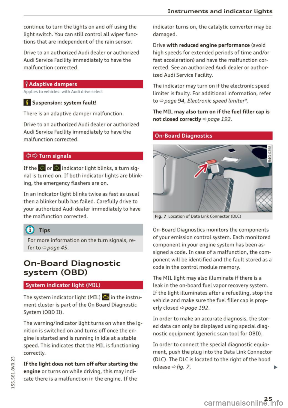
On-Board Diagnostics
Fig. 7 Location of Data Link Connector (DLC)
On-Board Diagnostics monitors the components
of your emission control system. Each monitored
component in your engine system has been as
s igned a code . In case of a mal function, the com
ponent will be identified and the fault stored as a
code in the control module memory.
T he M IL light may also illuminate if there is a
leak in the on-board fuel vapor recove ry system.
If the light illuminates after a refuelling, stop the
vehicle and make sure the fuel filler cap is prop
erly closed
qpage 192.
In order to make an accurate diagnosis, the stor
ed data can only be displayed using special diag
nostic equipment (generic scan tool for OBD).
In order to connect the special diagnostic equip
ment, push the plug into the Data Link Connector
(DLC). The DLC is located to the right of the hood
release
¢ fig. 7. ..,.
25
Page 32 of 282
Driver information system
program is deleted ¢page 29, the values in the
on-board computer 1 are also reset.
Other equipment
Applies to vehicles: with driver information system
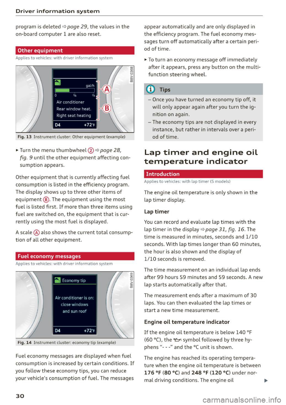
Fig. 13 Instrument cluster: Other equ ipment (examp le)
"'T urn the menu thumbwheel @ ¢ page 28,
l8 M 0
>
"' a,
fig. 9 until the other equipment affecting con
sumption appears.
Other equipment that is currently affecting fuel
consumption is listed in the efficiency prog ram.
The display shows up to three other items of
equipment @. The equipment using the most
fue l is listed first. If more than three items using
fuel are switched on, the equ ipment that is cur
rently using the most fuel is displayed.
A scale @ also shows the current total consump
tion of all other equipment.
Fuel economy messages
Applies to vehicles: with driver information system
Fig. 14 Instrument cluster: economy tip (example)
Fuel economy messages are disp layed when fuel
consumption is increased by certain conditions . If
you follow these economy tips, you can reduce
your veh icle's consumption of fuel. The messages
30
appear automatically and are only disp layed in
the efficiency program. The fuel economy mes
sages turn off automatically after a certain per i
od of t ime.
"'T o turn an economy message off immediate ly
after it appears, press any button on the multi
function steering wheel.
(D Tips
- Once you have turned an economy tip off, it
wi ll only appear again after you turn the ig
nition on again.
- The economy tips are not displayed in every
instance, but rather in intervals over a peri
od of time.
Lap timer and engine oil
temperature indicator
Introduction
Applies to veh icles: with lap tim er (S models)
The engine oil temperature is only shown in the
lap timer display.
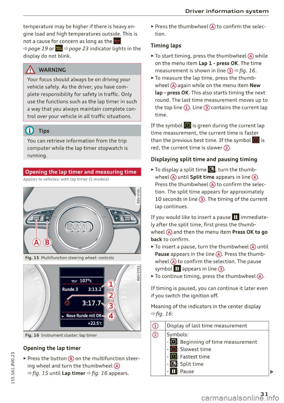
Lap timer
You can record and evaluate lap times with the
l ap timer in the display¢
poge 31, fig. 16. The
time is measured in minutes, seconds and 1/10
seconds. With lap times longer than 60 minutes,
the hour is also shown and the display of
1/10 seconds is removed.
The time measurement on an individua l lap ends
after 99 hours 59 minutes and 59 seconds. A new
lap starts automatically after that.
The meas urement ends after a maximum of 30
laps. You can then eva luated the lap times or
start a new time measurement.
Engine oil temperature indicator
If the engine oil temperature is below 140 °F
(60 °C), the~ symbol followed by three hy
phens" ---" and the °C unit is shown .
The engine has reached its operating tempera
ture when the engine oil tempera ture is between
176 °F (80 °() and 248 °F (120 °C) under nor-
mal driving conditions. The engine oil
IJI>
Page 33 of 282
....,
N
0 > co
rl I.O
"'
"'
"'
rl
temperature may be higher if there is heavy en
gin e load and high temperatures outside. This is
not a cause for concern as long as the.
¢page 19 orllll ¢page23 indicator lights in the
display do not blink.
A WARNING
Your focus should always be on driving your
vehicle safely . As the dr iver, you have com
plete responsibility for safety in traffic . Only
use the functions such as the lap timer in such
a way that you a lways maintain complete con
trol over your vehicle in all traffic situations .
(D Tips
You can retr ieve information from the tr ip
computer while the lap timer stopwatch is
r u nning.
Opening the lap timer and measuring time
Applies to vehicles: with lap timer (5 models)
Fig. 15 Multifunction steer ing wheel: controls
Fig. 16 Instrument cluster: lap timer
Opening th e lap timer
-
"'Press the button @ on the multifunction steer
ing wheel and turn the thumbwheel @
¢fig. 15 unt il Lap timer ¢fig. 16 appea rs.
Dr iver inform atio n sy stem
.. Press the thumbwheel @ to confirm the selec
tion.
T im ing laps
"' To sta rt timing, press the thumbwheel @ while
on the menu item
Lap 1 - pre ss OK . The time
measurement is shown in line @
r=:> fig. 16.
.. To measure the lap time, press the thumb
wheel @ again while on the men u item
New
lap -pre ss O K. This also starts timing the next
round. The last time measurement moves up to
the top line
(D . Line ® contains the current lap
time .
If the symbol
ri) is green during the current lap
t ime measurement, the current time is faster
than the previous best time. If the symbol. is
red, the current time is slower @.
Displaying split time and pausing tim ing
.. To display a split time
[~l turn the thumb-
wheel @until
Split time appears in line @.
Press the thumbwheel @ to confirm the selec
tion. The split time appears for approximately 10 seconds in line @. The timing of the current
lap conti nues.
If you would like to insert a pause
m immediate
ly after the split t ime, first press the thumb
wheel @and then the menu item
Pr ess OK to go
back to confirm .
"' To insert a pause, turn the thumbwheel @ until
Pau se appears in the line @. Press the thumb
wheel @ to confirm the se lec tion . Th e pause
symbo l
m appears in line @ .
.. To continue timing, press the thumbwhee l@ .
If timing is paused , you can continue it la ter even
i f you sw itch the ignition off.
Mean ing of the indicators in the center d isp lay
¢ fig . 16:
CD Disp lay of last time measurement
@ Symbols:
-
[O]: Begin ning of time measuremen t
- . : Slowest time
- . : Fastest time
- [~]: Split time
-m : Pause
31
Page 46 of 282
Light and Vision
When switched on, adaptive light adjusts to
curves depending on the vehicle speed and steer·
ing wheel angle . This provides better lighting
through the curve. The system operates in a
speed range from approximately 6 mph (10 km/
h) to 68 mph (110 km/h).
Static cornering light* (vehicles with adaptive
light)· the cornering light switches on automati
cally when the steering wheel is turned at acer
tain ang le at speeds up to approximately 44 mph
(70 km/h) and whe n the turn signal is activated
at speeds up to approximately 25 mph (40 km/
h). The area to the side of the vehicle is illuminat
ed better when tu rning.
Speed depend ent light distribution* -The speed
dependent light distribution adapts the light in
towns and on highways or expressways. In tersec
tions can also be illum inated on veh icles with a
navigat ion system*.
Highway light function*
(Vehicles with adaptive light or LED headlights) -
This function adapts the light ing for highway
driving based on vehicle speed .
..&, WARNING
-Automatic headlights* are only int ended to
assist the driver. They do not relieve the
driver of his responsibility to check the
headlights and to turn them on manually
according to the current light and visibi lity
condit ions. For example, fog cannot be de·
tected by the light sensors . So always switch
on the low beam under these weather con
ditions and when driving in the dark
io.
- Accidents could occur if you can not see the
road ahead of you well and if others on the
road cannot see you . Always switch your
head lightsonsothatyoucanseetheroad
ahead of you and others can see your vehicle
from behind.
- Please observe legal regulations when using
the lighting systems described .
44
(D Note
The rear fog lights shou ld only be turned on in
accordance with traffic regulation, as the lights are bright for following traffic.
@ Tips
-The light sensor for the automatic head
lights * is in the rearview mirror mount.
Therefore, do not place any stickers in this
area on the windshield.
- Some functions of the exterior lighting can
be adjusted
c> page 45.
- If you turn off the ignition whi le the exterior
lights are on and open the door, you will
hear a warning tone.
- In some market-specific versions, the tail
lights do not turn on when switching on the
daytime running lights.
- In cool or damp weather, the inside of the headlights, turn signals and taillights can
fog over due to the temperature difference
between the inside and outside . They will
clear shortly after switching them on. This
does not affect the serv ice life of the light
ing .
- A message will appear in the instrument
cluster if there is a malfunction in the light
sensor
c> page 24.
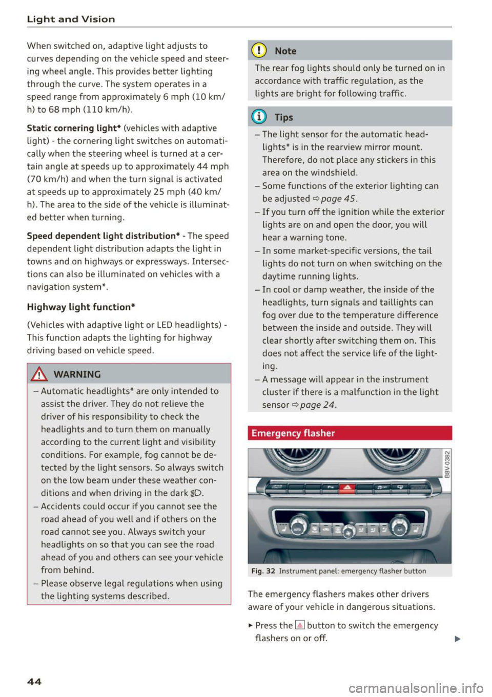
Emergency flasher
Fig. 32 Ins trumen t panel : em ergenc y flasher bu tton
The emergency flashers makes other dr ivers
aware of your vehicle in dangerous s ituations .
.. Press the~ button to switch the emergency
flashers on or off.