transmission oil AUDI S3 SEDAN 2015 Owners Manual
[x] Cancel search | Manufacturer: AUDI, Model Year: 2015, Model line: S3 SEDAN, Model: AUDI S3 SEDAN 2015Pages: 282, PDF Size: 71.14 MB
Page 16 of 282
Instruments and indicator lights
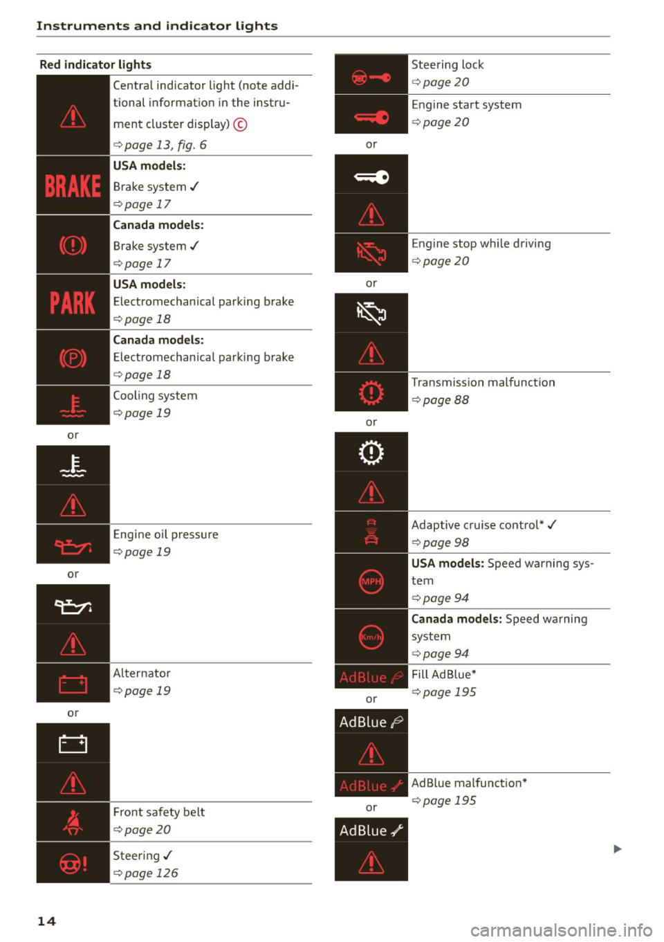
Red indicator light s
or
or
or
14
Central indicator light (note addi-
tional informat ion in the instru-
ment cluster display) ©
<=>page 13, fig. 6
USA m odel s:
Brake system ../
<=>page 17
Cana da models :
Brake system ../
<=>page 17
USA models :
Electromechan ical parking brake
<=> page 18
Canada mod els :
Electromechanica l parking b rake
<=> page 18
Cooling system
<=>page 19
Eng ine oil pressure
<=>page 19
Al ternator
<=>page 19
Fr ont safety belt
<=>page20
S teer ing../
<=>page 126
or
or
or
or
or Steering lock
<=>
page20
Engine start system
<=> page20
Engine stop whi le driving
<=> page 20
Transmission malfunction
<=>page 88
Adaptive cruise control*./
<=>page 98
USA mod els: Speed warning sys
tem
<=> page 94
Canada mo del s: Speed warning
system
<=> page 94
Fill Ad Blue*
<=> page 195
AdB lue malfunct ion*
<=> page 195
Page 91 of 282
....,
N
0 > co
rl I.O
the malfunction corrected. If the indicator light
and the driver message do not turn off, do not
continue dr iv ing. See an authorized Audi dealer
or authorized Audi Service Facility for assistance .
rm Transmission malfunction: you can continue
driving
Drive to an authorized Aud i dealer or authorized
Aud i Service Facility immediately to have the
malfunction corrected.
rm Transmission malfunction: no reverse gear
(you can continue driving)
Drive to an authorized Aud i dealer or authorized
Audi Service Fac ility immediately to have the
malfunction corrected.
rm Transmission malfunction: You can continue
driving in D until engine off
Drive the vehicle away from moving traffic and
park. See an authorized Audi dealer or authorized
Audi Service Fac ility for assistance.
rm Transmission overheating! Please adapt
driving style
Continue driving moderate ly. When the indicator
light turns off, you can continue driving normally.
rm Transmission: Please press brake pedal and
select gear again
If the transmission malfunctions because the
temperature is too high, a message appears
when the transmission is coo led.
Selector lever emergency re lease
Appl ies to vehicles: with S tronic transm ission
If the vehicle's power supply foils, the selector
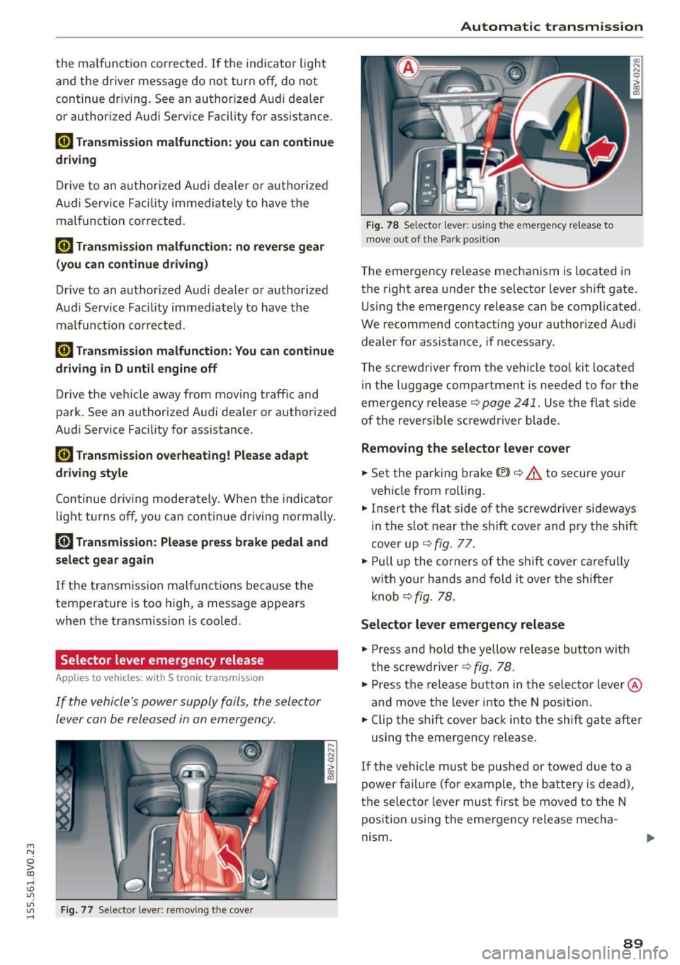
lever can be released in an emergency.
"'
"'
"' Fig. 77 Selector lever: removing the cove r rl
Automatic transmission
Fig. 78 Selector lever: u sing the emergency release to
move out of the Park position
The emergency release mechanism is located in
the right area under the selector lever shift gate.
Using the emergency release can be complicated.
We recommend contacting your authorized Audi dealer for assistance, if necessary.
The screwdriver from the vehicle too l kit located
in the luggage compartment is needed to for the
emergency release
c> page 241. Use the flat side
of the reversible screwdriver blade .
Removing the selector lever cover
.. Set the parking brake «Ell c> A to secure your
vehicle from rolling.
.. Insert the flat side of the screwdriver s ideways
in the slot near the shift cover and pry the shift
cover up ¢
fig. 77 .
.. Pull up the co rners of the sh ift cover carefully
with your hands and fo ld it over the shifter
knob ¢
fig. 78.
Selector lever emergency release
.. Press and hold the yellow release button with
the screwdriver ¢
fig. 78.
.. Press the release button in the selector lever ®
and
move the lever into the N position.
.. Clip the shift cover back into the shift gate after
using the emergency release.
If the vehicle must be pushed or towed due to a
power failure (for example, the battery is dead),
the selector lever must first be
moved to the N
position using the emergency release mecha
nism .
89
Page 252 of 282
Fuses and bulbs
No. Equipment
F49 Starter, clutch sensor,
headlight relay coil
F53 Rear window defogger
The power seats* are protected via
circuit break
ers
that automatically switch on after a few sec
onds after the overload has been reduced.
(0 Tips
Note that the following table was accurate at
the time of printing and is subject to change.
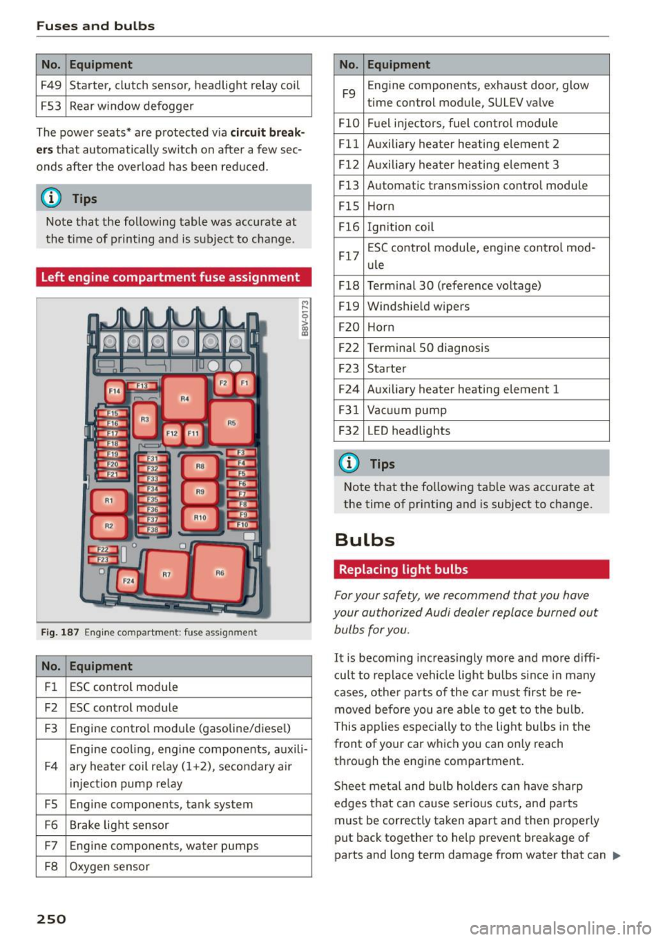
Left engine compartment fuse assignment
Fig. 187 Engine compartmen t: fuse assig nme nt
No. Equipment
Fl ESC control module
F2 ESC control module
F3 Engine control module (gasoline/diesel)
Engine cooling, engine components, auxili-
F4 ary heater coil relay (1+2), secondary a ir
injection pump relay
FS Engine components, tank system
F6 Brake light sensor
F7 Engine components, water pumps
F8 Oxygen sensor
250
No. Equipment
F9 E
ngine components, exhaust door, glow
time control module, SULEV valve
Fl0 Fuel injectors, fuel control module
Fll Auxiliary heater heating element 2
F12 Auxiliary heater heating element 3
F13 Automatic transmission control module
FlS Horn
F16 Ign ition coil
F17 ESC
control module, engine contro l mod-
ule
F18 Terminal 30 (reference voltage)
F19 Windshie
ld wipers
F20 Horn
F22 Terminal 50 diagnosis
F23 Starter
F24 Auxiliary heater heating element 1
F31 Vacuum pump
F32 L
ED headlights
(!') Tips
Note that the following tab le was accurate at
the time of printing and is subject to change.
Bulbs
Replacing light bulbs
For your safety , we recommend that you have
your authorized Audi dealer replace burned out
bulbs for you.
It i s becoming increasingly more and more diffi
cu lt to replace vehicle light bulbs s ince in many
cases, other parts of the car must first be re
moved before you are able to get to the bulb.
This applies especially to the light bulbs in the
front of your car which you can only reach
through the engine compartment.
Sheet meta l and bulb holders can have sharp
edges that can cause serious cuts, and pa rts
must be correctly taken apart and then properly
put back together to help prevent breakage of
parts and long term damage from water that can .,,_
Page 259 of 282
M N
0 > co ,...., \!) 1.1"1
1.1"1
1.1"1
,....,
such as the engine b lock or transmission
are removed .
- When removing heavy components like
these, anchor vehicle to ho ist o r add corre
sponding weights to maintain the center of
gravity . Otherwise, the vehicle might tilt or
s li p off the hoist , causi ng se rious pe rsonal
injury .
([) Note
-Be awa re of the fo llowing points befo re lift
i ng t he ve hicle:
-The vehicle should never be lifted or
jacked up from underneath the engine oil pan, the transmission housing, the front
or rear axle or the body side members.
This could lead to serious damage.
- To avoid damage to the underbody or
chassis frame , a rubber pad must be in·
serted between the floo r jack and the lift
points.
- Before driving over a wo rkshop hoist,
check that the veh icle weight does not
e xceed the permiss ible lift ing capacity of
the hoist.
- Before driv ing over a workshop hoist, en
sure that there is sufficient clearance be
tween the hoist and low parts of the ve
hicle .
Emergency s ituations
257
Page 260 of 282
Technical data
Technical data
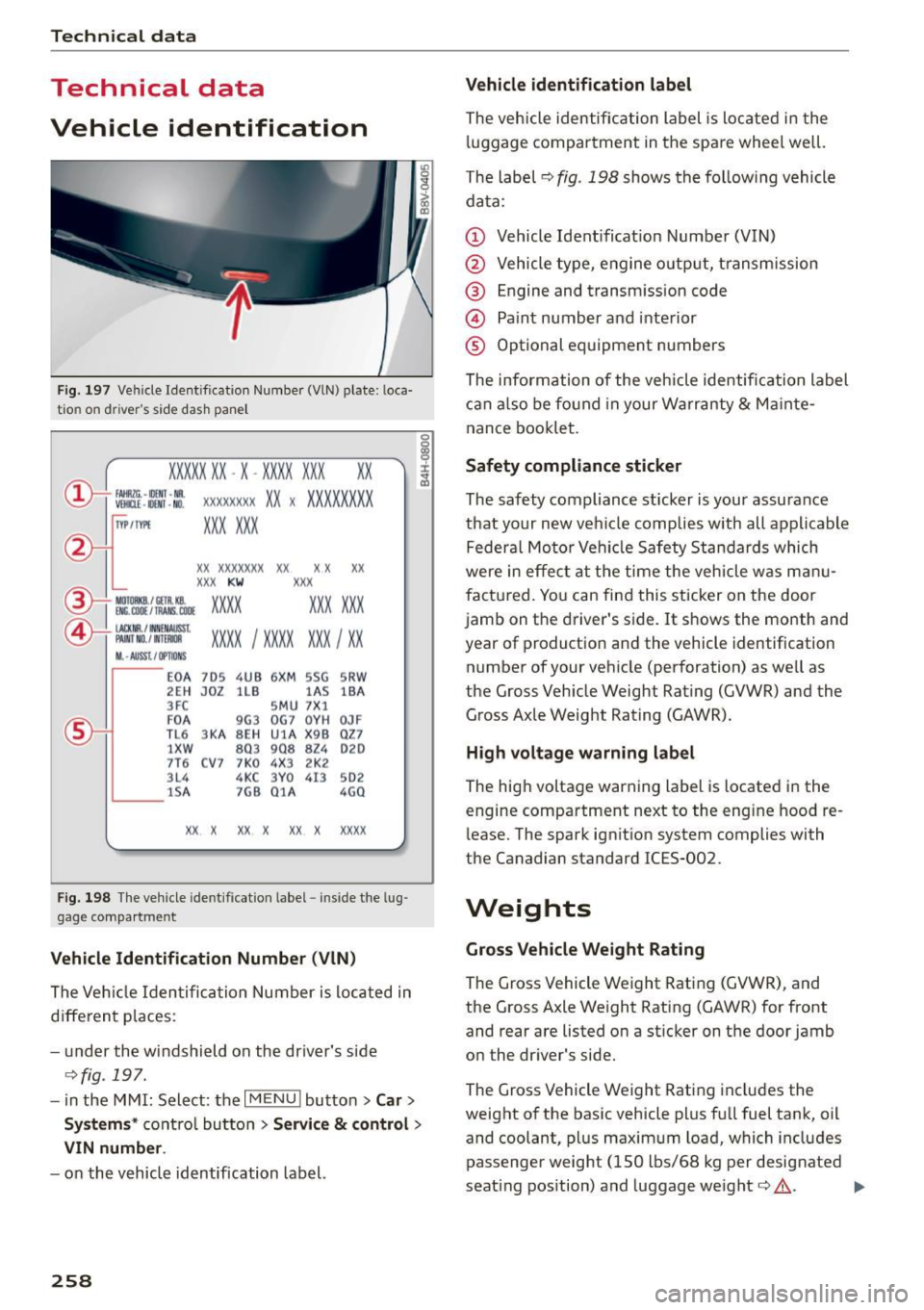
Vehicle identification
F ig. 197 Ve hicle Ident if icat ion Number (VlN) p late: loca·
tio n on d river 's side dash pane l
XXXXX XX -X -XX XX XXX XX
@-+ ~J:~t::1 ::: xxxxxxxx xx x xxxx xxx x
IYP lf'VPE XXX X XX
XX XXXXXXX XX X X XX
XXX KW XXX
\YT IM:.COll/fAANS ,COOE XXX XXX 15\_L I MOIOlll
@-+ ~~
1
:tr:~i XXXX I XXXX XXX I XX
II. -AUSST . / OPTIO NS
EO A 7D5 4UB 6X
M SSG SR W
2EH JOZ lLB lAS
1BA
3FC SM U 7 X1
FO A
9G3 O
G7 OY H
OJF
TL 6 3 KA BEH UlA X 9B Q
Z7
l XW
803 908
8Z4 020
7T6 C V7 7 KO 4X3 2K2
3L4 4KC 3YO 413
502
lS A 7GB 01A
4GO
XX X XX X
XX X xxxx
Fig. 198 The ve hicle ide ntif ic ati on label - inside t he lug ·
gage compar tmen t
Vehicle Identificat ion Number (VlN )
The Veh icle Iden tifica tion Number is located in
differen t places :
- u nder the windshield on the driver's side
¢ fig . 197.
- in the MMI: Select: the I MENU I button> Car >
System s* cont ro l button > Service & control >
VIN number .
-on the vehicl e identification label.
258
Vehicle identification label
The vehicle identification label is located i n the
l uggage compartment in the spare whee l we ll.
The label
9 fig . 198 shows the follow ing vehicle
da ta:
(D Vehicle Ident ificat ion Number (VIN)
@ Vehicle type, engine o utput, transmission
@ Engine and transm ission code
@ Pa int number and interior
® Optional equipment numbers
The information of the vehicle identification label
can also be fo und in your Warranty
& Ma inte
nance booklet.
Safety complianc e sticker
The safety compliance sticker is your assurance
that your new vehicle complies with all applicable
Federa l Mo to r Ve hicl e Safety Standards which
were in e ffect at the time the vehicle w as m anu
factured. You can find this sticker on the door
jamb on the d river's s ide. It shows the month and
year of production and the vehicle identification number of your veh icle (perforation) as we ll as
the Gross Veh icle Weight Rating (GVWR) and the
Gross Axle Weight Rating (GAWR).
H igh volt age warning label
The hig h voltage warning label is located i n the
engine compartment next to the engine hood re
l ease. The spark ignition system complies with
the Canadian standard ICES-002 .
Weights
Gross Vehicle Weight Rating
The Gross Vehicle Weight Rating (GVWR), and
the Gross Axle We ight Rating (GAWR) for front
and rear are listed on a st icker on the door jamb
o n the dr iver 's side.
The Gross Vehicle Weight Rating includes the
weight of the basic vehicle plus fu ll fuel tank, oil
and coolant, plus maxim um load, which includes
passenger weight (150 lbs/68 kg per designated
seat ing pos ition) and luggage weight ¢,&. . ..,_