ignition AUDI S4 1998 B5 / 1.G Engine Manual
[x] Cancel search | Manufacturer: AUDI, Model Year: 1998, Model line: S4, Model: AUDI S4 1998 B5 / 1.GPages: 72, PDF Size: 3.25 MB
Page 53 of 72

54
Sensors
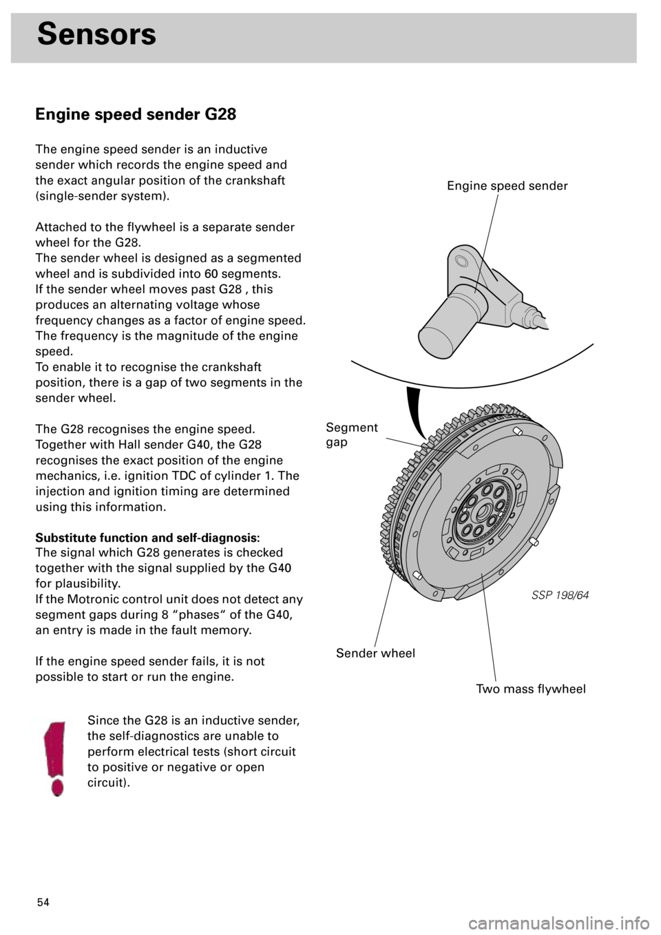
Engine speed sender G28
The engine speed sender is an inductive
sender which records the engine speed and
the exact angular position of the crankshaft
(single-sender system).
Attached to the flywheel is a separate sender
wheel for the G28.
The sender wheel is designed as a segmented
wheel and is subdivided into 60 segments.
If the sender wheel moves past G28 , this
produces an alternating voltage whose
frequency changes as a factor of engine speed.
The frequency is the magnitude of the engine
speed.
To enable it to recognise the crankshaft
position, there is a gap of two segments in the
sender wheel.
The G28 recognises the engine speed.
Together with Hall sender G40, the G28
recognises the exact position of the engine
mechanics, i.e. ignition TDC of cylinder 1. The
injection and ignition timing are determined
using this information.
Substitute function and self-diagnosis:
The signal which G28 generates is checked
together with the signal supplied by the G40
for plausibility.
If the Motronic control unit does not detect any
segment gaps during 8 “phases“ of the G40,
an entry is made in the fault memory.
If the engine speed sender fails, it is not
possible to start or run the engine.
Since the G28 is an inductive sender,
the self-diagnostics are unable to
perform electrical tests (short circuit
to positive or negative or open
circuit).
SSP 198/64
Two mass flywheel
Sender wheel
Engine speed sender
Segment
gap
Page 55 of 72

56
Sensors
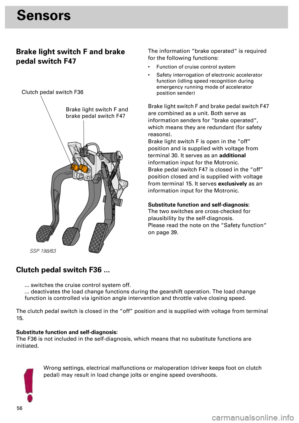
Brake light switch F and brake
pedal switch F47The information “brake operated“ is required
for the following functions:
• Function of cruise control system
• Safety interrogation of electronic accelerator
function (idling speed recognition during
emergency running mode of accelerator
position sender)
Brake light switch F and brake pedal switch F47
are combined as a unit. Both serve as
information senders for “brake operated“,
which means they are redundant (for safety
reasons).
Brake light switch F is open in the “off”
position and is supplied with voltage from
terminal 30. It serves as an additional
information input for the Motronic.
Brake pedal switch F47 is closed in the “off”
position closed and is supplied with voltage
from terminal 15. It serves exclusively as an
information input for the Motronic.
Substitute function and self-diagnosis:
The two switches are cross-checked for
plausibility by the self-diagnosis.
Please read the note on the “Safety function“
on page 39.
Clutch pedal switch F36 ...
Wrong settings, electrical malfunctions or maloperation (driver keeps foot on clutch
pedal) may result in load change jolts or engine speed overshoots.
... switches the cruise control system off.
... deactivates the load change functions during the gearshift operation. The load change
function is controlled via ignition angle intervention and throttle valve closing speed.
The clutch pedal switch is closed in the “off” position and is supplied with voltage from terminal
15.
Substitute function and self-diagnosis:
The F36 is not included in the self-diagnosis, which means that no substitute functions are
initiated.
SSP 198/63
Brake light switch F and
brake pedal switch F47
Clutch pedal switch F36
Page 61 of 72

62
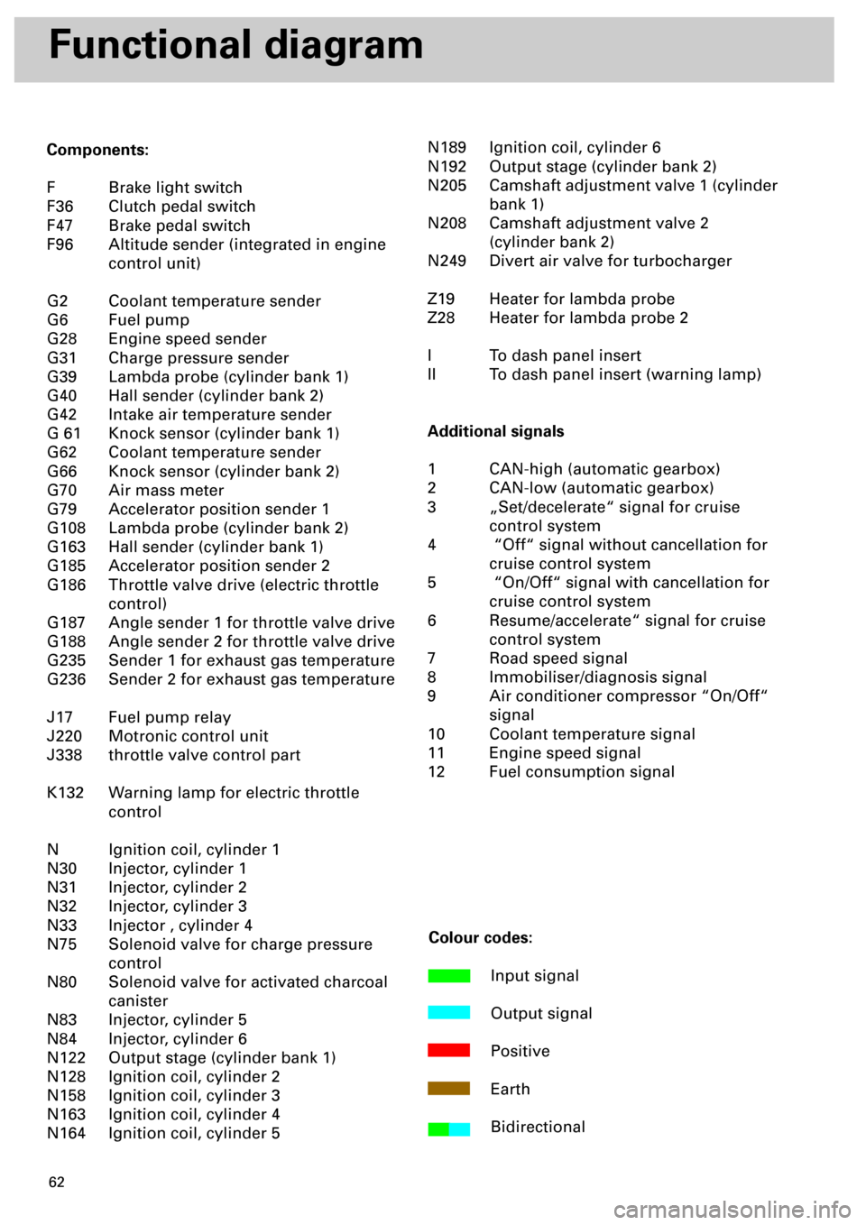
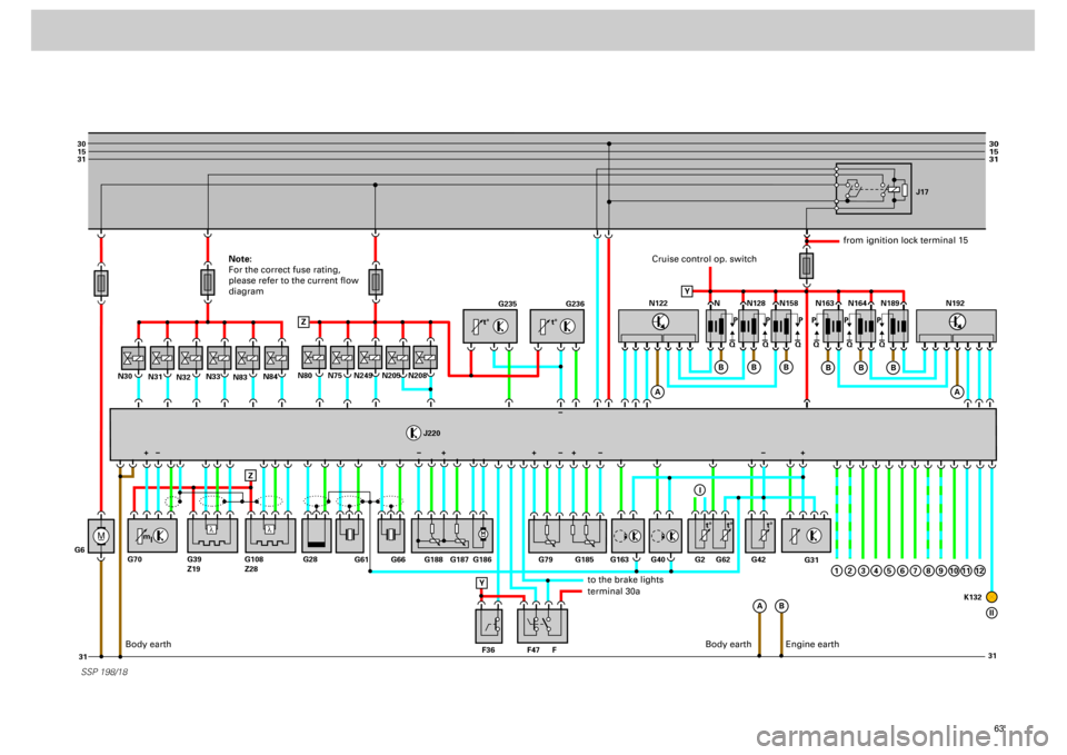
Functional diagram
Components:
F Brake light switch
F36 Clutch pedal switch
F47 Brake pedal switch
F96 Altitude sender (integrated in engine
control unit)
G2 Coolant temperature sender
G6 Fuel pump
G28 Engine speed sender
G31 Charge pressure sender
G39 Lambda probe (cylinder bank 1)
G40 Hall sender (cylinder bank 2)
G42 Intake air temperature sender
G 61 Knock sensor (cylinder bank 1)
G62 Coolant temperature sender
G66 Knock sensor (cylinder bank 2)
G70 Air mass meter
G79 Accelerator position sender 1
G108 Lambda probe (cylinder bank 2)
G163 Hall sender (cylinder bank 1)
G185 Accelerator position sender 2
G186 Throttle valve drive (electric throttle
control)
G187 Angle sender 1 for throttle valve drive
G188 Angle sender 2 for throttle valve drive
G235 Sender 1 for exhaust gas temperature
G236 Sender 2 for exhaust gas temperature
J17 Fuel pump relay
J220 Motronic control unit
J338 throttle valve control part
K132 Warning lamp for electric throttle
control
N Ignition coil, cylinder 1
N30 Injector, cylinder 1
N31 Injector, cylinder 2
N32 Injector, cylinder 3
N33 Injector , cylinder 4
N75 Solenoid valve for charge pressure
control
N80 Solenoid valve for activated charcoal
canister
N83 Injector, cylinder 5
N84 Injector, cylinder 6
N122 Output stage (cylinder bank 1)
N128 Ignition coil, cylinder 2
N158 Ignition coil, cylinder 3
N163 Ignition coil, cylinder 4
N164 Ignition coil, cylinder 5N189 Ignition coil, cylinder 6
N192 Output stage (cylinder bank 2)
N205 Camshaft adjustment valve 1 (cylinder
bank 1)
N208 Camshaft adjustment valve 2
(cylinder bank 2)
N249 Divert air valve for turbocharger
Z19 Heater for lambda probe
Z28 Heater for lambda probe 2
I To dash panel insert
II To dash panel insert (warning lamp)
Additional signals
1 CAN-high (automatic gearbox)
2 CAN-low (automatic gearbox)
3 „Set/decelerate“ signal for cruise
control system
4 “Off“ signal without cancellation for
cruise control system
5 “On/Off“ signal with cancellation for
cruise control system
6 Resume/accelerate“ signal for cruise
control system
7 Road speed signal
8 Immobiliser/diagnosis signal
9 Air conditioner compressor “On/Off“
signal
10 Coolant temperature signal
11 Engine speed signal
12 Fuel consumption signal
Colour codes:
Input signal
Output signal
Positive
Earth
Bidirectional
Page 62 of 72

63
M
30
15
31
31 31
30
15
31
_
G6N31
N32N33N80
J220
N83N84
N30
N75
N249
N205
N208
SSP 198/18
G235
G236
G31
N N128J17
N158 N163 N164 N189
Q PPPPPP
QQ QQQ
A
A
B Z
ZB
B
B
N122
A
B
B
B
1
N192
G61
G66 G188 G187 G186 G79
F47 F36 FG163 G40 G62G2 G42
K132 G185
G28 G70 G39
Z19G108
Z28
Y
+
Y
I
2
3
4
5
6
7
8
9
10
11
12
II
l
l
t° t°
m
lt° t° t°
+++ +
Cruise control op. switch
from ignition lock terminal 15
to the brake lightsterminal 30a
Body earth
Engine earth
Note:
For the correct fuse rating,
please refer to the current flow
diagram
Body earth