ignition AUDI S4 1998 B5 / 1.G Engine Manual
[x] Cancel search | Manufacturer: AUDI, Model Year: 1998, Model line: S4, Model: AUDI S4 1998 B5 / 1.GPages: 72, PDF Size: 3.25 MB
Page 20 of 72
21
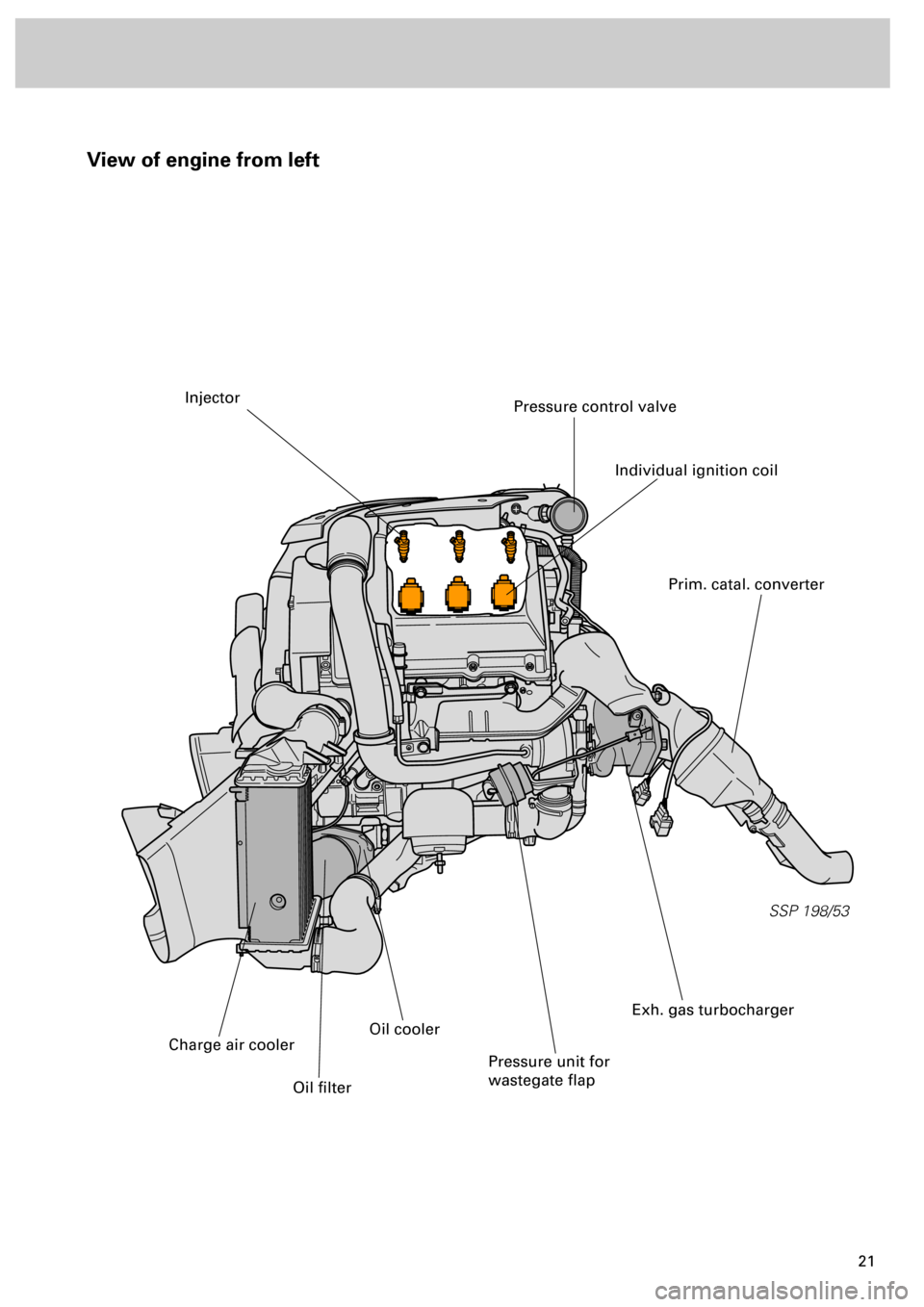
View of engine from left
SSP 198/53
Injector
Individual ignition coil
Pressure control valve
Prim. catal. converter
Exh. gas turbocharger
Pressure unit for
wastegate flap
Oil cooler
Oil filter
Charge air cooler
Page 30 of 72
31
Motronic ME 7.1
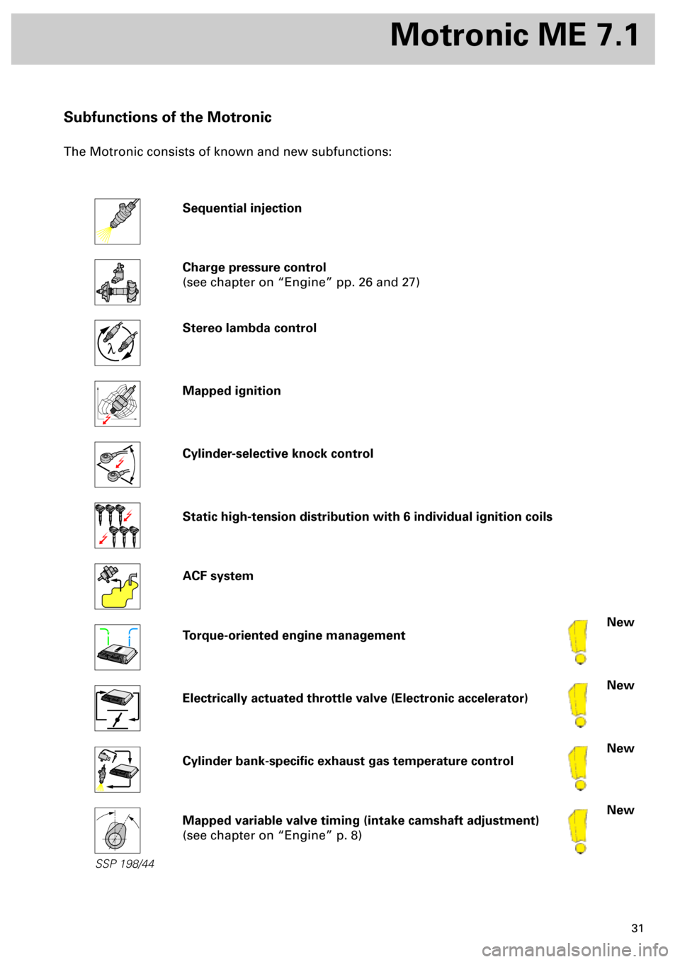
Subfunctions of the Motronic
The Motronic consists of known and new subfunctions:
Sequential injection
Charge pressure control
(see chapter on “Engine” pp. 26 and 27)
Stereo lambda control
Mapped ignition
Cylinder-selective knock control
Static high-tension distribution with 6 individual ignition coils
ACF system
Torque-oriented engine management
Electrically actuated throttle valve (Electronic accelerator)
Cylinder bank-specific exhaust gas temperature control
Mapped variable valve timing (intake camshaft adjustment)
(see chapter on “Engine” p. 8)
New
New
New
New
l
SSP 198/44
Page 31 of 72
32
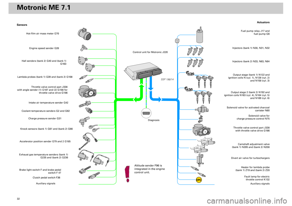
Actuators
Heater for lambda probe
(bank 1) Z19 and (bank 2) Z28
Divert air valve for turbochargers
Camshaft adjustment valve
(bank 1) N205 and (bank 2) N208
Throttle valve control part J338
with throttle valve drive G186
Solenoid valve for
charge pressure control N75
Solenoid valve for activated charcoal
canister N80
Output stage (bank 1) N122 and
ignition coils N (cyl. 1), N128 (cyl. 2)
and N158 (cyl. 3)Injectors (bank 1) N30, N31, N32
Fuel pump relay J17 and
fuel pump G6
Output stage 2 (bank 2) N192 and
ignition coils N163 (cyl. 4), N164 (cyl. 5)
and N189 (cyl. 6)
Fault lamp for electric
throttle control K132
Auxiliary signals
Sensors
Engine speed sender G28
Hall senders (bank 2) G40 and (bank 1)
G163
Lambda probes (bank 1) G39 and (bank 2) G108
Throttle valve control part J338
with angle sender (1) G187 and (2) G188 for
throttle valve drive G186
Intake air temperature sender G42
Coolant temperature senders G2 and G62
Charge pressure sender G31
Knock sensors (bank 1) G61 and (bank 2) G66Accelerator position sender G79 and 2 G185Exhaust gas temperature senders (bank 1)
G235 and (bank 2) G236Brake light switch F and brake pedal
switch F 47
Clutch pedal switch F36
Auxiliary signals
SSP 198/14
EPC
Injectors (bank 2) N33, N83, N84
Hot-film air mass meter G70
Control unit for Motronic J220
Altitude sender F96 is
integrated in the engine
control unit.
Diagnosis
Motronic ME 7.1
Page 32 of 72
33
SSP/198/15
Subsystems of the Motronic
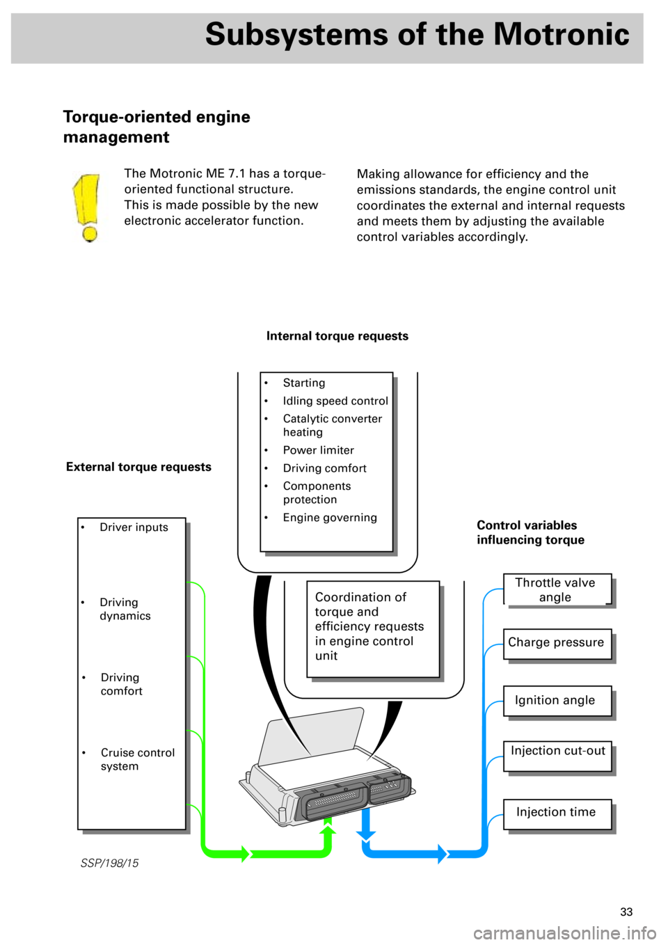
Making allowance for efficiency and the
emissions standards, the engine control unit
coordinates the external and internal requests
and meets them by adjusting the available
control variables accordingly.
Torque-oriented engine
management
The Motronic ME 7.1 has a torque-
oriented functional structure.
This is made possible by the new
electronic accelerator function.
Internal torque requests
External torque requests
• Starting
• Idling speed control
• Catalytic converter
heating
• Power limiter
• Driving comfort
• Components
protection
• Engine governing
• Driver inputs
Throttle valve
angle
Charge pressure
Ignition angle
Injection cut-out
Injection time
Control variables
influencing torque
• Driving
dynamics
• Driving
comfort
• Cruise control
system
Coordination of
torque and
efficiency requests
in engine control
unit
Page 33 of 72
34
Subsystems of the Motronic
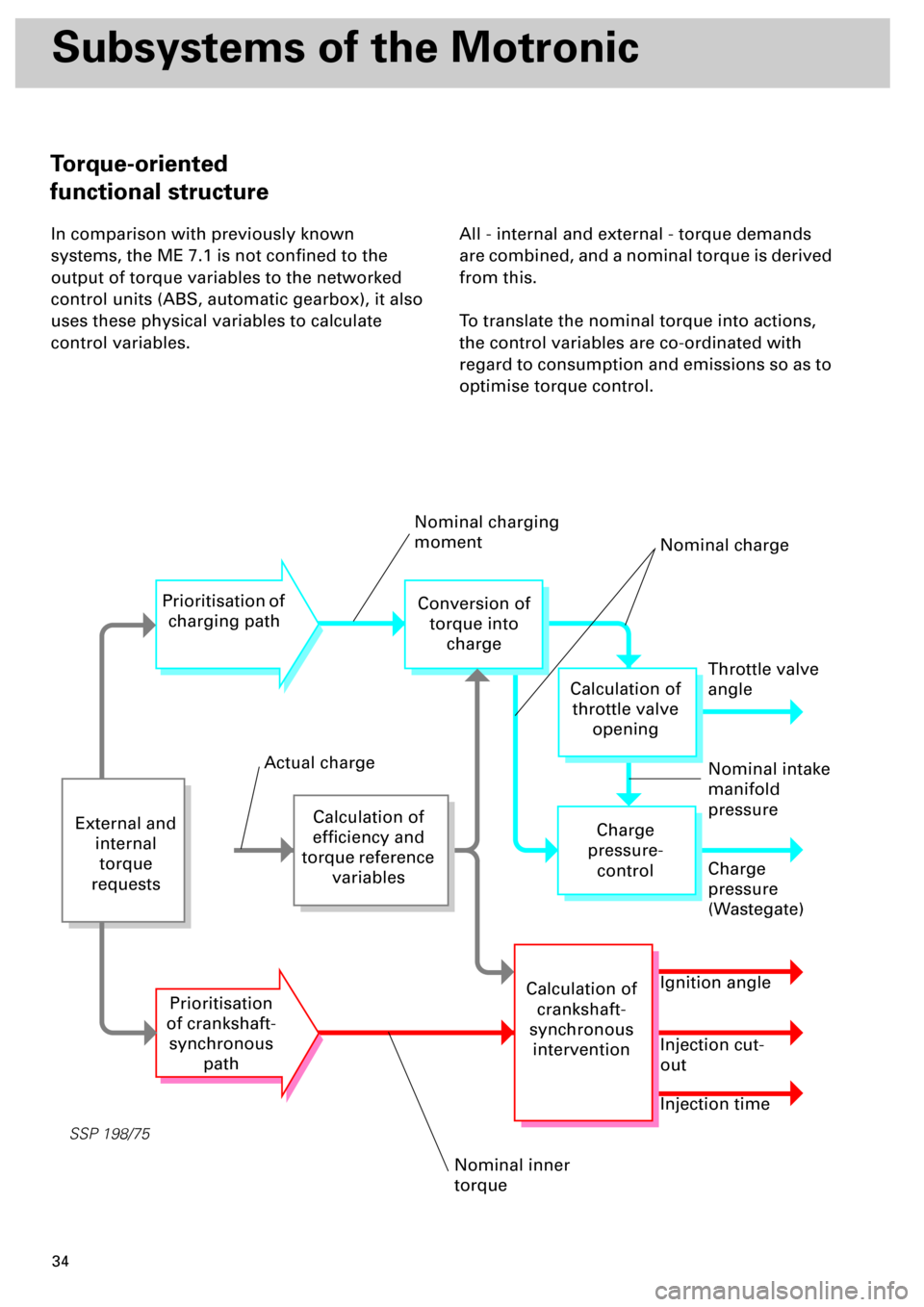
In comparison with previously known
systems, the ME 7.1 is not confined to the
output of torque variables to the networked
control units (ABS, automatic gearbox), it also
uses these physical variables to calculate
control variables.All - internal and external - torque demands
are combined, and a nominal torque is derived
from this.
To translate the nominal torque into actions,
the control variables are co-ordinated with
regard to consumption and emissions so as to
optimise torque control.
SSP 198/75
External and
internal
torque
requests
Calculation of
efficiency and
torque reference
variables
Prioritisation of
charging path
Prioritisation
of crankshaft-
synchronous
path
Conversion of
torque into
charge
Throttle valve
angle
Charge
pressure-
control
Calculation of
crankshaft-
synchronous
intervention
Calculation of
throttle valve
opening
Charge
pressure
(Wastegate)
Ignition angle
Injection cut-
out
Injection time
Nominal charging
moment
Nominal charge
Nominal intake
manifold
pressure
Nominal inner
torque
Actual charge
Torque-oriented
functional structure
Page 34 of 72
35
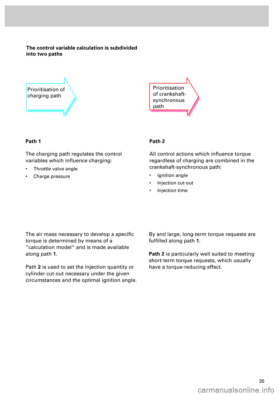
The control variable calculation is subdivided
into two paths
Path 1
The charging path regulates the control
variables which influence charging:
• Throttle valve angle
• Charge pressure
Path 2
All control actions which influence torque
regardless of charging are combined in the
crankshaft-synchronous path:
• Ignition angle
• Injection cut-out
• Injection time
The air mass necessary to develop a specific
torque is determined by means of a
“calculation model“ and is made available
along path
1
.
Path
2
is used to set the injection quantity or
cylinder cut-out necessary under the given
circumstances and the optimal ignition angle.
Prioritisation of
charging pathPrioritisation
of crankshaft-
synchronous
path
By and large, long-term torque requests are
fulfilled along path
1
.
Path 2
is particularly well suited to meeting
short-term torque requests, which usually
have a torque-reducing effect.
Page 41 of 72
42
Subsystems of the Motronic
To enable the exact angular position of the throttle valve to be identified, angle senders for
throttle valve drive G187 and G188 must be learnt .
By moving the throttle valve into predefined positions, the values of the angle senders are stored
in the control unit (calibrated) and checked for plausibility. The state of the mechanics (terminals,
weak springs) in the throttle valve control part is determined by evaluating the throttle valve’s
reaction speed.
... involves not only learning the throttle
valve position, but also a complete check of
the throttle valve control part
... can be performed using the following
three methods:
•
manually
- provided the ignition has been
switched on for at least 24 minutes without
operating the starter or accelerator.
•
automatically -
provided the need for adaption
is acknowledged.
•
specifically -
by initiating basic setting 04 in
measured value block 60 (refer to Workshop
Manual)
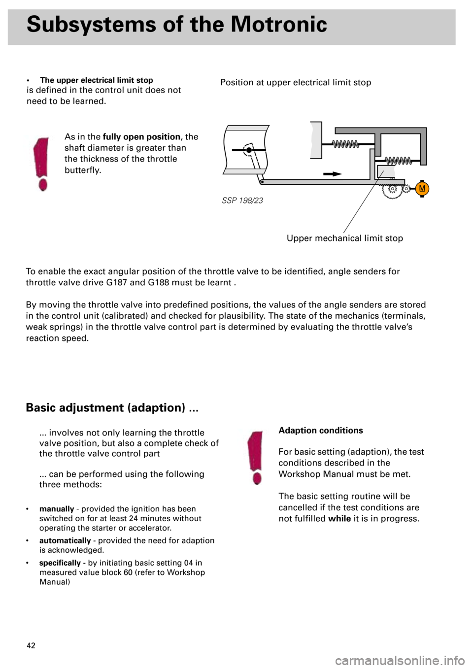
• The upper electrical limit stop
is defined in the control unit does not
need to be learned.
As in the
fully open position
, the
shaft diameter is greater than
the thickness of the throttle
butterfly.
SSP 198/23
Upper mechanical limit stop
Position at upper electrical limit stop
Basic adjustment (adaption) ...
Adaption conditions
For basic setting (adaption), the test
conditions described in the
Workshop Manual must be met.
The basic setting routine will be
cancelled if the test conditions are
not fulfilled
while
it is in progress.
Page 42 of 72
43
Emergency running program 1
If an angle sender for throttle valve drive fails
or an implausible signal is received:
• Torque-increasing requests on engine, e.g. CCS,
EBC (engine braking control) are suppressed.
• The fault lamp for electrical throttle control K132
comes on.
Prerequisite:
An intact angle sender and plausible
air mass flow. The air mass flow is
indicated by the air mass meter and
the charge pressure sender G31.
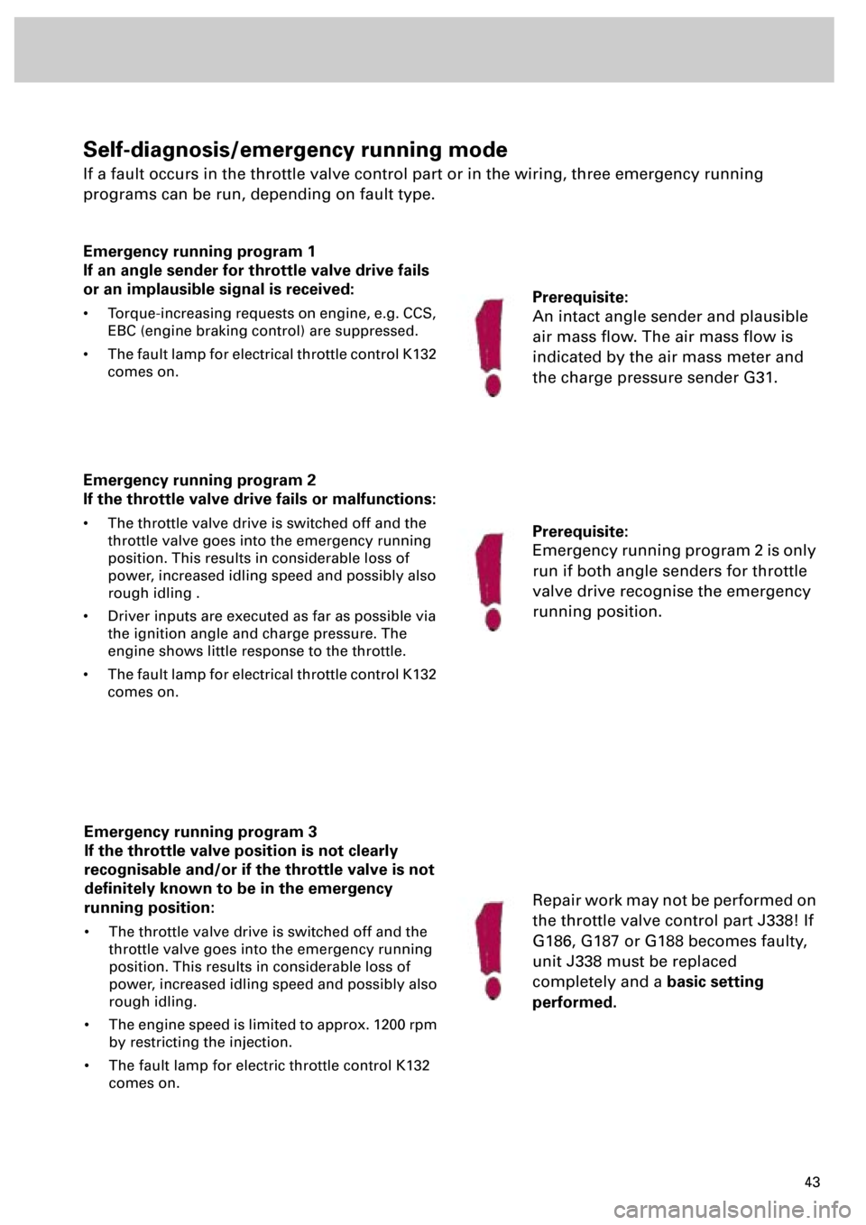
Self-diagnosis/emergency running mode
If a fault occurs in the throttle valve control part or in the wiring, three emergency running
programs can be run, depending on fault type.
Emergency running program 2
If the throttle valve drive fails or malfunctions:
• The throttle valve drive is switched off and the
throttle valve goes into the emergency running
position. This results in considerable loss of
power, increased idling speed and possibly also
rough idling .
• Driver inputs are executed as far as possible via
the ignition angle and charge pressure. The
engine shows little response to the throttle.
• The fault lamp for electrical throttle control K132
comes on.
Prerequisite:
Emergency running program 2 is only
run if both angle senders for throttle
valve drive recognise the emergency
running position.
Emergency running program 3
If the throttle valve position is not clearly
recognisable and/or if the throttle valve is not
definitely known to be in the emergency
running position:
• The throttle valve drive is switched off and the
throttle valve goes into the emergency running
position. This results in considerable loss of
power, increased idling speed and possibly also
rough idling.
• The engine speed is limited to approx. 1200 rpm
by restricting the injection.
• The fault lamp for electric throttle control K132
comes on.
Repair work may not be performed on
the throttle valve control part J338! If
G186, G187 or G188 becomes faulty,
unit J338 must be replaced
completely and a
basic setting
performed.
Page 43 of 72
44
Subsystems of the Motronic
120
180
°C 60
90
12
93
6
120
°C 60
12
16
120
100
80
50
30
10140
1234
5
6
7
160
180
200
220
260
Volt8
1/2
1/1
8
0
EPC
EPC
SSP 198/47
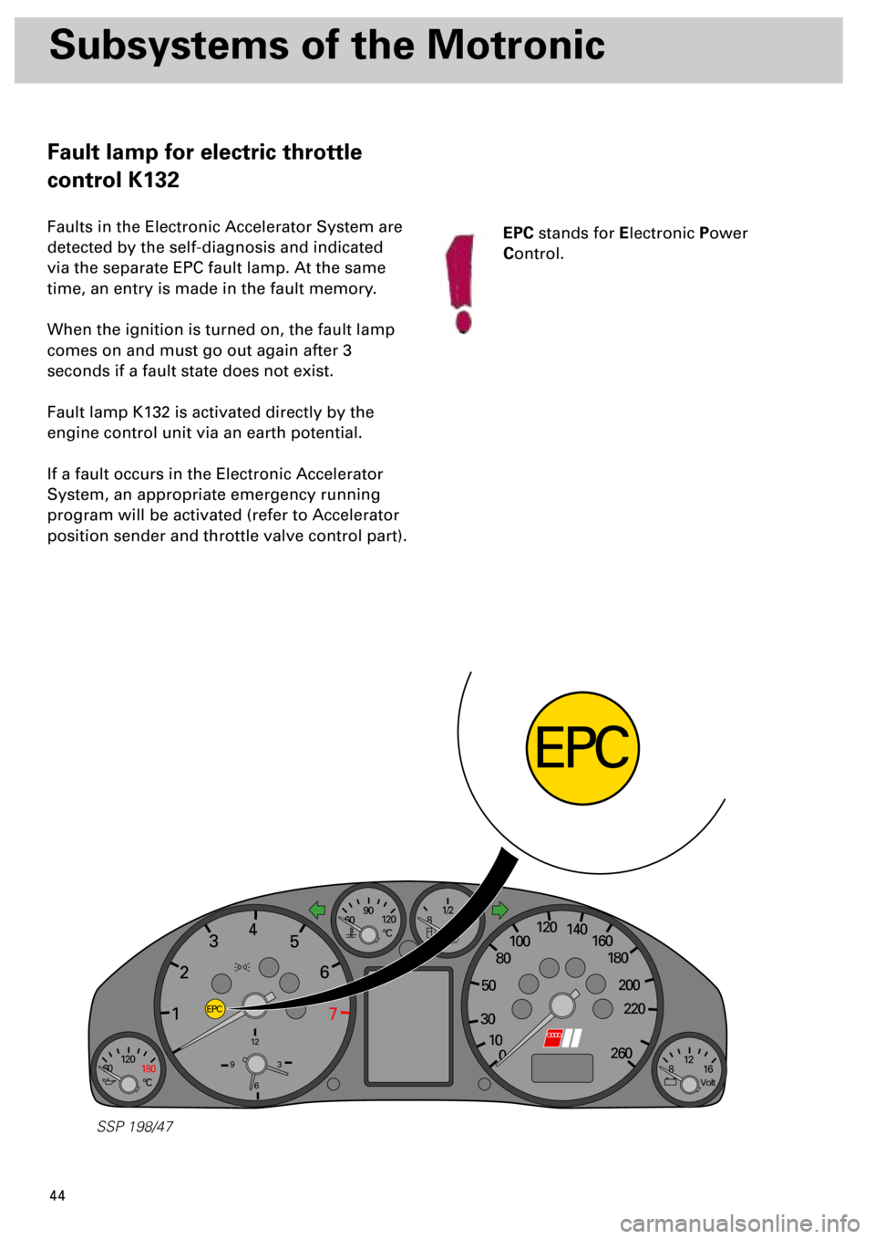
Fault lamp for electric throttle
control K132
Faults in the Electronic Accelerator System are
detected by the self-diagnosis and indicated
via the separate EPC fault lamp. At the same
time, an entry is made in the fault memory.
When the ignition is turned on, the fault lamp
comes on and must go out again after 3
seconds if a fault state does not exist.
Fault lamp K132 is activated directly by the
engine control unit via an earth potential.
If a fault occurs in the Electronic Accelerator
System, an appropriate emergency running
program will be activated (refer to Accelerator
position sender and throttle valve control part).
EPC
stands for
E
lectronic
P
ower
C
ontrol.
Page 52 of 72
53
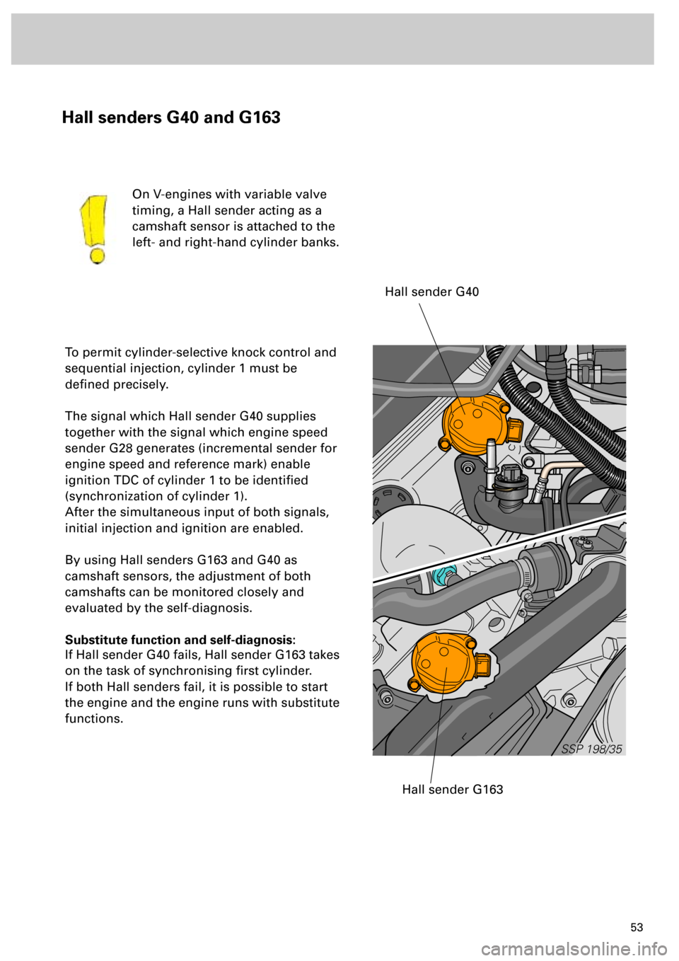
Hall senders G40 and G163
To permit cylinder-selective knock control and
sequential injection, cylinder 1 must be
defined precisely.
The signal which Hall sender G40 supplies
together with the signal which engine speed
sender G28 generates (incremental sender for
engine speed and reference mark) enable
ignition TDC of cylinder 1 to be identified
(synchronization of cylinder 1).
After the simultaneous input of both signals,
initial injection and ignition are enabled.
By using Hall senders G163 and G40 as
camshaft sensors, the adjustment of both
camshafts can be monitored closely and
evaluated by the self-diagnosis.
Substitute function and self-diagnosis:
If Hall sender G40 fails, Hall sender G163 takes
on the task of synchronising first cylinder.
If both Hall senders fail, it is possible to start
the engine and the engine runs with substitute
functions.On V-engines with variable valve
timing, a Hall sender acting as a
camshaft sensor is attached to the
left- and right-hand cylinder banks.
SSP 198/35
Hall sender G40
Hall sender G163