ESP AUDI S4 1998 B5 / 1.G Engine Manual
[x] Cancel search | Manufacturer: AUDI, Model Year: 1998, Model line: S4, Model: AUDI S4 1998 B5 / 1.GPages: 72, PDF Size: 3.25 MB
Page 2 of 72
2
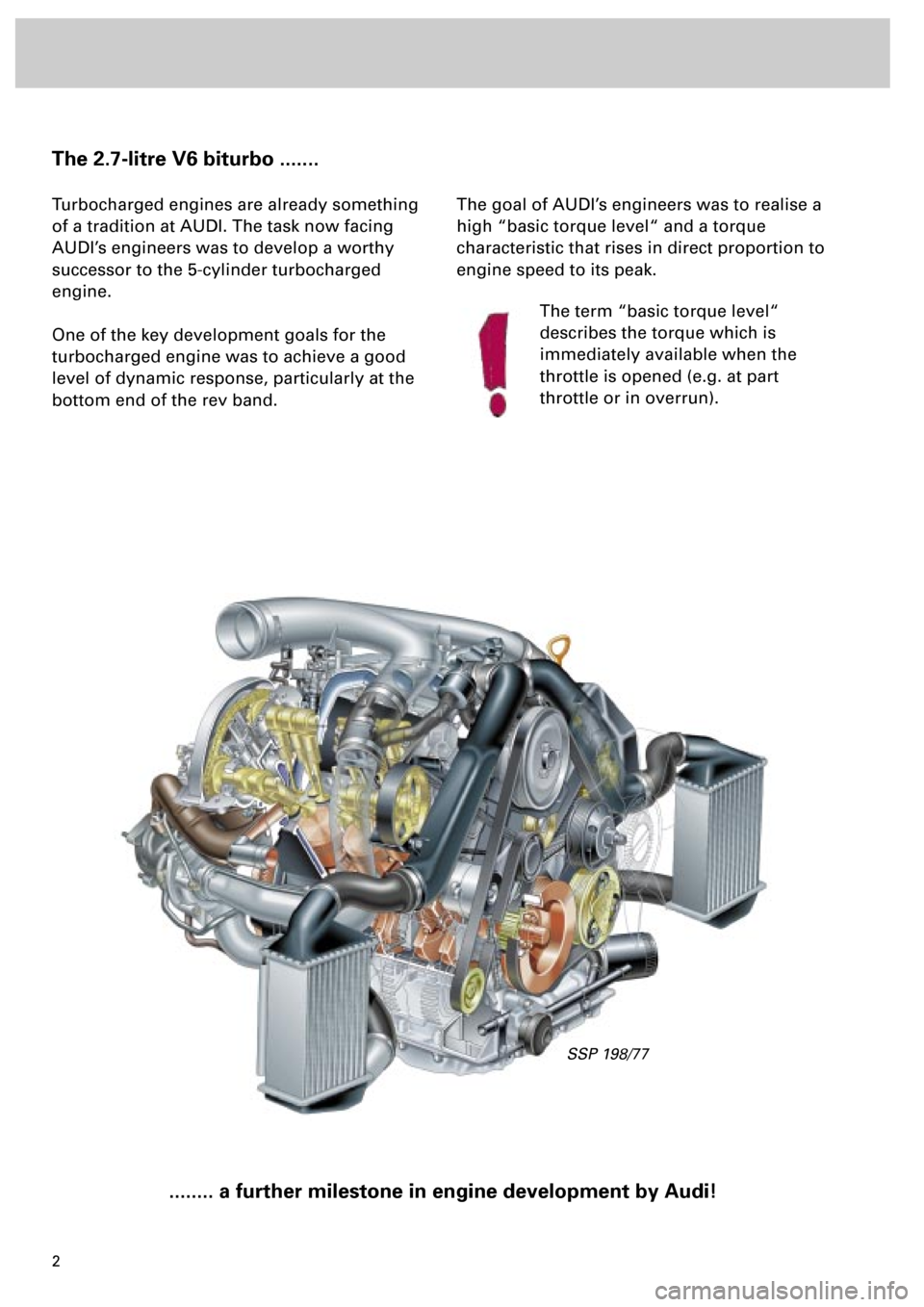
The 2.7-litre V6 biturbo .......
Turbocharged engines are already something
of a tradition at AUDI. The task now facing
AUDI’s engineers was to develop a worthy
successor to the 5-cylinder turbocharged
engine.
One of the key development goals for the
turbocharged engine was to achieve a good
level of dynamic response, particularly at the
bottom end of the rev band.
........ a further milestone in engine development by Audi!
The goal of AUDI’s engineers was to realise a
high “basic torque level“ and a torque
characteristic that rises in direct proportion to
engine speed to its peak.
The term “basic torque level“
describes the torque which is
immediately available when the
throttle is opened (e.g. at part
throttle or in overrun).
SSP 198/77
Page 14 of 72
1415
SSP 198/49
Engine
Engine lubrication
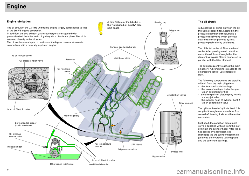
The oil circuit of the 2.7-litre V6 biturbo engine largely corresponds to that
of the 3rd V6 engine generation.
In addition, the two exhaust gas turbochargers are supplied with
pressurised oil from the main oil gallery via a distributor piece. The oil is
returned directly to the oil sump.
The oil cooler was adapted to withstand the higher thermal stresses in
comparison with a naturally aspirated engine.A new feature of the biturbo is
the “integrated oil supply“ (see
next page).
to oil filter/oil cooler
Spring-loaded slipper
(chain tensioner)
Main oil gallery
Oil retention valves
Bypass valve
Filter element
Bearing cap
Oil groove
Oil temperature
sender
Oil pressure switch
Restrictor
Oil retention
valve
distributor piece
The oil circuit
A duocentric oil pump draws in the oil
through a coarse filter. Located in the
pressure chamber of the pump is a
pressure relief valve which protects
downstream components against
pressure peaks during cold starts.
The oil is fed to the oil filter via the oil
cooler. After passing an oil retention
valve, the oil flows through the filter
element. A bypass filter is connected in
parallel with the filter element.
The oil subsequently reaches the main
oil gallery. A branch line is routed to the
oil pressure control valve (clean oil
side).
The following components are supplied
with oil from the main oil gallery:
- the four crankshaft bearings
- the two exhaust gas turbochargers
via an oil distributor line
- the three pairs of piston spray jets via
a spray jet valve
- the cylinder head of cylinder bank 1
via an oil retention valve
The cylinder head of cylinder bank 2 is
supplied through a separate bore from
crankshaft bearing 2 via an oil retention
valve also.
First of all, the camshaft adjustment
valve is supplied with oil from the inlet
drilling in the cylinder head. After the oil
has passed by a restrictor, it is
channeled via the cylinder head main
gallery to the hydraulic valve tappets
and the camshaft bearings.
Exhaust gas turbocharger
Bypass filter
Oil pressure relief valve
from oil filter/oil coolerOil pressure
control valveInduction filter
Oil pressure relief valve
from oil filter/oil cooler
to oil filter/oil cooler
Page 22 of 72
23
SSP 198/32
Charging
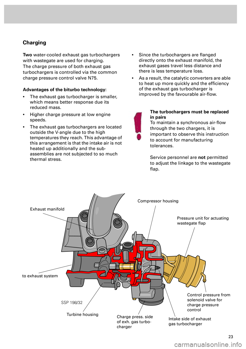
Two
water-cooled exhaust gas turbochargers
with wastegate are used for charging.
The charge pressure of both exhaust gas
turbochargers is controlled via the common
charge pressure control valve N75.
Advantages of the biturbo technology:
•
The exhaust gas turbocharger is smaller,
which means better response due its
reduced mass.
•
Higher charge pressure at low engine
speeds.
•
The exhaust gas turbochargers are located
outside the V-angle due to the high
temperatures they reach. This advantage of
this arrangement is that the intake air is not
heated up additionally and the sub-
assemblies are not subjected to so much
thermal stress.
•
Since the turbochargers are flanged
directly onto the exhaust manifold, the
exhaust gases travel less distance and
there is less temperature loss.
•
As a result, the catalytic converters are able
to heat up more quickly and the efficiency
of the exhaust gas turbocharger is
improved by the favourable air-flow.
Intake side of exhaust
gas turbocharger
Charge press. side
of exh. gas turbo-
charger
Exhaust manifold
to exhaust system
Pressure unit for actuating
wastegate flap
Control pressure from
solenoid valve for
charge pressure
control
The turbochargers must be replaced
in pairs
To maintain a synchronous air-flow
through the two chargers, it is
important to observe this instruction
to account for manufacturing
tolerances.
Service personnel are
not
permitted
to adjust the linkage to the wastegate
flap.
Turbine housing
Compressor housing
Page 37 of 72
38
Subsystems of the Motronic
SSP 198/12
Accelerator position senders G79
and G185
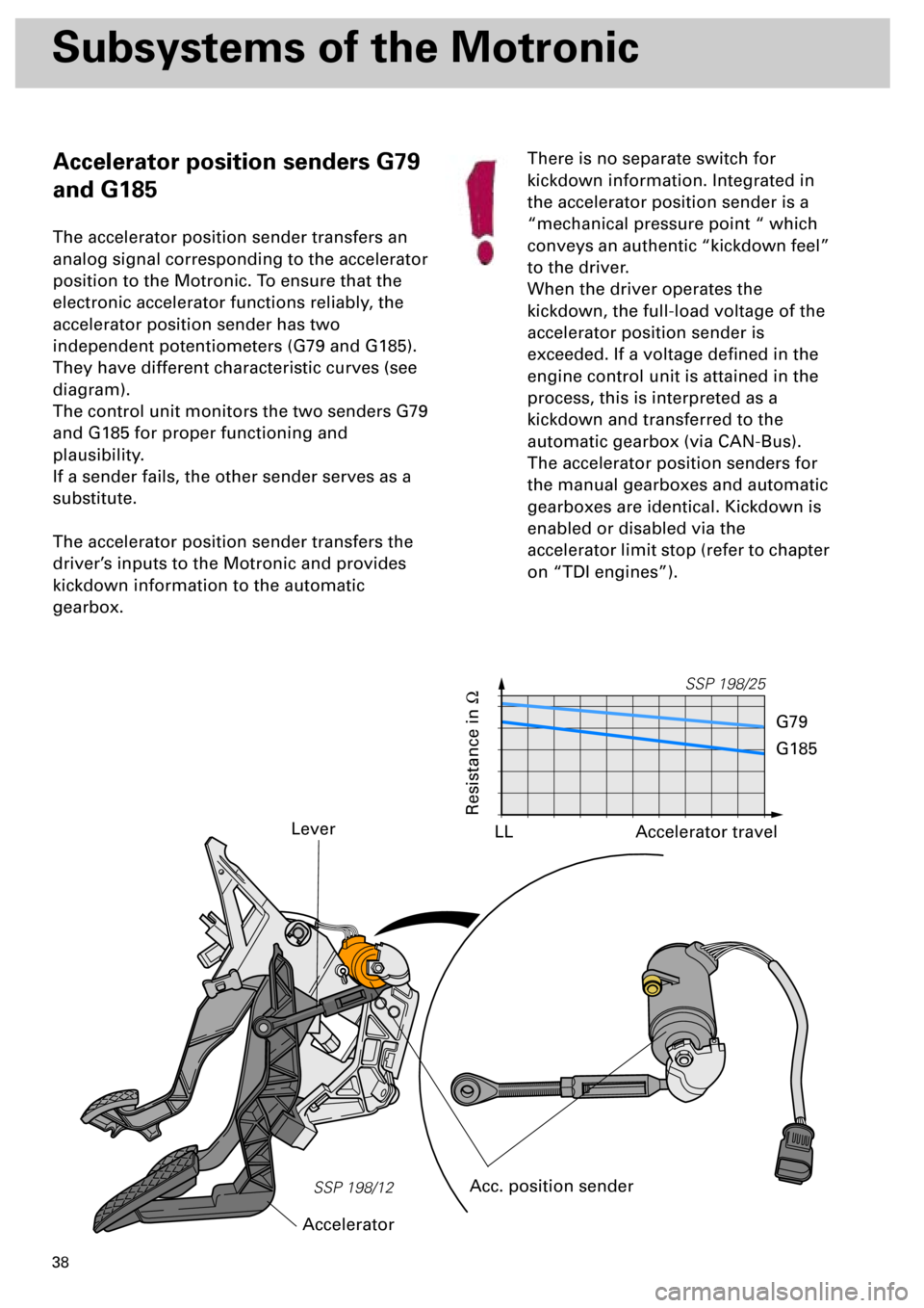
The accelerator position sender transfers an
analog signal corresponding to the accelerator
position to the Motronic. To ensure that the
electronic accelerator functions reliably, the
accelerator position sender has two
independent potentiometers (G79 and G185).
They have different characteristic curves (see
diagram).
The control unit monitors the two senders G79
and G185 for proper functioning and
plausibility.
If a sender fails, the other sender serves as a
substitute.
The accelerator position sender transfers the
driver’s inputs to the Motronic and provides
kickdown information to the automatic
gearbox.
Lever
Acc. position sender
AcceleratorThere is no separate switch for
kickdown information. Integrated in
the accelerator position sender is a
“mechanical pressure point “ which
conveys an authentic “kickdown feel”
to the driver.
When the driver operates the
kickdown, the full-load voltage of the
accelerator position sender is
exceeded. If a voltage defined in the
engine control unit is attained in the
process, this is interpreted as a
kickdown and transferred to the
automatic gearbox (via CAN-Bus).
The accelerator position senders for
the manual gearboxes and automatic
gearboxes are identical. Kickdown is
enabled or disabled via the
accelerator limit stop (refer to chapter
on “TDI engines”).
SSP 198/25
Resistance in
W
Accelerator travel
G79
G185
LL
Page 38 of 72
39
Self-diagnosis/emergency
running
If a fault occurs in the accelerator position
sender or the wiring, two emergency running
programs can be run depending on fault type.
Emergency running program 1
If an accelerator position sender fails:
• Accelerator position limited to a defined value.
• If a full load is predefined, the power output is
increased slowly.
• In the case of implausible signals between G79
and G185, the lower value is used.
Prerequisite:
The idling speed position must be learnt once
by the intact sender.
• The signal supplied by brake light switch for
brake pedal switch F47 indicates the idling
speed.
• Comfort functions (CCS) are prohibited.
• The fault lamp for electric throttle control K132
comes on.
Emergency running program 2
If both accelerator position senders fail, driver
input recognition is not possible:
• The engine only runs at idling speed.
• The fault lamp for electric throttle control K132
comes on.
At idling speed, the accelerator
position senders G79 and G185 are
not diagnosed.
If the plug of the accelerator position
sender drops off, no fault is stored in
the control unit.
The fault lamp for electric throttle
control K132 does not come on.
The engine runs at idling speed and
does not respond to the accelerator
pedal.
Safety function:
For safety reasons, the throttle valve
is closed as far as a defined angular
position when both the accelerator
pedal and the brake pedal are
depressed.
If the brake is pressed first followed
by the accelerator pedal, the driver
input (torque request) is executed.
Page 42 of 72

43
Emergency running program 1
If an angle sender for throttle valve drive fails
or an implausible signal is received:
• Torque-increasing requests on engine, e.g. CCS,
EBC (engine braking control) are suppressed.
• The fault lamp for electrical throttle control K132
comes on.
Prerequisite:
An intact angle sender and plausible
air mass flow. The air mass flow is
indicated by the air mass meter and
the charge pressure sender G31.
Self-diagnosis/emergency running mode
If a fault occurs in the throttle valve control part or in the wiring, three emergency running
programs can be run, depending on fault type.
Emergency running program 2
If the throttle valve drive fails or malfunctions:
• The throttle valve drive is switched off and the
throttle valve goes into the emergency running
position. This results in considerable loss of
power, increased idling speed and possibly also
rough idling .
• Driver inputs are executed as far as possible via
the ignition angle and charge pressure. The
engine shows little response to the throttle.
• The fault lamp for electrical throttle control K132
comes on.
Prerequisite:
Emergency running program 2 is only
run if both angle senders for throttle
valve drive recognise the emergency
running position.
Emergency running program 3
If the throttle valve position is not clearly
recognisable and/or if the throttle valve is not
definitely known to be in the emergency
running position:
• The throttle valve drive is switched off and the
throttle valve goes into the emergency running
position. This results in considerable loss of
power, increased idling speed and possibly also
rough idling.
• The engine speed is limited to approx. 1200 rpm
by restricting the injection.
• The fault lamp for electric throttle control K132
comes on.
Repair work may not be performed on
the throttle valve control part J338! If
G186, G187 or G188 becomes faulty,
unit J338 must be replaced
completely and a
basic setting
performed.
Page 51 of 72
52
Sensors
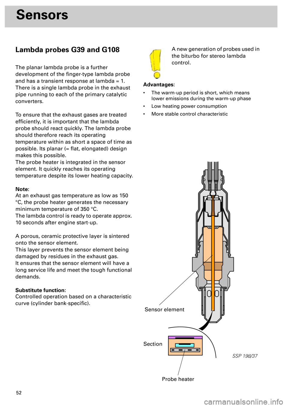
Lambda probes G39 and G108
The planar lambda probe is a further
development of the finger-type lambda probe
and has a transient response at lambda = 1.
There is a single lambda probe in the exhaust
pipe running to each of the primary catalytic
converters.
To ensure that the exhaust gases are treated
efficiently, it is important that the lambda
probe should react quickly. The lambda probe
should therefore reach its operating
temperature within as short a space of time as
possible. Its planar (= flat, elongated) design
makes this possible.
The probe heater is integrated in the sensor
element. It quickly reaches its operating
temperature despite its lower heating capacity.
Note:
At an exhaust gas temperature as low as 150
°C, the probe heater generates the necessary
minimum temperature of 350 °C.
The lambda control is ready to operate approx.
10 seconds after engine start-up.
A porous, ceramic protective layer is sintered
onto the sensor element.
This layer prevents the sensor element being
damaged by residues in the exhaust gas.
It ensures that the sensor element will have a
long service life and meet the tough functional
demands.
Substitute function:
Controlled operation based on a characteristic
curve (cylinder bank-specific).A new generation of probes used in
the biturbo for stereo lambda
control.
Advantages:
• The warm-up period is short, which means
lower emissions during the warm-up phase
• Low heating power consumption
• More stable control characteristic
SSP 198/37
Section
Probe heater
Sensor element
Page 60 of 72
61
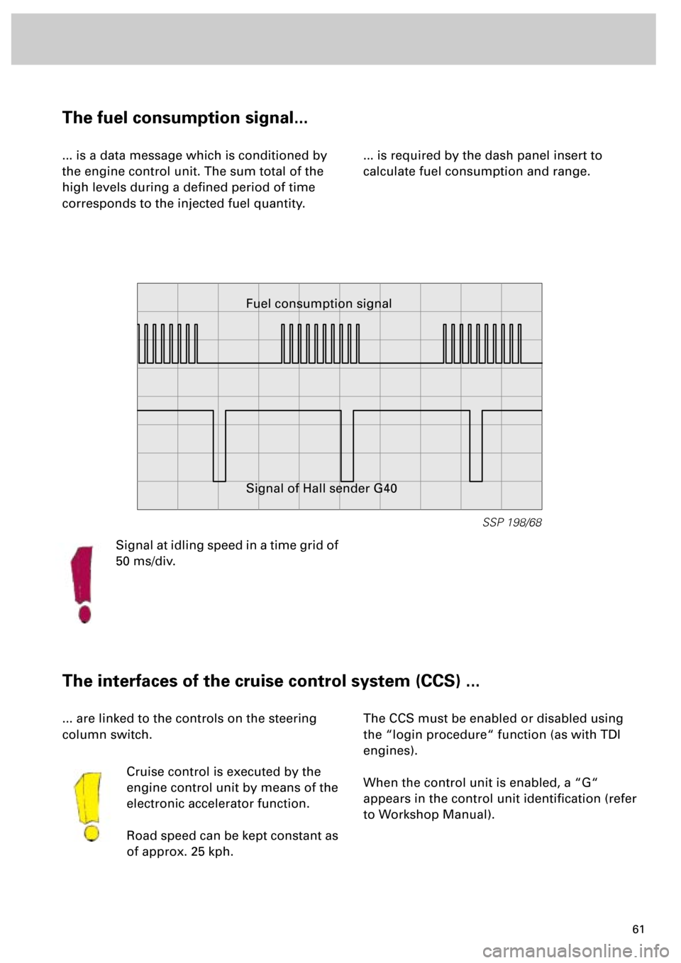
The fuel consumption signal...
... is a data message which is conditioned by
the engine control unit. The sum total of the
high levels during a defined period of time
corresponds to the injected fuel quantity.... is required by the dash panel insert to
calculate fuel consumption and range.
The interfaces of the cruise control system (CCS) ...
... are linked to the controls on the steering
column switch.
Cruise control is executed by the
engine control unit by means of the
electronic accelerator function.
Road speed can be kept constant as
of approx. 25 kph.The CCS must be enabled or disabled using
the “login procedure“ function (as with TDI
engines).
When the control unit is enabled, a “G“
appears in the control unit identification (refer
to Workshop Manual).
SSP 198/68
Fuel consumption signal
Signal of Hall sender G40
Signal at idling speed in a time grid of
50 ms/div.