lock AUDI S4 1998 B5 / 1.G Engine Manual
[x] Cancel search | Manufacturer: AUDI, Model Year: 1998, Model line: S4, Model: AUDI S4 1998 B5 / 1.GPages: 72, PDF Size: 3.25 MB
Page 8 of 72

8
Engine
The variable valve timing
The camshaft timing has been modified
compared to the 2.8-litre V6 engine to meet the
demands of turbocharging technology.
Variable valve timing with an adjustment angle
of 22° is used here for the first time in
turbocharged engines
.
Advantage:
•
A torque increase of approx. 10% is
achieved at the bottom and top ends of the
engine speed range.
•
Better emission levels and fuel
consumption figures.
The variable valve timing is activated by the
Motronic by means of camshaft adjustment
valves N205 and N208.The design and function of the
variable valve timing are already
described in Self-study Programmes
182 and 192.
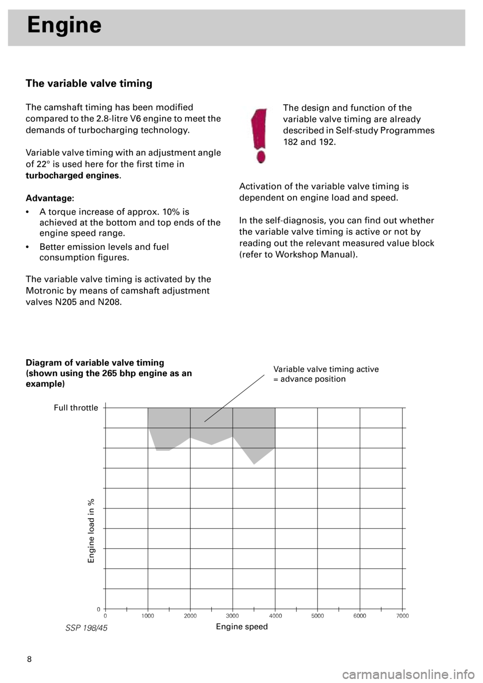
Activation of the variable valve timing is
dependent on engine load and speed.
In the self-diagnosis, you can find out whether
the variable valve timing is active or not by
reading out the relevant measured value block
(refer to Workshop Manual).
0
0 1000 2000 3000 4000 5000 6000 7000
SSP 198/45
Diagram of variable valve timing
(shown using the 265 bhp engine as an
example)
Engine speed
Engine load in %
Variable valve timing active
= advance position
Full throttle
Page 25 of 72

26
SSP 198/08
Engine
Charge pressure control
The air mass required to develop a specific
level of torque is determined by means of an air
mass calculation and produced by controlling
the charge pressure as required.
For safety reasons, the engine in the biturbo
regulates the charge pressure, and not the air
mass as is the case with the 1.8-litre 4-cylinder
turbocharged engine.
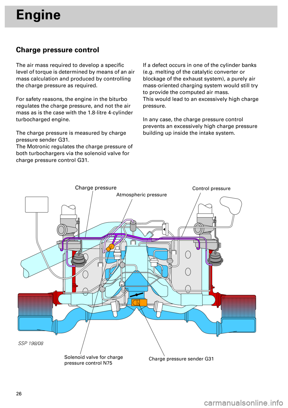
The charge pressure is measured by charge
pressure sender G31.
The Motronic regulates the charge pressure of
both turbochargers via the solenoid valve for
charge pressure control G31.
If a defect occurs in one of the cylinder banks
(e.g. melting of the catalytic converter or
blockage of the exhaust system), a purely air
mass-oriented charging system would still try
to provide the computed air mass.
This would lead to an excessively high charge
pressure.
In any case, the charge pressure control
prevents an excessively high charge pressure
building up inside the intake system.
Charge pressure sender G31
Atmospheric pressure
Solenoid valve for charge
pressure control N75
Charge pressure
Control pressure
Page 41 of 72

42
Subsystems of the Motronic
To enable the exact angular position of the throttle valve to be identified, angle senders for
throttle valve drive G187 and G188 must be learnt .
By moving the throttle valve into predefined positions, the values of the angle senders are stored
in the control unit (calibrated) and checked for plausibility. The state of the mechanics (terminals,
weak springs) in the throttle valve control part is determined by evaluating the throttle valve’s
reaction speed.
... involves not only learning the throttle
valve position, but also a complete check of
the throttle valve control part
... can be performed using the following
three methods:
•
manually
- provided the ignition has been
switched on for at least 24 minutes without
operating the starter or accelerator.
•
automatically -
provided the need for adaption
is acknowledged.
•
specifically -
by initiating basic setting 04 in
measured value block 60 (refer to Workshop
Manual)
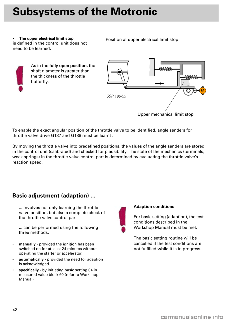
• The upper electrical limit stop
is defined in the control unit does not
need to be learned.
As in the
fully open position
, the
shaft diameter is greater than
the thickness of the throttle
butterfly.
SSP 198/23
Upper mechanical limit stop
Position at upper electrical limit stop
Basic adjustment (adaption) ...
Adaption conditions
For basic setting (adaption), the test
conditions described in the
Workshop Manual must be met.
The basic setting routine will be
cancelled if the test conditions are
not fulfilled
while
it is in progress.
Page 62 of 72

63
M
30
15
31
31 31
30
15
31
_
G6N31
N32N33N80
J220
N83N84
N30
N75
N249
N205
N208
SSP 198/18
G235
G236
G31
N N128J17
N158 N163 N164 N189
Q PPPPPP
QQ QQQ
A
A
B Z
ZB
B
B
N122
A
B
B
B
1
N192
G61
G66 G188 G187 G186 G79
F47 F36 FG163 G40 G62G2 G42
K132 G185
G28 G70 G39
Z19G108
Z28
Y
+
Y
I
2
3
4
5
6
7
8
9
10
11
12
II
l
l
t° t°
m
lt° t° t°
+++ +
Cruise control op. switch
from ignition lock terminal 15
to the brake lightsterminal 30a
Body earth
Engine earth
Note:
For the correct fuse rating,
please refer to the current flow
diagram
Body earth