cruise control AUDI S4 1998 B5 / 1.G Engine Manual
[x] Cancel search | Manufacturer: AUDI, Model Year: 1998, Model line: S4, Model: AUDI S4 1998 B5 / 1.GPages: 72, PDF Size: 3.25 MB
Page 32 of 72
33
SSP/198/15
Subsystems of the Motronic
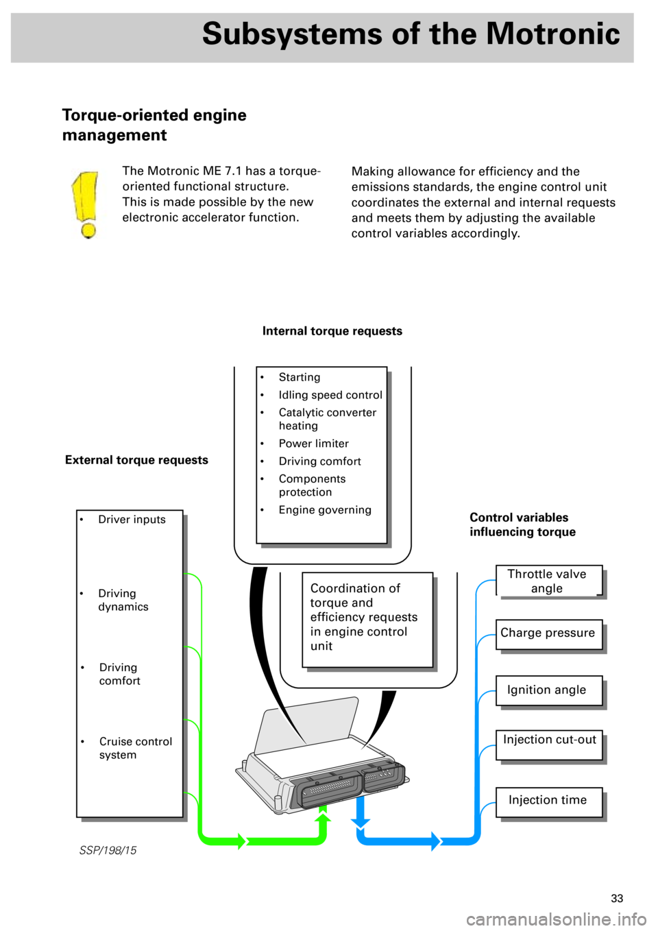
Making allowance for efficiency and the
emissions standards, the engine control unit
coordinates the external and internal requests
and meets them by adjusting the available
control variables accordingly.
Torque-oriented engine
management
The Motronic ME 7.1 has a torque-
oriented functional structure.
This is made possible by the new
electronic accelerator function.
Internal torque requests
External torque requests
• Starting
• Idling speed control
• Catalytic converter
heating
• Power limiter
• Driving comfort
• Components
protection
• Engine governing
• Driver inputs
Throttle valve
angle
Charge pressure
Ignition angle
Injection cut-out
Injection time
Control variables
influencing torque
• Driving
dynamics
• Driving
comfort
• Cruise control
system
Coordination of
torque and
efficiency requests
in engine control
unit
Page 36 of 72
37
The electronic accelerator controls the engine
output electronically and, over and above
intake-air control, offers the advantage that
functions such as idling speed control, cruise
control or engine governing can be executed
easily and comfortably.
.
The throttle valve can be opened regardless of
the accelerator position, and this serves to
reduce throttle losses.
The ideal combination of throttle valve cross-
section and charge pressure produce the
necessary torque.
In this way, the throttle valve can be opened
fully while the accelerator pedal has not been
fully depressed.With electronic accelerator, much improved
emissions and higher fuel economy are
achieved in specific load states.
Over and above this, any accelerator
characteristic can be programmed, e.g.
gradual acceleration when driving at low
speed.
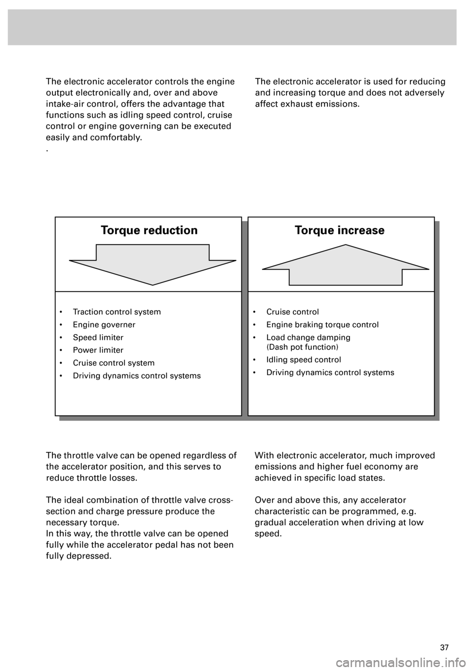
The electronic accelerator is used for reducing
and increasing torque and does not adversely
affect exhaust emissions.
• Traction control system
• Engine governer
• Speed limiter
• Power limiter
• Cruise control system
• Driving dynamics control systems
Torque reduction
Torque increase
• Cruise control
• Engine braking torque control
• Load change damping
(Dash pot function)
• Idling speed control
• Driving dynamics control systems
Page 55 of 72
56
Sensors
Brake light switch F and brake
pedal switch F47The information “brake operated“ is required
for the following functions:
• Function of cruise control system
• Safety interrogation of electronic accelerator
function (idling speed recognition during
emergency running mode of accelerator
position sender)
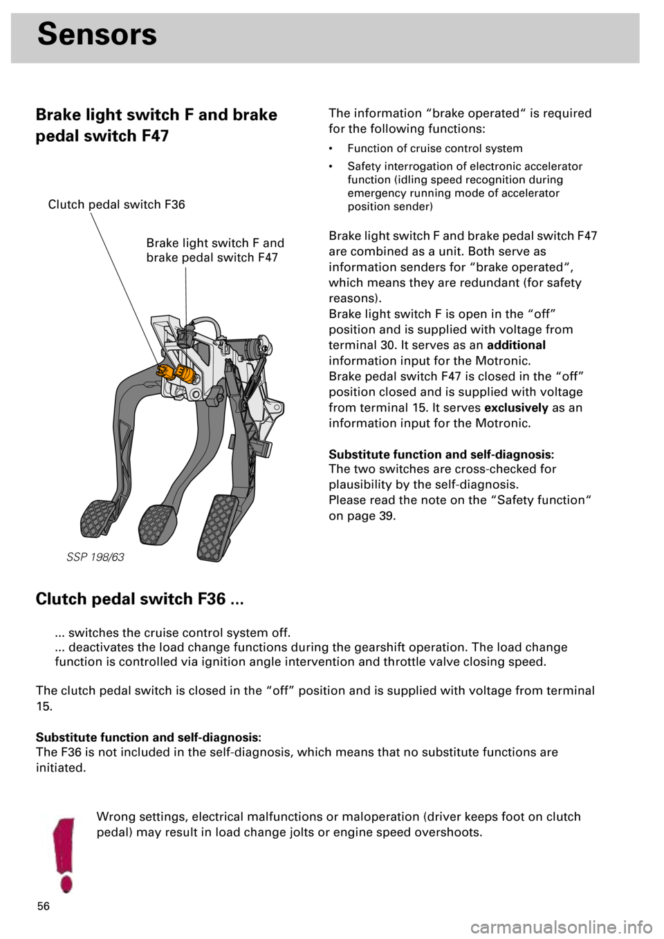
Brake light switch F and brake pedal switch F47
are combined as a unit. Both serve as
information senders for “brake operated“,
which means they are redundant (for safety
reasons).
Brake light switch F is open in the “off”
position and is supplied with voltage from
terminal 30. It serves as an additional
information input for the Motronic.
Brake pedal switch F47 is closed in the “off”
position closed and is supplied with voltage
from terminal 15. It serves exclusively as an
information input for the Motronic.
Substitute function and self-diagnosis:
The two switches are cross-checked for
plausibility by the self-diagnosis.
Please read the note on the “Safety function“
on page 39.
Clutch pedal switch F36 ...
Wrong settings, electrical malfunctions or maloperation (driver keeps foot on clutch
pedal) may result in load change jolts or engine speed overshoots.
... switches the cruise control system off.
... deactivates the load change functions during the gearshift operation. The load change
function is controlled via ignition angle intervention and throttle valve closing speed.
The clutch pedal switch is closed in the “off” position and is supplied with voltage from terminal
15.
Substitute function and self-diagnosis:
The F36 is not included in the self-diagnosis, which means that no substitute functions are
initiated.
SSP 198/63
Brake light switch F and
brake pedal switch F47
Clutch pedal switch F36
Page 56 of 72
57
Additional signals/interfaces
Additional signals/interfaces to
Motronic ME 7.1
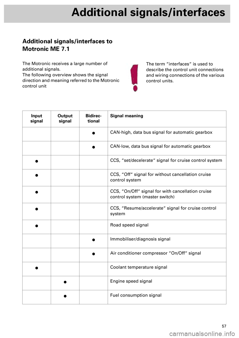
The Motronic receives a large number of
additional signals.
The following overview shows the signal
direction and meaning referred to the Motronic
control unit
Input
signalOutput
signalBidirec-
tionalSignal meaning
·CAN-high, data bus signal for automatic gearbox
·CAN-low, data bus signal for automatic gearbox
·CCS, “set/decelerate“ signal for cruise control system
·CCS, “Off“ signal for without cancellation cruise
control system
·CCS, “On/Off“ signal for with cancellation cruise
control system (master switch)
·CCS, “Resume/accelerate“ signal for cruise control
system
·Road speed signal
·Immobiliser/diagnosis signal
·Air conditioner compressor “On/Off“ signal
·Coolant temperature signal
·Engine speed signal
·Fuel consumption signal
The term “interfaces“ is used to
describe the control unit connections
and wiring connections of the various
control units.
Page 57 of 72
58
Additional signals/interfaces
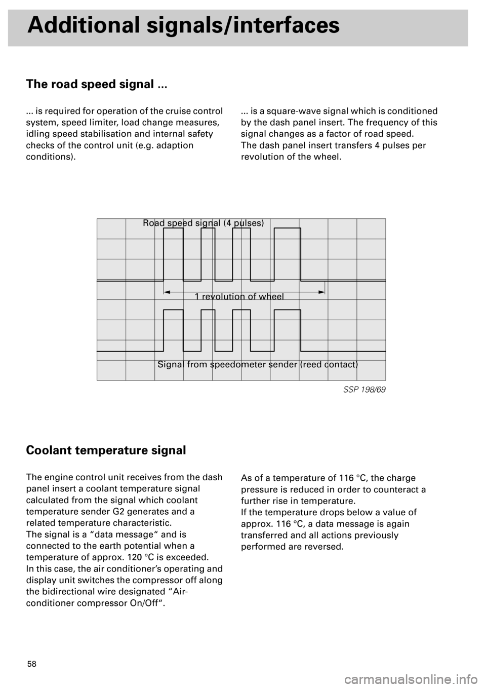
The road speed signal ...
... is required for operation of the cruise control
system, speed limiter, load change measures,
idling speed stabilisation and internal safety
checks of the control unit (e.g. adaption
conditions).... is a square-wave signal which is conditioned
by the dash panel insert. The frequency of this
signal changes as a factor of road speed.
The dash panel insert transfers 4 pulses per
revolution of the wheel.
Coolant temperature signal
The engine control unit receives from the dash
panel insert a coolant temperature signal
calculated from the signal which coolant
temperature sender G2 generates and a
related temperature characteristic.
The signal is a “data message“ and is
connected to the earth potential when a
temperature of approx. 120 °C is exceeded.
In this case, the air conditioner’s operating and
display unit switches the compressor off along
the bidirectional wire designated “Air-
conditioner compressor On/Off“.As of a temperature of 116 °C, the charge
pressure is reduced in order to counteract a
further rise in temperature.
If the temperature drops below a value of
approx. 116 °C, a data message is again
transferred and all actions previously
performed are reversed.
SSP 198/69
1 revolution of wheel Road speed signal (4 pulses)
Signal from speedometer sender (reed contact)
Page 60 of 72
61
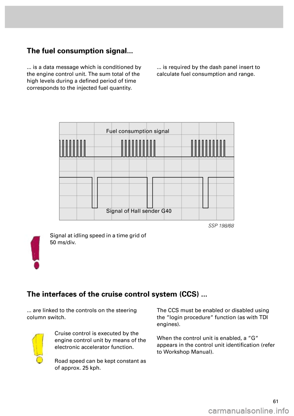
The fuel consumption signal...
... is a data message which is conditioned by
the engine control unit. The sum total of the
high levels during a defined period of time
corresponds to the injected fuel quantity.... is required by the dash panel insert to
calculate fuel consumption and range.
The interfaces of the cruise control system (CCS) ...
... are linked to the controls on the steering
column switch.
Cruise control is executed by the
engine control unit by means of the
electronic accelerator function.
Road speed can be kept constant as
of approx. 25 kph.The CCS must be enabled or disabled using
the “login procedure“ function (as with TDI
engines).
When the control unit is enabled, a “G“
appears in the control unit identification (refer
to Workshop Manual).
SSP 198/68
Fuel consumption signal
Signal of Hall sender G40
Signal at idling speed in a time grid of
50 ms/div.
Page 61 of 72
62
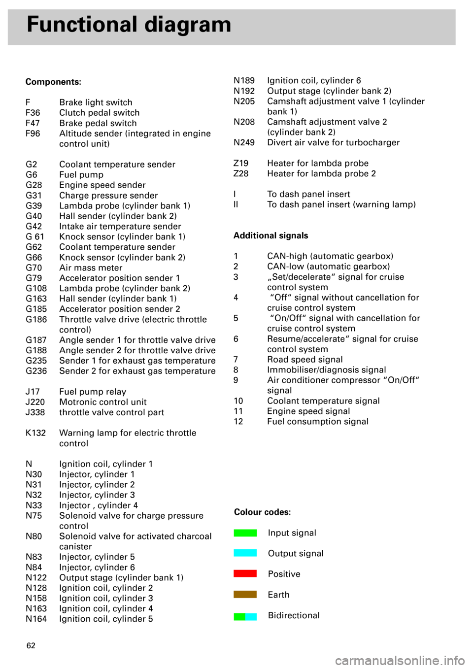
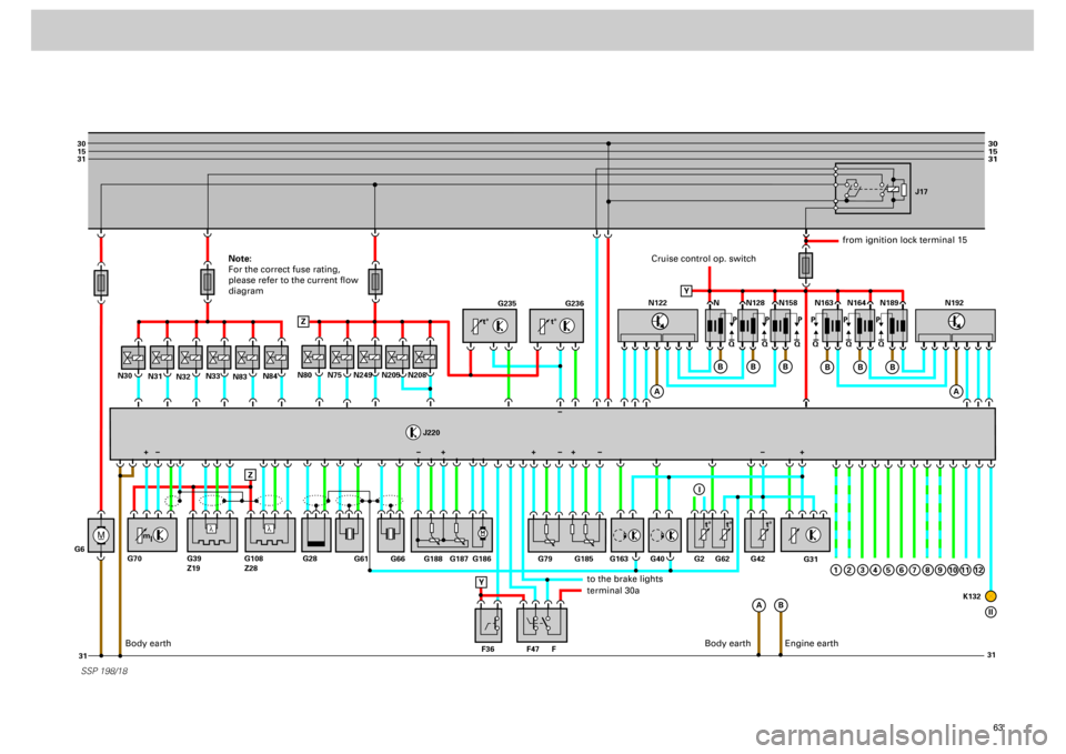
Functional diagram
Components:
F Brake light switch
F36 Clutch pedal switch
F47 Brake pedal switch
F96 Altitude sender (integrated in engine
control unit)
G2 Coolant temperature sender
G6 Fuel pump
G28 Engine speed sender
G31 Charge pressure sender
G39 Lambda probe (cylinder bank 1)
G40 Hall sender (cylinder bank 2)
G42 Intake air temperature sender
G 61 Knock sensor (cylinder bank 1)
G62 Coolant temperature sender
G66 Knock sensor (cylinder bank 2)
G70 Air mass meter
G79 Accelerator position sender 1
G108 Lambda probe (cylinder bank 2)
G163 Hall sender (cylinder bank 1)
G185 Accelerator position sender 2
G186 Throttle valve drive (electric throttle
control)
G187 Angle sender 1 for throttle valve drive
G188 Angle sender 2 for throttle valve drive
G235 Sender 1 for exhaust gas temperature
G236 Sender 2 for exhaust gas temperature
J17 Fuel pump relay
J220 Motronic control unit
J338 throttle valve control part
K132 Warning lamp for electric throttle
control
N Ignition coil, cylinder 1
N30 Injector, cylinder 1
N31 Injector, cylinder 2
N32 Injector, cylinder 3
N33 Injector , cylinder 4
N75 Solenoid valve for charge pressure
control
N80 Solenoid valve for activated charcoal
canister
N83 Injector, cylinder 5
N84 Injector, cylinder 6
N122 Output stage (cylinder bank 1)
N128 Ignition coil, cylinder 2
N158 Ignition coil, cylinder 3
N163 Ignition coil, cylinder 4
N164 Ignition coil, cylinder 5N189 Ignition coil, cylinder 6
N192 Output stage (cylinder bank 2)
N205 Camshaft adjustment valve 1 (cylinder
bank 1)
N208 Camshaft adjustment valve 2
(cylinder bank 2)
N249 Divert air valve for turbocharger
Z19 Heater for lambda probe
Z28 Heater for lambda probe 2
I To dash panel insert
II To dash panel insert (warning lamp)
Additional signals
1 CAN-high (automatic gearbox)
2 CAN-low (automatic gearbox)
3 „Set/decelerate“ signal for cruise
control system
4 “Off“ signal without cancellation for
cruise control system
5 “On/Off“ signal with cancellation for
cruise control system
6 Resume/accelerate“ signal for cruise
control system
7 Road speed signal
8 Immobiliser/diagnosis signal
9 Air conditioner compressor “On/Off“
signal
10 Coolant temperature signal
11 Engine speed signal
12 Fuel consumption signal
Colour codes:
Input signal
Output signal
Positive
Earth
Bidirectional
Page 62 of 72
63
M
30
15
31
31 31
30
15
31
_
G6N31
N32N33N80
J220
N83N84
N30
N75
N249
N205
N208
SSP 198/18
G235
G236
G31
N N128J17
N158 N163 N164 N189
Q PPPPPP
QQ QQQ
A
A
B Z
ZB
B
B
N122
A
B
B
B
1
N192
G61
G66 G188 G187 G186 G79
F47 F36 FG163 G40 G62G2 G42
K132 G185
G28 G70 G39
Z19G108
Z28
Y
+
Y
I
2
3
4
5
6
7
8
9
10
11
12
II
l
l
t° t°
m
lt° t° t°
+++ +
Cruise control op. switch
from ignition lock terminal 15
to the brake lightsterminal 30a
Body earth
Engine earth
Note:
For the correct fuse rating,
please refer to the current flow
diagram
Body earth