diagram AUDI S4 1998 B5 / 1.G Engine Manual
[x] Cancel search | Manufacturer: AUDI, Model Year: 1998, Model line: S4, Model: AUDI S4 1998 B5 / 1.GPages: 72, PDF Size: 3.25 MB
Page 3 of 72
3
This Self-study Programme provides you with information
regarding design and function.
The Self-study Programme is not a Workshop Manual!
Please refer to the Service Literature for all the relevant
maintenance and repair instructions.
Page
Engine .........................................................
Technical data, crankshaft, cylinder head,
camshaft timing, cooling circuit, engine
lubrication, overview of components, air ducting,
charging, exhaust system, pneumatically
controlled systems, charge pressure control, air
divert control in overrun, ACF system, crankcase
breather
4
Motronic ME 7.1 ..........................................
Subfunctions, system overview
31
Subsystems of the Motronic .....................
Torque-oriented engine management, torque-
oriented functional structure, Electronic throttle,
exhaust gas temperature control
33
Sensors .......................................................
Additional sensors of the Motronic
49
Auxiliary signals/interfaces ...................... 57
Functional diagram ..................................... 62
Self-diagnosis .............................................
Vehicle diagnosis, test and information system
VAS 5051, test box V.A.G 1598/31
64
Transmission ..............................................
Self-adjusting clutch, gearbox
66
Contents
Important!/Note!
New!
Page 8 of 72
8
Engine
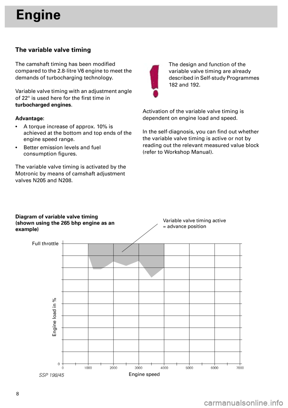
The variable valve timing
The camshaft timing has been modified
compared to the 2.8-litre V6 engine to meet the
demands of turbocharging technology.
Variable valve timing with an adjustment angle
of 22° is used here for the first time in
turbocharged engines
.
Advantage:
•
A torque increase of approx. 10% is
achieved at the bottom and top ends of the
engine speed range.
•
Better emission levels and fuel
consumption figures.
The variable valve timing is activated by the
Motronic by means of camshaft adjustment
valves N205 and N208.The design and function of the
variable valve timing are already
described in Self-study Programmes
182 and 192.
Activation of the variable valve timing is
dependent on engine load and speed.
In the self-diagnosis, you can find out whether
the variable valve timing is active or not by
reading out the relevant measured value block
(refer to Workshop Manual).
0
0 1000 2000 3000 4000 5000 6000 7000
SSP 198/45
Diagram of variable valve timing
(shown using the 265 bhp engine as an
example)
Engine speed
Engine load in %
Variable valve timing active
= advance position
Full throttle
Page 11 of 72
11
Fan control
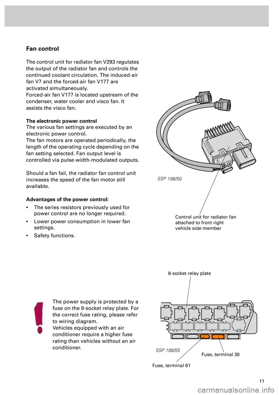
The control unit for radiator fan V293 regulates
the output of the radiator fan and controls the
continued coolant circulation. The induced-air
fan V7 and the forced-air fan V177 are
activated simultaneously.
Forced-air fan V177 is located upstream of the
condenser, water cooler and visco fan. It
assists the visco fan.
The electronic power control
The various fan settings are executed by an
electronic power control.
The fan motors are operated periodically, the
length of the operating cycle depending on the
fan setting selected. Fan output level is
controlled via pulse-width-modulated outputs.
Should a fan fail, the radiator fan control unit
increases the speed of the fan motor still
available.
Advantages of the power control:
•
The series resistors previously used for
power control are no longer required.
•
Lower power consumption in lower fan
settings.
•
Safety functions.
The power supply is protected by a
fuse on the 8-socket relay plate. For
the correct fuse rating, please refer
to wiring diagram.
Vehicles equipped with an air
conditioner require a higher fuse
rating than vehicles without an air
conditioner.
SSP 198/50
8-socket relay plate
SSP 198/55
Control unit for radiator fan
attached to front right
vehicle side member
Fuse, terminal 30
Fuse, terminal 61
Page 37 of 72
38
Subsystems of the Motronic
SSP 198/12
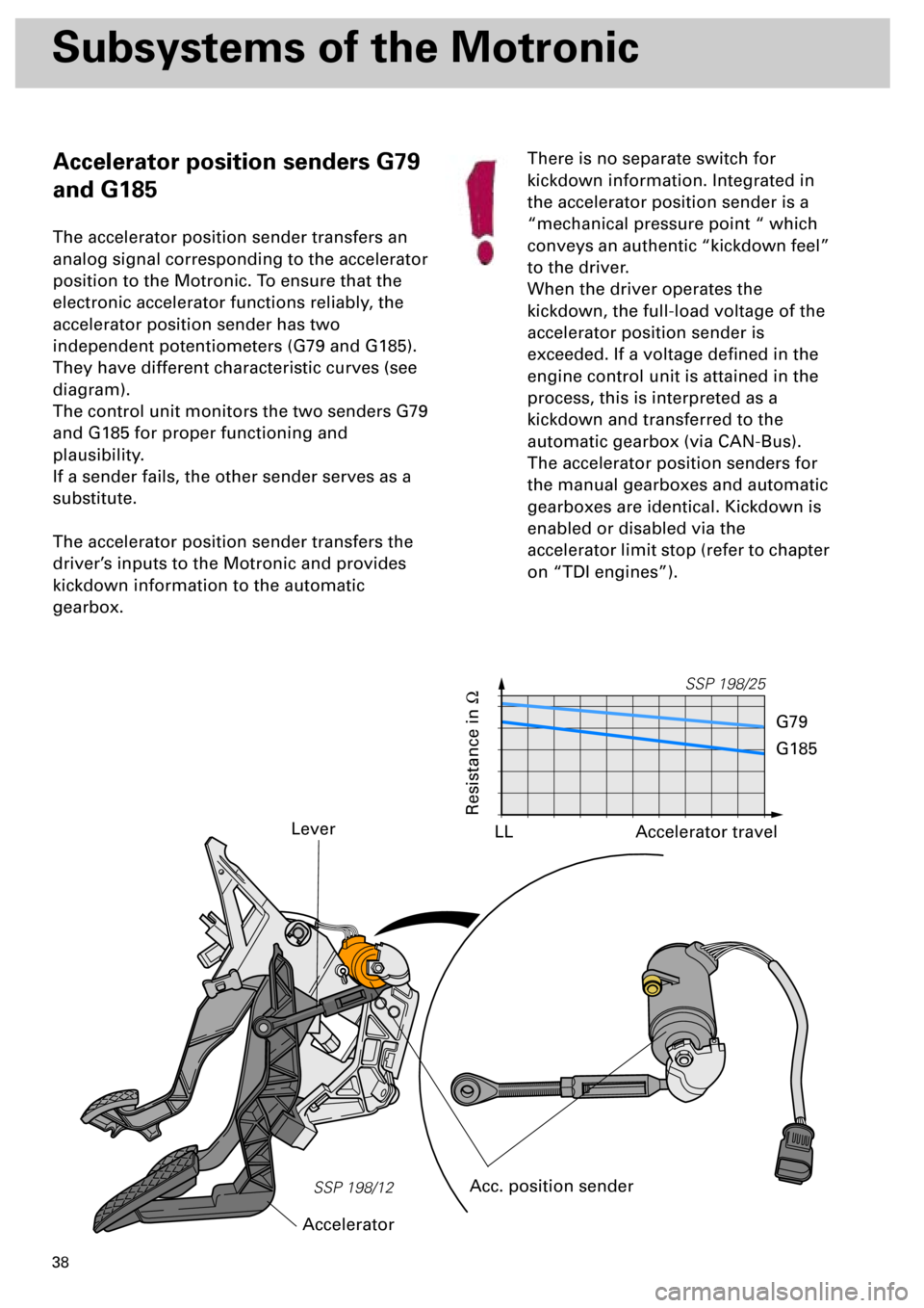
Accelerator position senders G79
and G185
The accelerator position sender transfers an
analog signal corresponding to the accelerator
position to the Motronic. To ensure that the
electronic accelerator functions reliably, the
accelerator position sender has two
independent potentiometers (G79 and G185).
They have different characteristic curves (see
diagram).
The control unit monitors the two senders G79
and G185 for proper functioning and
plausibility.
If a sender fails, the other sender serves as a
substitute.
The accelerator position sender transfers the
driver’s inputs to the Motronic and provides
kickdown information to the automatic
gearbox.
Lever
Acc. position sender
AcceleratorThere is no separate switch for
kickdown information. Integrated in
the accelerator position sender is a
“mechanical pressure point “ which
conveys an authentic “kickdown feel”
to the driver.
When the driver operates the
kickdown, the full-load voltage of the
accelerator position sender is
exceeded. If a voltage defined in the
engine control unit is attained in the
process, this is interpreted as a
kickdown and transferred to the
automatic gearbox (via CAN-Bus).
The accelerator position senders for
the manual gearboxes and automatic
gearboxes are identical. Kickdown is
enabled or disabled via the
accelerator limit stop (refer to chapter
on “TDI engines”).
SSP 198/25
Resistance in
W
Accelerator travel
G79
G185
LL
Page 39 of 72
40
SSP 198/28
Subsystems of the Motronic
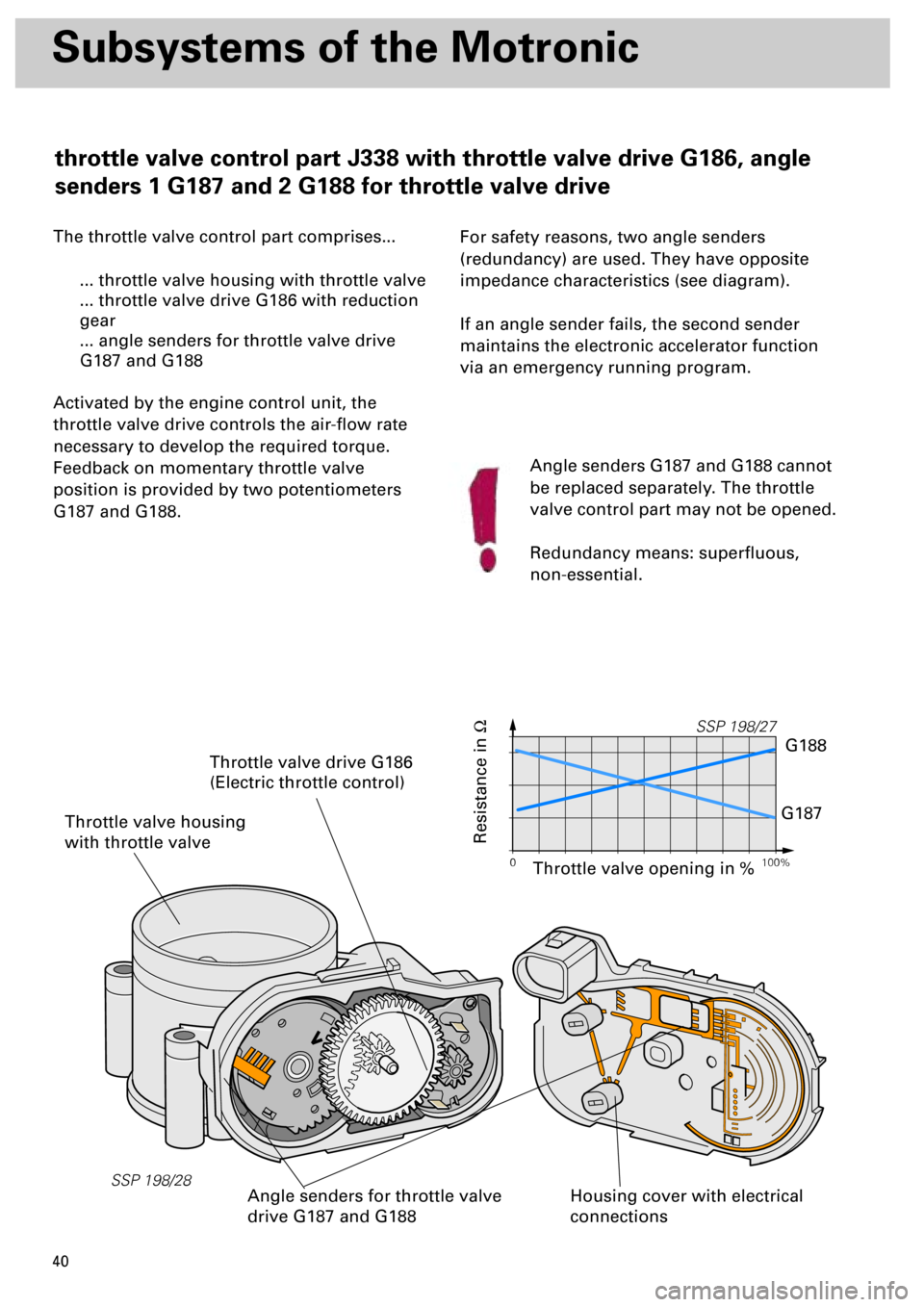
The throttle valve control part comprises...
... throttle valve housing with throttle valve
... throttle valve drive G186 with reduction
gear
... angle senders for throttle valve drive
G187 and G188
Activated by the engine control unit, the
throttle valve drive controls the air-flow rate
necessary to develop the required torque.
Feedback on momentary throttle valve
position is provided by two potentiometers
G187 and G188.
For safety reasons, two angle senders
(redundancy) are used. They have opposite
impedance characteristics (see diagram).
If an angle sender fails, the second sender
maintains the electronic accelerator function
via an emergency running program.
Throttle valve housing
with throttle valve
Housing cover with electrical
connections
Throttle valve drive G186
(Electric throttle control)
Angle senders for throttle valve
drive G187 and G188
Resistance in
W
Angle senders G187 and G188 cannot
be replaced separately. The throttle
valve control part may not be opened.
Redundancy means: superfluous,
non-essential.
0 100%
SSP 198/27
G188
G187
Throttle valve opening in %
throttle valve control part J338 with throttle valve drive G186, angle
senders 1 G187 and 2 G188 for throttle valve drive
Page 46 of 72
47
SSP/198/13
Exhaust gas temperature sender
G235 and G236
To facilitate exhaust gas temperature control,
the exhaust gas temperature must be recorded
to a high degree of accuracy.
An accuracy of ± 5 °C is achieved in the
measurement range from 950 °C to 1025 °C.
The exhaust gas temperature sender is located
inside the exhaust manifold upstream of the
exhaust gas turbocharger.
It comprises a measuring sensor and
evaluation electronics.
The measuring sensor and the control unit are
permanently connected by means of a
shielded, heat-resistant wire.
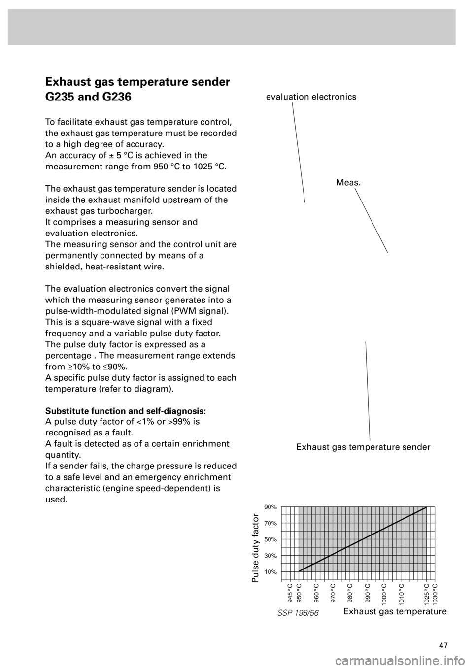
The evaluation electronics convert the signal
which the measuring sensor generates into a
pulse-width-modulated signal (PWM signal).
This is a square-wave signal with a fixed
frequency and a variable pulse duty factor.
The pulse duty factor is expressed as a
percentage . The measurement range extends
from
³
10% to
£
90%.
A specific pulse duty factor is assigned to each
temperature (refer to diagram).
Substitute function and self-diagnosis:
A pulse duty factor of <1% or >99% is
recognised as a fault.
A fault is detected as of a certain enrichment
quantity.
If a sender fails, the charge pressure is reduced
to a safe level and an emergency enrichment
characteristic (engine speed-dependent) is
used.
Exhaust gas temperature sender
evaluation electronics
SSP 198/56
90%
70%
50%
30%
10%
945°C
950°C
960°C
970°C
980°C
990°C
1000°C
1010°C
1025°C
1030°C
Exhaust gas temperature
Pulse duty factor
Meas.
Page 54 of 72
55
SSP 198/60
1436251
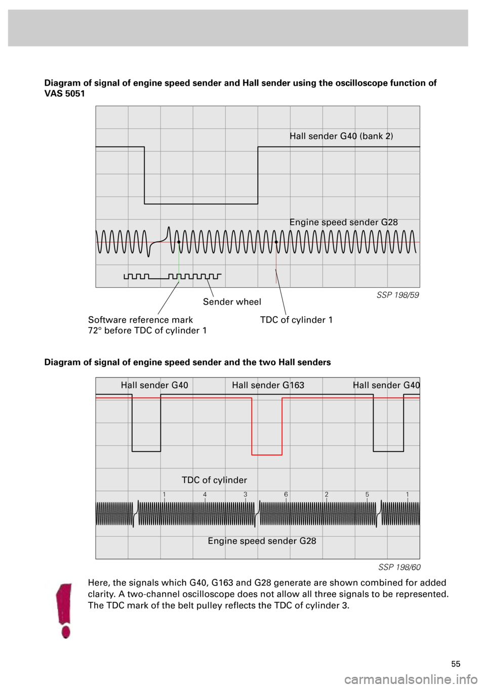
Diagram of signal of engine speed sender and Hall sender using the oscilloscope function of
VAS 5051
SSP 198/59
Software reference mark
72° before TDC of cylinder 1TDC of cylinder 1
Sender wheelHall sender G40 (bank 2)
Engine speed sender G28
Diagram of signal of engine speed sender and the two Hall senders
Hall sender G163 Hall sender G40
TDC of cylinder
Engine speed sender G28 Hall sender G40
Here, the signals which G40, G163 and G28 generate are shown combined for added
clarity. A two-channel oscilloscope does not allow all three signals to be represented.
The TDC mark of the belt pulley reflects the TDC of cylinder 3.
Page 61 of 72
62
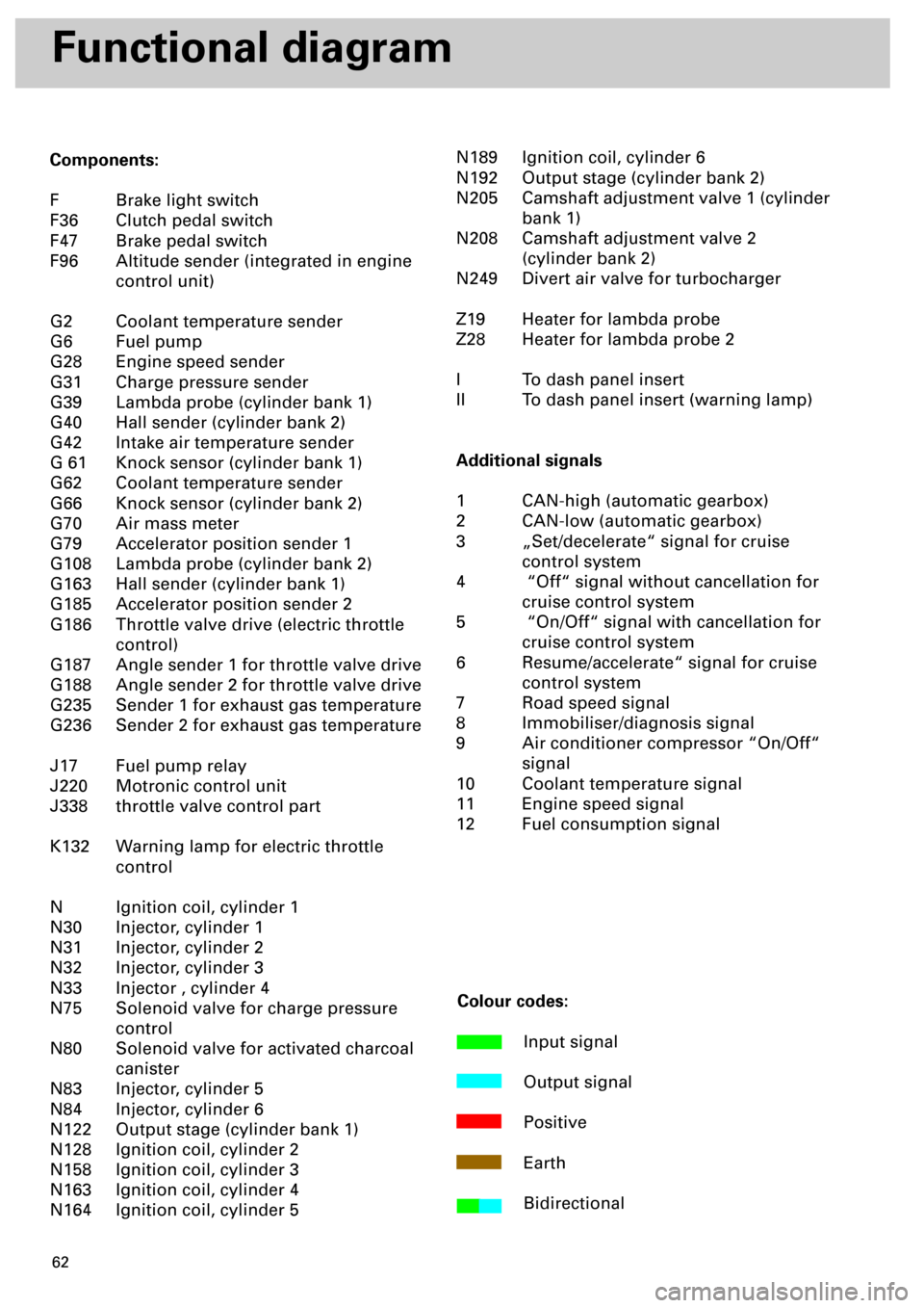
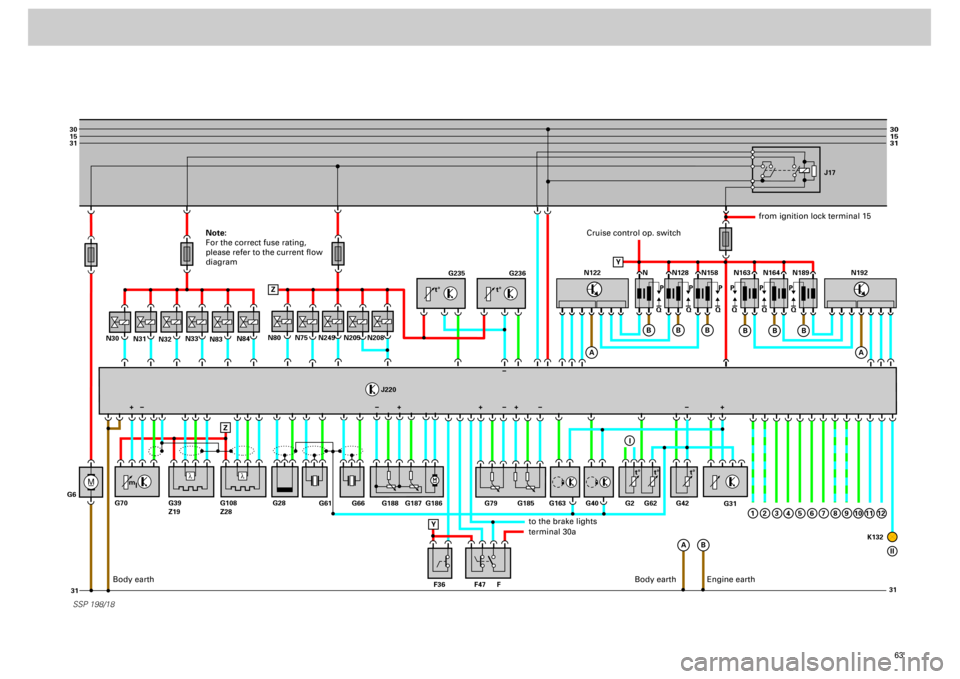
Functional diagram
Components:
F Brake light switch
F36 Clutch pedal switch
F47 Brake pedal switch
F96 Altitude sender (integrated in engine
control unit)
G2 Coolant temperature sender
G6 Fuel pump
G28 Engine speed sender
G31 Charge pressure sender
G39 Lambda probe (cylinder bank 1)
G40 Hall sender (cylinder bank 2)
G42 Intake air temperature sender
G 61 Knock sensor (cylinder bank 1)
G62 Coolant temperature sender
G66 Knock sensor (cylinder bank 2)
G70 Air mass meter
G79 Accelerator position sender 1
G108 Lambda probe (cylinder bank 2)
G163 Hall sender (cylinder bank 1)
G185 Accelerator position sender 2
G186 Throttle valve drive (electric throttle
control)
G187 Angle sender 1 for throttle valve drive
G188 Angle sender 2 for throttle valve drive
G235 Sender 1 for exhaust gas temperature
G236 Sender 2 for exhaust gas temperature
J17 Fuel pump relay
J220 Motronic control unit
J338 throttle valve control part
K132 Warning lamp for electric throttle
control
N Ignition coil, cylinder 1
N30 Injector, cylinder 1
N31 Injector, cylinder 2
N32 Injector, cylinder 3
N33 Injector , cylinder 4
N75 Solenoid valve for charge pressure
control
N80 Solenoid valve for activated charcoal
canister
N83 Injector, cylinder 5
N84 Injector, cylinder 6
N122 Output stage (cylinder bank 1)
N128 Ignition coil, cylinder 2
N158 Ignition coil, cylinder 3
N163 Ignition coil, cylinder 4
N164 Ignition coil, cylinder 5N189 Ignition coil, cylinder 6
N192 Output stage (cylinder bank 2)
N205 Camshaft adjustment valve 1 (cylinder
bank 1)
N208 Camshaft adjustment valve 2
(cylinder bank 2)
N249 Divert air valve for turbocharger
Z19 Heater for lambda probe
Z28 Heater for lambda probe 2
I To dash panel insert
II To dash panel insert (warning lamp)
Additional signals
1 CAN-high (automatic gearbox)
2 CAN-low (automatic gearbox)
3 „Set/decelerate“ signal for cruise
control system
4 “Off“ signal without cancellation for
cruise control system
5 “On/Off“ signal with cancellation for
cruise control system
6 Resume/accelerate“ signal for cruise
control system
7 Road speed signal
8 Immobiliser/diagnosis signal
9 Air conditioner compressor “On/Off“
signal
10 Coolant temperature signal
11 Engine speed signal
12 Fuel consumption signal
Colour codes:
Input signal
Output signal
Positive
Earth
Bidirectional
Page 62 of 72
63
M
30
15
31
31 31
30
15
31
_
G6N31
N32N33N80
J220
N83N84
N30
N75
N249
N205
N208
SSP 198/18
G235
G236
G31
N N128J17
N158 N163 N164 N189
Q PPPPPP
QQ QQQ
A
A
B Z
ZB
B
B
N122
A
B
B
B
1
N192
G61
G66 G188 G187 G186 G79
F47 F36 FG163 G40 G62G2 G42
K132 G185
G28 G70 G39
Z19G108
Z28
Y
+
Y
I
2
3
4
5
6
7
8
9
10
11
12
II
l
l
t° t°
m
lt° t° t°
+++ +
Cruise control op. switch
from ignition lock terminal 15
to the brake lightsterminal 30a
Body earth
Engine earth
Note:
For the correct fuse rating,
please refer to the current flow
diagram
Body earth
Page 69 of 72
70
Power transmission
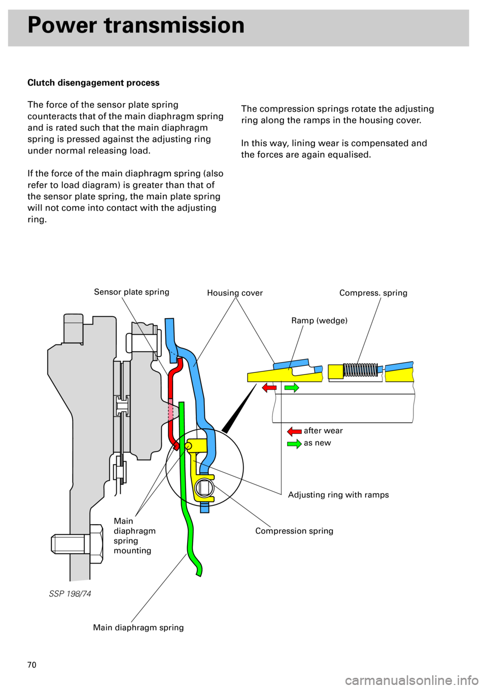
Clutch disengagement process
The force of the sensor plate spring
counteracts that of the main diaphragm spring
and is rated such that the main diaphragm
spring is pressed against the adjusting ring
under normal releasing load.
If the force of the main diaphragm spring (also
refer to load diagram) is greater than that of
the sensor plate spring, the main plate spring
will not come into contact with the adjusting
ring.
The compression springs rotate the adjusting
ring along the ramps in the housing cover.
In this way, lining wear is compensated and
the forces are again equalised.
SSP 198/74
Main diaphragm spring
Sensor plate springHousing cover
Adjusting ring with ramps
Compress. spring
Compression spring
Main
diaphragm
spring
mounting
Ramp (wedge)
after wear
as new