battery AUDI S5 COUPE 2016 Owners Manual
[x] Cancel search | Manufacturer: AUDI, Model Year: 2016, Model line: S5 COUPE, Model: AUDI S5 COUPE 2016Pages: 264, PDF Size: 66.92 MB
Page 5 of 264
.... N
0 Ico ....
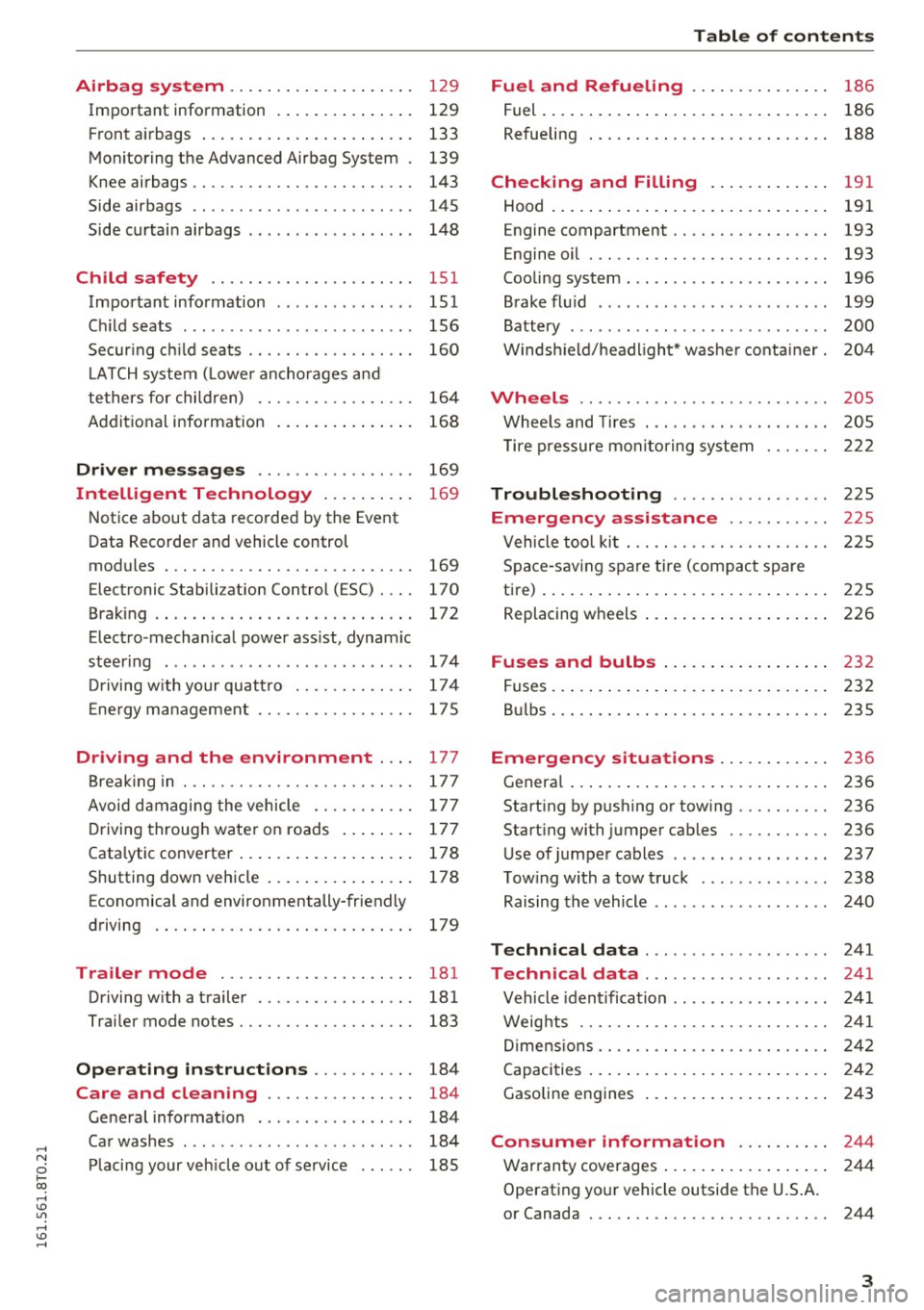
Important information . . . . . . . . . . . . . . . 129
F ront a irbags . . . . . . . . . . . . . . . . . . . . . . . 133
Mon itoring the Advanced Airbag System . 139
K nee airbags . . . . . . . . . . . . . . . . . . . . . . . . 143
Side airbags . . . . . . . . . . . . . . . . . . . . . . . . 145
Side curtai n airbags . . . . . . . . . . . . . . . . . . 14 8
Ch ild safety . . . . . . . . . . . . . . . . . . . . . . 151
Important information . . . . . . . . . . . . . . . 151
Ch ild seats . . . . . . . . . . . . . . . . . . . . . . . . . 156
Secur ing c hild seats . . . . . . . . . . . . . . . . . . 160
L ATCH system ( Lowe r ancho rages and
te thers for chi ldren) . . . . . . . . . . . . . . . . . 164
Addit ional information
168
Driver messages . . . . . . . . . . . . . . . . . 169
Intelligent Technology . . . . . . . . . . 169
N otice about data recorded by the Event
Data Recorde r and vehicle control
modules . . . . . . . . . . . . . . . . . . . . . . . . . . . 169
Elect ronic Stabilization Control (ESC) . . . . 170
Brak ing . . . . . . . . . . . . . . . . . . . . . . . . . . . . 172
Elect ro-mechan ica l power ass ist, dynamic
steer ing . . . . . . . . . . . . . . . . . . . . . . . . . . . 174
Dr iving w ith your quat tro . . . . . . . . . . . . . 17 4
E ne rgy ma nagement . . . . . . . . . . . . . . . . . 17 5
Driving and the environment ... . 177
B reaking in . . . . . . . . . . . . . . . . . . . . . . . . . 177
Avoid damaging the vehicle . . . . . . . . . . . 177
D riving throug h water on roads . . . . . . . . 177
Cata lytic converter . . . . . . . . . . . . . . . . . . . 178
Shutting down vehicle . . . . . . . . . . . . . . . . 178
Economical and environmentally-friendly
driving . . . . . . . . . . . . . . . . . . . . . . . . . . . . 179
Trailer mode . . . . . . . . . . . . . . . . . . . . . 181
Driving w ith a trailer . . . . . . . . . . . . . . . . . 181
Trai ler mode notes. . . . . . . . . . . . . . . . . . . 183
Operating instructions . . . . . . . . . . . 184
Care and cleaning . . . . . . . . . . . . . . . . 184
Ge neral information . . . . . . . . . . . . . . . . . 184
Ca r washes . . . . . . . . . . . . . . . . . . . . . . . . . 184
Pl acing your ve hicle out of se rvice . . . . . . 185
Table of contents
Fuel and Refueling . . . . . . . . . . . . . . .
186
Fuel. ... .. .. .. .. .. .... . ..... ... .. .. 186
Refueling . . . . . . . . . . . . . . . . . . . . . . . . . . 188
Checking and Filling . . . . . . . . . . . . . 191
Hood . . . . . . . . . . . . . . . . . . . . . . . . . . . . . . 191
Engine compartment . . . . . . . . . . . . . . . . . 193
Engine oil . . . . . . . . . . . . . . . . . . . . . . . . . . 193
Cooling system . . . . . . . . . . . . . . . . . . . . . . 196
Brake fl uid .. .. .. .. .... ...... ... .. .. 199
Battery . . . . . . . . . . . . . . . . . . . . . . . . . . . . 200
W indsh ield/headlight* washer conta iner. 204
Wheels ........ .. ................. 205
Whee ls and Tires . . . . . . . . . . . . . . . . . . . . 205
T ire p ressure monito ring sys tem 222
Troubleshooting . . . . . . . . . . . . . . . . . 225
Emergency assistance . . . . . . . . . . . 225
Vehicle too l ki t . . . . . . . . . . . . . . . . . . . . . . 225
Space -sav ing spare tir e ( compac t spare
t ire) . . . . . . . . . . . . . . . . . . . . . . . . . . . . . . . 225
Replacing w heels . . . . . . . . . . . . . . . . . . . . 226
Fuses and bulbs . . . . . . . . . . . . . . . . . . 232
Fuses ... .. .. .. .. .. .... . ..... ... .. .. 232
B ul bs . . . . . . . . . . . . . . . . . . . . . . . . . . . . . . 235
Emergency situations . . . . . . . . . . . . 236
Genera l . . . . . . . . . . . . . . . . . . . . . . . . . . . . 236
Start ing by pushing or tow ing . . . . . . . . . . 236
Start ing with jumper cables . . . . . . . . . . . 236
Use of jumper cables . . . . . . . . . . . . . . . . . 237
T ow ing with a tow t ruck . . . . . . . . . . . . . . 238
Raising the vehicle . . . . . . . . . . . . . . . . . . . 240
Technical data . . . . . . . . . . . . . . . . . . . . 241
Technical data . . . . . . . . . . . . . . . . . . . . 241
Vehicle iden tification . . . . . . . . . . . . . . . . . 241
Weig hts . . . . . . . . . . . . . . . . . . . . . . . . . . . 241
Di mens ions . . . . . . . . . . . . . . . . . . . . . . . . . 242
Capaci ties . . . . . . . . . . . . . . . . . . . . . . . . . . 2 42
Gasoline engines . . . . . . . . . . . . . . . . . . . . 243
Consumer informat ion ...... .. .. 244
War ranty coverages . . . . . . . . . . . . . . . . . . 244
Operating your vehicle outside the U.S.A.
or Canada . . . . . . . . . . . . . . . . . . . . . . . . . . 244
3
Page 15 of 264
.... N
0 Ico ....
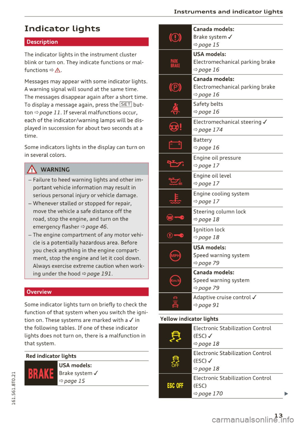
Description
The indicator lights i n the inst rument cluste r
b link or t urn on. They ind icate func tions or ma l
f u nctions ¢& .
Messages may appea r with some indica to r li ghts.
A wa rni ng sig nal w ill sound at the same time.
The messages disappear aga in after a short t ime.
To d isp lay a mess age ag ai n, p ress t he
ISE TI bu t
ton ¢
page 11. If severa l ma lf u nctions occur,
each of the indicator/warning lamps will be dis
p layed i n succession for abo ut two seconds at a
time.
Some ind icators ligh ts in the disp lay can turn o n
in several colo rs.
8_ WARNING
- Failure to heed warning lights and other im
portant vehicle informat ion may result in
serious persona l injury or vehicle damage.
- Whenever sta lled or stopped for repair,
move th@ vehicle a safe distance off th@
road , stop the engine, and turn on t he
eme rgency flasher ¢
page 46.
-The engine compartment of any motor vehi
cle is a potentia lly hazardous a rea . Befo re
yo u check any thing in the engine compart
m en t, stop the engi ne a nd let it cool dow n.
Alway s exe rcise ex treme c aution w hen work
ing unde r the ho od ¢
page 191.
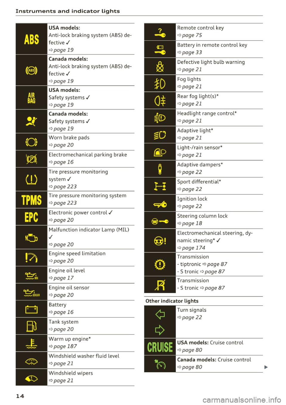
Overview
Some in dicator lights turn o n briefly to che ck the
f u nction o f that system when you swi tch the ig ni
tion o n. These systems are marke d with a ./ in
the following tables . If one of these indicator
lights does not turn on, there is a malfunction in
that system.
Red indicator lights
--------------
US A models:
Brake system ./
¢page 15
Instruments and ind icator lights
Canada model s:
Br ake system ./
¢page 15
USA models:
Electromechanical parking brake
¢ page 16
Canada models:
El ectromec hanic al p arking b rake
¢ page 16
Safety be lts
¢ page 16
Electromechanical steering ./
¢page 174
Battery
¢page 16
Engine oi l pressu re
¢ page 17
En gine o il level
¢ page 17
En gine cooling sys tem
¢ page 17
Steering co lumn lock
¢ page 18
Ig nitio n lock
¢ page 18
USA models:
Speed warning system
¢page 79
Canada models:
Speed warning system
¢page 79
Ad ap tive cruise cont ro l./
¢ page 91
Yellow indicator lights
--------------
Elec tronic Stab ilizati on Contro l
(ESC) ./
¢page 18
El ec tronic Stab ilization Contro l
( ES C) ./
¢page 18
Electronic Stab ilization Contro l
(ESC)
¢ page 170
13
Page 16 of 264
Instruments and indicator lights
TPMS
-~--
14 USA models
:
Anti-lock brak ing system (ABS) de
fective,/
¢ page 19
Canada mod els :
Anti-lock brak ing system (A BS) de
fective,/
¢ page 19
USA models :
Safety systems ./
¢page 19
Canada models :
Safety systems ./
¢page 19
Worn brake pads
¢page20
Elect romechan ical park ing brake
¢page 16
Tire pressure monitoring
system ,/
¢page 223
Tire pressure monitor ing system
¢page223
Electronic power control ,/
¢page20
Malf unct io n ind icator Lamp (MIL)
,I
c::> page 20
Engi ne speed limitat ion
c::> page20
Engine oil level
c::> page 17
Engine oil sensor
c::>page20
Battery
c::>page 16
Tank system
c::>page20
Wa rm up eng ine *
¢page 187
Windshield washe r fl uid leve l
¢page 21
Windshield wipers
¢page 21
Remote control key
¢ page 75
Battery in remote control key
¢page 33
Defect ive light bulb wa rning
<=> page 21
Fog lights
¢page 21
Rear fog ligh t(s)*
c> page 21
Headlight range control*
c> page 21
Adaptive light*
c>page 21
Light-/rai n sensor*
c> page 21
Adaptive dampers*
c>page22
Sport different ial*
<=> page22
Ig nition loc k
c>page22
Steering co lumn lock
¢ page 18
Elec tromechanical stee ring, dy
nam ic stee ring *,/
c>page 174
Transmission
- tipt ronic
c> page 87
- S tron ic c::> page 87
Transmission
- S tron ic
¢page 87
Other indicator light s
~--==------------Turn signals
<=>page22
USA mode ls: Cruise cont rol
c> page80
Canada model s: Cruise control
c> page 80
Page 18 of 264
Instruments and indicator lights
-Always keep in min d that afte r severa l brake
applications, you will need greate r pressure
on the brake pedal t o stop you r vehicle. Do
not re ly on strained brakes to respond w ith
ma ximum stopping power in c rit ical situa
t ions. You must allow for increas ed braki ng
di stan ces. The e xtra dist ance used up by
fa din g brak es c oul d lead to a n accid ent.
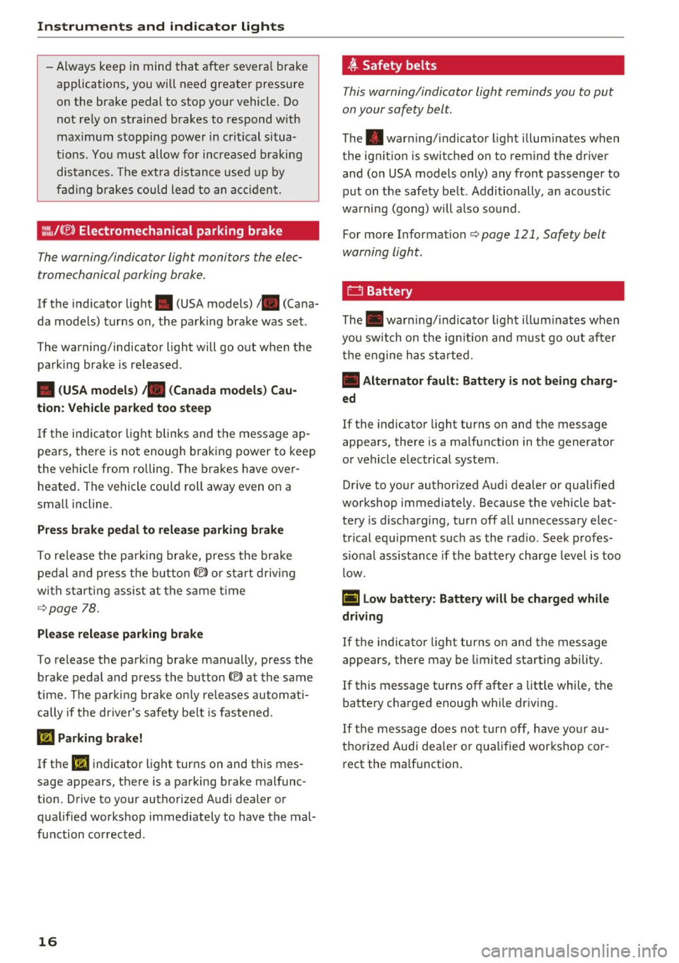
:ill.IC®) Electromechanical parking brake
The warning/indicator light monitors th e elec
trome chanical parking brak e.
If the ind icator lig ht . (USA models) ;II (Cana
da models) t urns on , the park ing brake was set .
The warning/indicator light will go o ut when the
pa rking brake is re leased.
• (USA models ) /. (Canada models) Cau
tion: Vehicle parked too steep
If th e ind ic ator lig ht blinks and t he message ap
pea rs, there is not eno ugh bra king power to keep
the vehicle from ro llin g. The bra kes have over
heate d. The vehicle could ro ll away even on a
sma ll incline .
Press brake pedal to release parking brake
To re lease the pa rk ing bra ke, press the bra ke
pe dal and pr ess t he bu tton<®) or start driv ing
w ith s tarti ng assis t at the s ame t ime
¢ page 78 .
Please release parking brake
To re lease the park ing brake ma nually, press the
b rake pedal and press the button<®> at the same
time . The parking brake o nly re leases automati
cally if the dr iver's safety be lt is fastened.
El Parking brake!
If the El indicato r light turns on and this mes
sage appears, there is a pa rking brake mal func
tion. D rive to your authorized Aud i dealer or
qua lified workshop immed iate ly to have the mal
f u nction co rrected .
16
~ Safety belts
This warning/indicator light reminds you to put
on your safety belt.
The . warn ing/ indicator light illum inates when
the ignit io n is switched on to rem ind t he driver
and (o n USA models on ly) any front passenge r to
put on t he safety be lt . Additionally, a n aco ust ic
w arning (gong) w ill also so und.
Fo r more Information
¢ page 121 , Safety belt
warning light .
f::::l Battery
The. war ning/ indica to r li ght illum inates when
yo u s witch on the ig nition an d m ust go out afte r
th e e ngine h as st arte d.
• Alternator fault : Battery is not being charg
ed
If the indicato r light turns on and the message
appears, the re is a ma lfu nction in t he generator
o r vehicle e lectr ica l system .
D rive to your authorized A udi dealer or qualified
workshop immediately . Because the vehicle bat
tery is d ischa rging , tur n off all unnecessa ry elec
trical eq uipme nt such as the rad io . Seek p ro fes
s io na l assis tance if the battery charge leve l is too
l ow.
(•) Low battery: Battery will be charged while
driving
If the indicato r light turns on and the message
appears, there may be limited sta rting ability.
If this message t urns off after a little w hil e, t he
ba tte ry c harge d enough while dr iv ing .
I f the mess age does no t turn off, h ave yo ur au
thorized Audi dea le r or qualified wor ks hop co r
r ect the ma lf u nction .
Page 30 of 264
Driver information s ystem
Fuel economy messages
Applies to vehicles: with trip computer with efficiency pro
gram
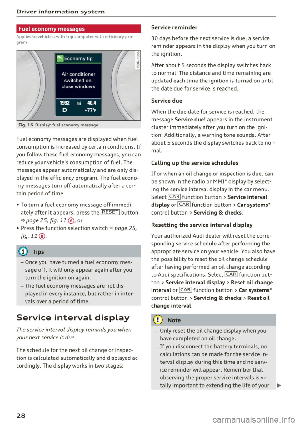
F ig. 16 D isplay: fuel eco nomy message
Fue l economy messages are displayed when fue l
consumption is inc reased by certain conditions. If
you follow these fuel economy messages, you can reduce your vehicle's consumption of fuel. The
messages appear automatically and are only dis
p layed in the eff iciency program . The fuel econo
my messages turn off automat ica lly afte r ace r
tain period of t ime.
"' To turn a fuel economy message off immed i
ate ly after it appears , press t he I R ESE T I button
¢ page 25, fig. 11 @ , or
"' Press t he f unct ion sele ct io n sw itch
~ page 2 5,
fig. 11
® ·
(D Tips
- Once you have t urned a fue l economy mes
sage off, it will on ly appea r again after you
turn the ig nition on ag ain.
- T he fuel economy messages a re not d is
p layed in every ins tance, but rather in in ter
v al s over a per io d of t ime.
Service interval display
The service interval display reminds you when
your next service is due .
The schedule for the next oil change o r inspec
tion is calc ulated a utomatically and displayed ac
cord ingly. The display works in two stages:
28
Service reminder
3 0 days before the next service is due , a servi ce
r eminder appears in the display when you turn on
the ignition .
After abou t
5 seconds the display swit ches bac k
to normal. The dist ance a nd time rem aining are
u pda ted each time the ignit ion is turned on unt il
the date due for service is reached.
Service due
Whe n the d ue date for se rvice is rea ched, the
message
Service due! appears in the inst rument
cl uster immed iate ly after you tu rn o n the igni
tion . Add itiona lly, a warn ing tone sounds. A fter
about
5 seconds the display switches back to nor
mal.
Calling up the service schedules
I f or w hen an oil change o r inspec tion is due, can
be shown in the radio or MMI * display by se lect
i ng the service interval display in the car menu.
Se lect
I CAR I fu nction button > Se rvice interval
display
or ! CAR I function button > Car systems *
control button > Ser vicing & checks .
Resetting the s ervice interval display
Yo ur a utho rized Aud i dea ler will rese t the corre
sponding service schedu le after performing the
approp riate service on your vehicle . You also have
the possibility to reset t he oi l change schedule
after having pe rformed an oil change accord ing
to Audi specifications. Select
I CA R I fu nction but
ton
> Service interval display > Re set oil change
interval
or ICA RI fu nction button > Car systems *
control button > Servicing & check s > Reset oil
change interval.
(D Note
- Only reset the oil c hange display when you
h ave completed an o il change.
- If you disconnect the battery term inals, no
calcu lations can be made for the se rvice in
te rv al display dur ing th is time and no se rv
i c e rem inder will appear. Remembe r th at
ob serv ing the pro per serv ice intervals is vi-
ta lly im po rt an t to extending the life o f your .,.
Page 31 of 264
,-1 N
0 1-CX)
rl I.Cl U"I
,-1 I.Cl ......
vehicle, particularly the engine, and main
taining its value. Even if the mileage driven
is low, the maximum period of one year
from one service to the next must not be ex
ceeded.
@ Tips
The informat ion in the Service Rem inder re
mains stored even when the vehicle battery is
disconnected.
On Board Diagnostic
System (OBD)
Malfunction Indicator Lamp (MIL)
The Malfunction Indicator Lamp (MIL) ¢..ift in the
instrument cluster is part of the On-Board Diag
nostic (OBD II) system .
The warning/indicator light illuminates when the
ignition is switched on and goes out after the en
gine starts and the idle has stabilized. This indi
cates that the MIL is working properly .
If the light does not go out after the engine is
started, or illuminates while you are driving, a malfunction may exist in the engine system.
If
the light illuminates, the catalytic converter
could be damaged.
Continue driving
with reduced power (avoiding
sustained high speeds and/or rapid accelera
tions) and have the condition corrected. Contact
your authorized Audi dealer.
If the light illuminates, the electronic speed limiter may also be malfunctioning. For more infor
mation
¢ page 29, Electronic speed limiter.
An improperly closed fuel filler cap may also
cause the MIL light to illuminate ¢
page 188.
Driver in forma tion system
On-Board Diagnostics
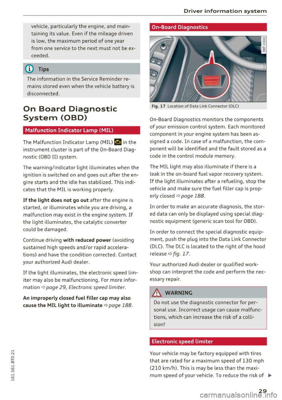
Fig. 17 Loca tion of Data Link Connector (DLC)
On-Board Diagnostics monitors the components
of your emission control system. Each monitored
component in your engine system has been as
s igned a code. In case of a malfunction, the com
ponent will be identified and the fault stored as a
code in the control module memory.
The MIL light may also illuminate if there is a
leak in the on-board fuel vapor recovery system.
If the light illuminates after a refueling, stop the
vehicle and make sure the fuel f iller cap is prop
erly closed
¢ page 188.
In order to make an accurate diagnosis, the stor
ed data can only be displayed using special diag
nostic equipment (gener ic scan tool for OBD).
In order to connect the special d iagnost ic equip
ment, push the p lug into the Data L ink Connector
(DLC). The DLC is located to the right of the hood
release
¢ fig. 17.
Your authorized Audi dealer or qualified work
shop can interpret the code and perform the nec
essary repair.
.&, WARNING
Do not use the diagnostic connector for per
sonal use. Incorrect usage can cause malfunc
tions, which can increase the risk of a co lli
sion!
Electronic speed limiter
Your vehicle may be factory equipped with tires
that are rated for a maximum speed of 130 mph (210 km/h). This is may be less than the maxi
mum speed of your vehicle . To reduce the risk of .,.
29
Page 35 of 264
-Do not remove the key from the ignition
lock until the vehicle has come to a com
plete stop . Otherwise the steer ing column
lock could suddenly engage -causing the
risk of an accident .
(D Tips
-The operation of the remote control key can
be temporarily d isrupted by interference
from transmitters in the vicinity of the vehi
cle work ing in the same frequency range
(e .g. a cell phone, radio equipment).
- For security reasons, replacement keys are
only available from authorized Aud i dea ler .
- For Declaration of Compliance to Un ited
States FCC and Industry Canada regulations
<::>page 247.
Removing the mechanical key
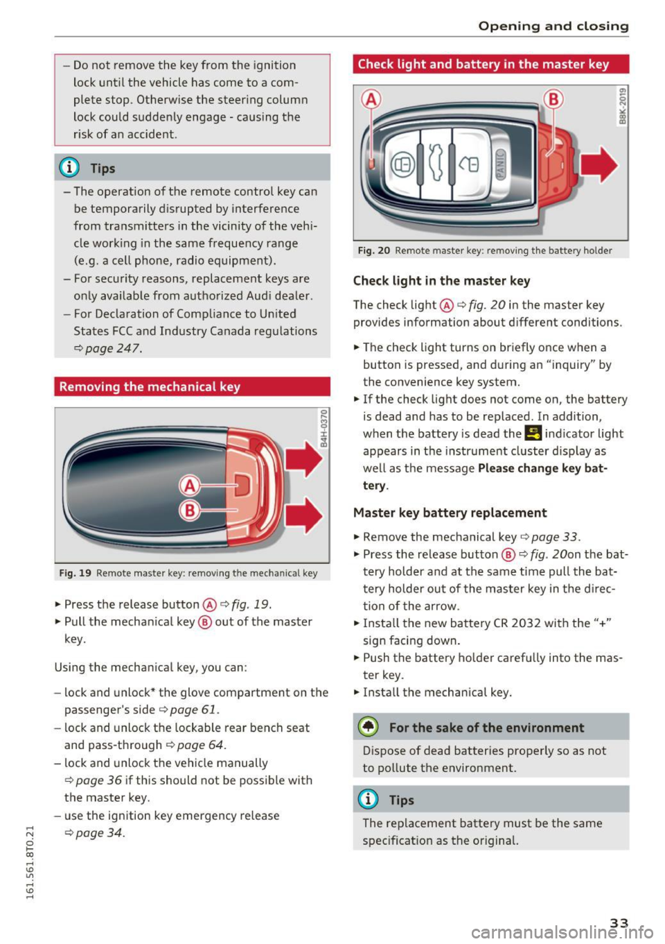
F ig. 19 Remote master key: removing t he m ec hani ca l key
.,. Press the release button @r=> fig. 19.
.,. Pull the mechan ical key ® out of the master
key.
Using the mechan ical key, you can :
- lock and unlock* the glove compartment on the
passenger's side
c> page 61 .
-lock and unlock the lockable rear bench seat
and pass-through
c> page 64.
- lock and unlock the vehicle manually
c> page 36 if this should not be possible with
the master key.
- use the ign ition key emergency release
;::; opage 34.
0 1-CX)
rl I.Cl U"I
rl I.Cl rl
Open ing and closing
Check light and battery in the master key
Fig. 20 Remote master key: re moving the bat tery holder
Check light in the master key
The check light @r=> fig. 20 in the master key
provides information about d ifferent conditions .
.,. The check light turns on briefly once when a
button is pressed, and during an "inquiry" by
the convenience key system.
.,. If the check light does not come on, the battery
is dead and has to be replaced . In addition,
when the battery is dead the
Ill indicator light
appears in the instr ument cluster display as
well as the message
Please change key bat
tery .
Master key battery replacement
.,. Remove the mechanical key o page 33 .
.,. Press the re lease button ® o fig. 20on the bat
t ery holder and at the same time pull the ba t
tery holder out of the master key in the d irec
tion of the arrow .
.,. Insta ll the new battery CR 2032 with the"+"
sign facing down .
.,. Push the battery holder carefully into the mas
ter key .
.,. Install the mechanical key.
@) For the sake of the environment
Dispose of dead batteries properly so as not
to pollute the environment.
@ Tips
The replacement battery must be the same
specificat ion as the original.
33
Page 37 of 264
,-1 N
0 1-CX)
rl I.Cl U"I
,-1 I.Cl ......
"'To lock the vehicle, close the door and touch
the sensor in the door hand le
on ce ~ fig. 22
~ A in General description on page 31 . Do not
reach inside the door handle .
The vehicle can be locked and un locked at any
door . The remote control key cannot be more
than 1.5 m away from the door handle. It makes
no difference whether the master key is in your
jacket pocket or in your brief case .
If you grip the door handle while locking, this can
adversely affect the locking function.
It is not possible to re-open the doo r for a b rief
period directly after closing it. This allows you to
ensure that the doors are properly locked .
It depends on the settings i n the rad io or MMI*
whether the entire vehicle is unlocked or one of
the doors
~ page 36.
A WARNING
Read and follow all WARNINGS~&. in Gener
al description on page 31.
@ Tips
If your vehicle has been standing for an ex
tended period, please note the following:
- The proximity sensors are deactivated after
a few days to save power . You then have to
pull on the door handle once to unlock the
vehicle and a second time to open the vehi
cle.
- To p revent the battery from being d is
charged and to preserve your vehicle's abili
ty to start for as long as possible, the ener
gy management system gradua lly switches
off unnecessary convenience functions. It is
possible that you w ill not be ab le to unlock
your vehicle using these convenience func tions .
- Fo r Decla ration of Comp liance to Un ited
States FCC and Industry Canada regu lations
~ page 247.
Op enin g an d clos ing
Locking and unlocking the vehicle from
inside
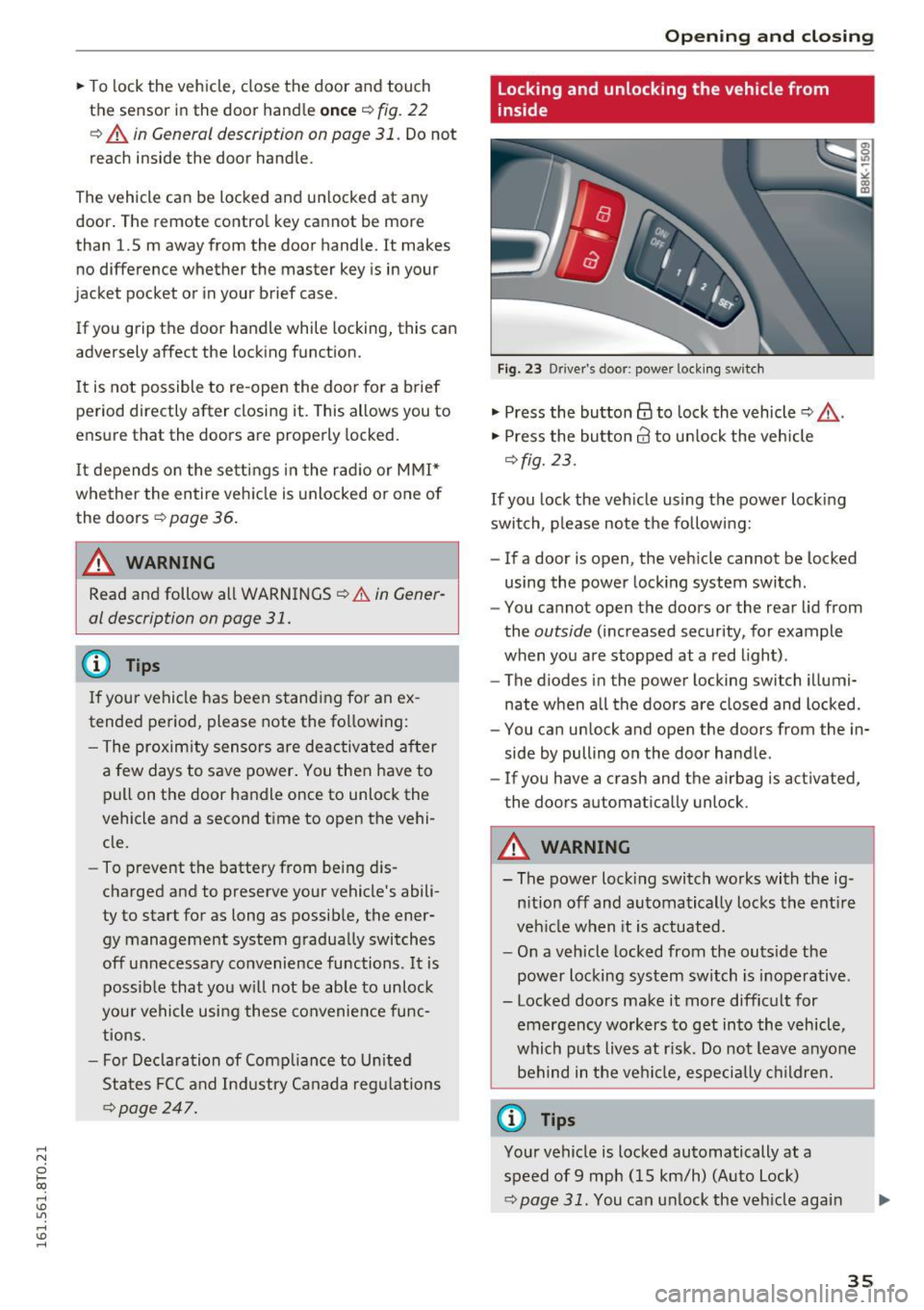
Fig. 23 Drive r's door; power lock ing sw itch
"' Press the button@ to lock the vehicle ~ &,.
"' Press the button 63 to un lock the veh icle
~ fig. 23.
If you lock the veh icle using the power lock ing
switch , please note the following:
- If a door is open, the veh icle cannot be locked
using the power locking system switch .
- You cannot open the doors or the rear lid from
the
outside (increased security, for example
when you are stopped at a red light) .
- The diodes in the power locking switch illumi
nate when a ll the doors are closed and locked .
- You can unlock and open the doors from the in
side by pulling on the door handle .
- If you have a crash and the airbag is act ivated,
the doors automatically unlock .
A WARNING
-- The power locking switch works with the ig-
n ition off and automatically locks the ent ire
veh icle when it is actuated.
- On a vehicle locked from the outs ide the
power locking system switch is inoperative .
- Locked doors make it more difficult for emergency workers to get into the vehicle,
which puts lives at r isk. Do not leave anyo ne
behind in the vehi cle, especially children.
@ Tips
Your vehicle is locked automatically at a
speed of 9 mph (15 km/h) (Auto Lock)
~ page 31. You can un lock the vehicle again
3 5
Page 41 of 264
.... N
0 Ico ....
tomatica lly close the window.
A WARNING
- When you leave your vehicle -even if only
br iefly- always remove the ign ition key . This
applies particularly when children rema in in
the vehicle. Otherw ise the children could
sta rt the eng ine or operate electr ical equ ip
ment (e .g . power windows). The power w in
dows are functional unt il the dr iver's door or
p assenger's door has been opened.
- Pay close attention when closing the win
dows to prevent p inching of hands o r limbs .
- When loc king the veh icle from outside, the
vehicle must be unoccupied since t he win
dows can no longer be opened in an emer
gency.
(D Tips
- When yo u open the doo rs, the windows au
tomati cally lower abou t 10 mm.
- After the ignition has been switched off, the
windows can st il l be opened or closed for
abo ut 10 m inutes. The window regula to rs
are not sw itched until the driver 's or pas
senger's door is opened .
Convenience opening/closing
The windows and the panoramic tilting sunroof
can be opened and closed with the mechanical
key or the emergency key.
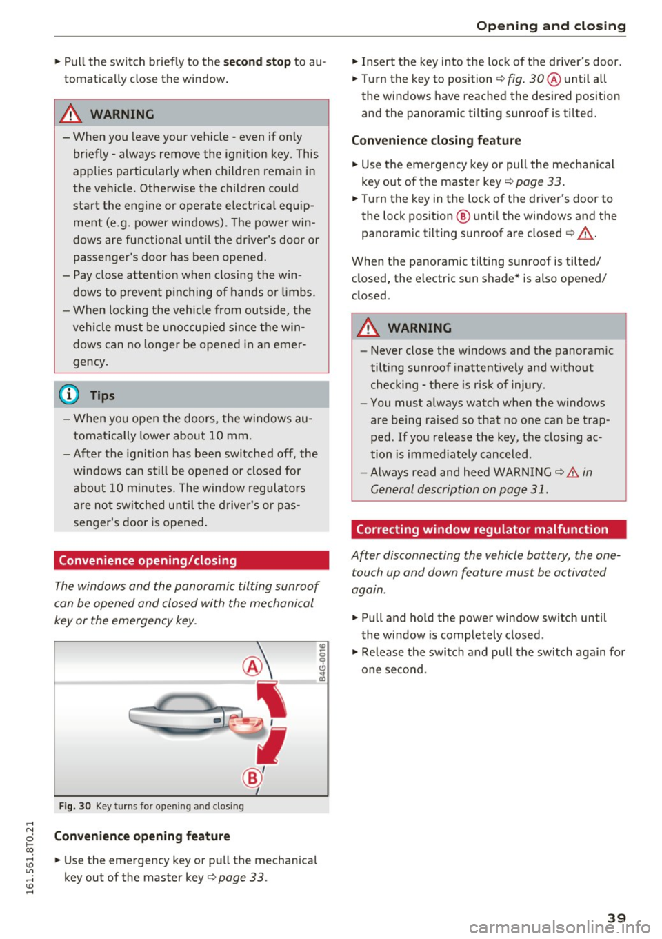
F ig . 3 0 Key tu rns fo r open ing a nd clos ing
Convenience opening feature
• Use the emergency key or pu ll the mechanical
key out of the master key
q page 33 .
-
Opening and cl osing
• Insert the key into the lock of the driver's door.
• Turn the key to position~
fig. 30@ until all
the windows have reached the desired position
and the panoramic ti lting sunroof is ti lted.
Convenience closing feature
• Use the emergency key or pull the mec hanical
key out o f the maste r key
q page 33.
• Turn the key in the lock of the driver's door to
the lock pos ition @ unti l the windows and the
panoram ic tilting sunroof are closed
q ,& .
When the panoramic tilting sunroof is tilted/
closed, the e lectric sun shade* is also opened/
closed.
A WARNING
-- Never close the w indows and the panoramic
tilt ing sunroof inattent ively and without
checking -the re is risk of injury.
- You must a lways watch when the windows
are being ra ised so that no o ne can be trap
ped. If you release the key, the clos ing ac
tion is immed iate ly canceled.
- Always read and heed WA RN ING
q .&. in
General description on page 31.
Correcting window regulator malfunction
After disconnecting the vehicle battery , the one
touch up and down feature must be activated
again.
• Pull and ho ld the power window switch until
the window is comp letely closed.
• Release the switch and pull the swi tch again for
one seco nd .
39
Page 90 of 264
Automatic transmission
Press the brake pedal and se lec t the desired se
lecto r lever positio n again. You can then continue
driving .
rm Transmission overheating: Please drive con
servatively .
The transm ission tempe rature has increased s ig
n ifi cant ly due to the spo rty dr ivin g manne r. Dr ive
i n a less sporty m anner until the temperature re
turns to the normal range and the indicator light
switches of.
rm Transmission malfunction: You can continue
driving
There is a system malfunct io n in the t rans mis
sion . Yo u may continue dr iving . Dr ive to your au
t hor ized Audi dea ler or qu alified rep air facilit y
soon to have t he malfunc tion cor rec ted .
rm Transmission malfunction: limited driving
functionality
There is a system malfunct io n in the transm is
sion . T he transmission is sw itchi ng to emergency
mode . This mode only shifts in to certai n gea rs o r
w ill no longer shift at all. The engine may s tall.
D rive to yo ur author ized Aud i dea le r o r q ualified
repair fac ility immediately to have the malfunc
tion corrected.
l'§J Iii Transmission malfunction: No reverse
You can continue driving
S tron ic tra nsmission: There is a system malfunc
tion in th e tra nsmission . The t ransmiss io n is
sw itching to emergency mode. This m ode only
shifts in to cer tain gears or will no longer sh ift at
al l. The eng ine may st all. You canno t engage the
reverse gear. Drive to your authorized A udi dealer
or qualified repair facility immediate ly to have
the ma lfunction co rrected.
rm Transmission malfunction: Stop vehicle and
shift to park .
Do not cont inue d riving. Select the P se lector lev
er pos ition and see yo ur author ized Aud i de aler
or qu alified rep air facility for assis tance .
(D Note
If the tra ns missi on switches to emergency
m ode, you s ho uld t ake the veh icle to a n au-
88
thorized Audi dea lership a s soon as possible
to have the condition corrected .
Selector lever emergency release
Applies to vehicles: with S tronic/tiptronic
I f the vehicle's power supply fail s, the sele ctor
lever con be released in on emergency.
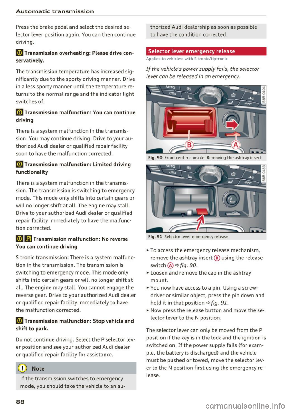
Fi g. 90 Fro nt ce nter co nso le: Re mov ing the as htr ay i nse rt
F ig . 91 Selector leve r em ergency release
"" To access the emergency re lease mechanism,
remov e the ashtray insert @ using th e release
sw itch @¢
fig. 90.
""Loosen and rem ove the ca p in t he a sh tra y
mou nt.
"" You now have access to a pin. Using a screw
driver or simi la r object, press t he p in down and
hold it in that position ¢
fig. 91.
"" Now press the release button and move these-
lector lever to the N posit ion.
The selector leve r ca n only be moved from the P
pos ition if the key is in the lock and the ignition is
switched on . If the power supply fails (for exam
ple, the battery is disc harged) and the veh icle
must be pushed or towed, move the selector lev
er to the N position fi rst usi ng the emergency re
l ease .