display AUDI S6 2009 Workshop Manual
[x] Cancel search | Manufacturer: AUDI, Model Year: 2009, Model line: S6, Model: AUDI S6 2009Pages: 398, PDF Size: 43 MB
Page 137 of 398
Adaptive Crui se Control Ill
---------------=-------'
Driver information
Ap plies to vehic les : with Ada ptive C ruise Cont rol
Displays in the instrument cluster
Depending on the driving situation, driver information is
d isplayed in the instrument cluster.
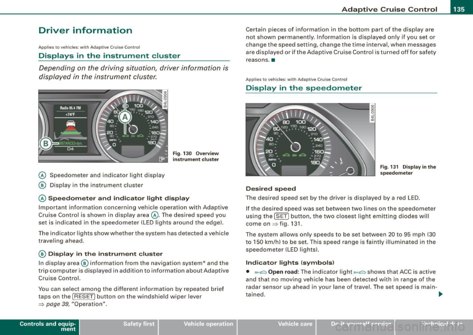
@ Speedometer and indicator light display
@ Display in the instrument cluster
Fig. 13 0 O verv ie w
instrument cluste r
@ Spe edom ete r and indi cat or light display
Important information concerning vehic le operation with Adaptive
Cruise Control is shown in display area @. The desired speed you
set is indicated in the speedometer (LED lights around the edge).
Th e in dicator lights sh ow whe ther the system has detected a vehicle
traveling ahead.
@ Display in the instrument cluster
I n disp lay area @ information from the navigation system* and the
t rip c omputer is disp layed in ad diti on to inf ormation about Adaptive
Cruise Control.
You can select among the differen t info rmation by repea ted brie f
taps on the [R ESET) button on the windshie ld w iper lever
~ page 39, "Operation".
Con tro ls and eq uip
ment
Certain pieces of information in the bottom part of the disp lay are
not shown permanent ly. Information is d isplayed on ly if you se t or
change the speed setting, change the time interval, when messages
are disp layed or if the Adaptive Cruise Control is turned off for safety
reasons .•
A pplies to veh ic les : with Ada ptive Cru is e Cont ro l
Display in the speedometer
Desired speed
Fig . 1 31 D isplay in th e
s pe edome ter
The desired speed set by the drive r is displayed by a red LED .
If the desired speed was set between two lines on the speedometer
using th e [SET) bu tton, the two c losest light emitting diodes will
come on
~ fig . 131 .
The system allows only speeds to be set between 20 to 95 mph (30
t o 150 km/h) to be set. This speed range is faintly illuminated in the
speedometer (LED lights).
Ind icator lights ( symbols )
• ""~ Open road : The indicator light""~ shows that ACC is active
and that no moving vehicle has been detected with in range of the
radar senso r up ahead in your lane of travel. The set speed is main -
t ained . .,
Vehicle care I I Technical data
Page 138 of 398
• ..__A_ d_a...: p:,..._ ti_v _ e_ C_ ru_ is_ e_ C_ o_n_ t_ r_ o _ l ___________________________________________ _
• <0111,c::::, Driv ing in traffi c: The indicator light '°"'''° shows that a
ve hicle moving in your lane of travel has been de tec ted up front in
your lane of travel. Your speed is adjusted according to the speed of
the vehic le up front . ACC accelerates and brakes automatically
within the system's capabilities.
• -011 ,,-0 Dr iv e r intervention prompt : The red flashing warning
light
-011 .. ~ means Request for dri ver to as sume contr ol. You as the
driver must slow the vehic le with the foot brake . The symbol
<0 1111<0
tel ls you that the Adaptive Cruise Control is not able to slow the
vehic le down enough to keep a enough distance to the vehicle in
front of you. A warning tone will also sound when the symbo l
appears . For more information about the driver intervention prompt
::;, page 138.
& WARNING
Improper use of the Adap tive Crui se Contro l features and inatten
tion can lead to an crash and serious personal injury .
• Never allow the closing speed betw een you and other veh icles
to be so high that the Adapt ive Cruise Control may not be able to
slow you r vehi cle saf ely . If clo sing speed is too high , you mu st
apply the brake s yourself to reduce the ri sk of a re ar-end cra sh .
• Always sele ct a greater follo wing dist ance to the vehi cle up
ahead on wet roads than on dry road s.
• Alway s re ad and heed the information and WARNINGS::;,
& in
"De scription " on
pag e 127 .
[ i ] Tips
• If you use the acce lerato r to go faster than the speed of the
vehicle ahead of you, the driver intervention prompt wi ll not be
accompanied by a warning tone.
• If the speed you previously set is exceeded , the indicator light in
the speedometer w ill sw itc h off. •
App lies to vehic les: w ith Ad apt ive Cruise Contro l
Display in the instrument cluster
Fig. 1 32 D isplay i n the
i n strum ent c lust er
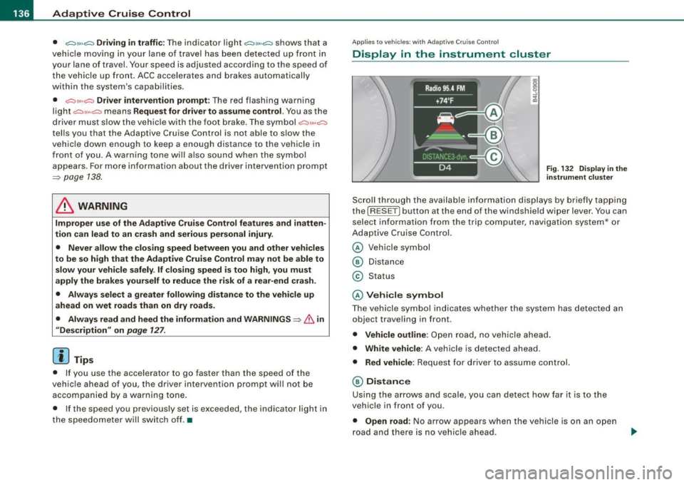
Scroll through the availab le in formati on displays by briefly tapping
the (RESET] button at the end of the windshie ld wiper lever. You can
se lect information from the trip computer, navigation system* or
Adaptive Cruise Control.
© Vehicle symbol
® Distance
© Status
© Vehi cle s ymbol
The vehicle symbo l indicates whether the system has detected an
object traveling in front .
• Vehicle outline : Open road, no vehicle ahead .
• Wh it e v ehi cle: A vehic le is detected ahead.
• Red vehicle: Request for driver to assume co ntrol.
® Distance
Using the arrows and scale, you can detect how far it is to the
vehic le in front of you.
• Open road : No arrow appears when the vehicle is on a n open
road and there is no vehic le ahead .
Page 139 of 398
_____________________________________________ A_ d_a ...: p_ t_ i_ v _e_ C_ ru_ is_ e_ C_ o_n _ t_ r_o _ l _ __._
• Driv in g i n t raff ic: If a vehicle is detected ahead, the arrow moves
on the scale. The green area represents the distance set . When
approaching slowly, the arrow moves from the
gray zone to the
green zone on the sca le .
• Driver int erv ention prompt : When approaching rapidly, the
arrow serves as an early warning signal. If the distance selected is
exceeded or possibly not reached, the arrow moves into the
red
zone on the scale. In certain driving situations, you as the driver wi ll
have to take actio n=>
page 138, "Driver interve ntion prompt" .
© Status
• The text ACC OFF appears in white letters when Adaptive Cru ise
Control is turned off.
• The text
ACC AVAILABLE appears in white letters when the
system is turned on but no desired speed has been set.
• The text
OVERRIDE appears in white letters when you exceed the
desired speed by accelerating .
• The text
DISTANCE ! appears in red letters when the interval to a
vehicle traveling ahead is too sh ort and you have t o slow your
vehicle additionally with the foot brake .
• The tex t messages
DISTANCE 1 to DISTANCE 4 appea r in green
letters to indicate the time interva l you have set and Adaptive Cruise
Control is in management mode .
• I f the driving program "standard" is replaced by "comfort" or
" d ynamic" usi ng the M MI, the above text message is supplemented
by an appropriate prompt, e.g.
DISTANCE 1 -dyn .. •
Con tro ls and eq uip
ment
Ap plies to veh icles: wi th Ada ptive Crui se Co ntro l
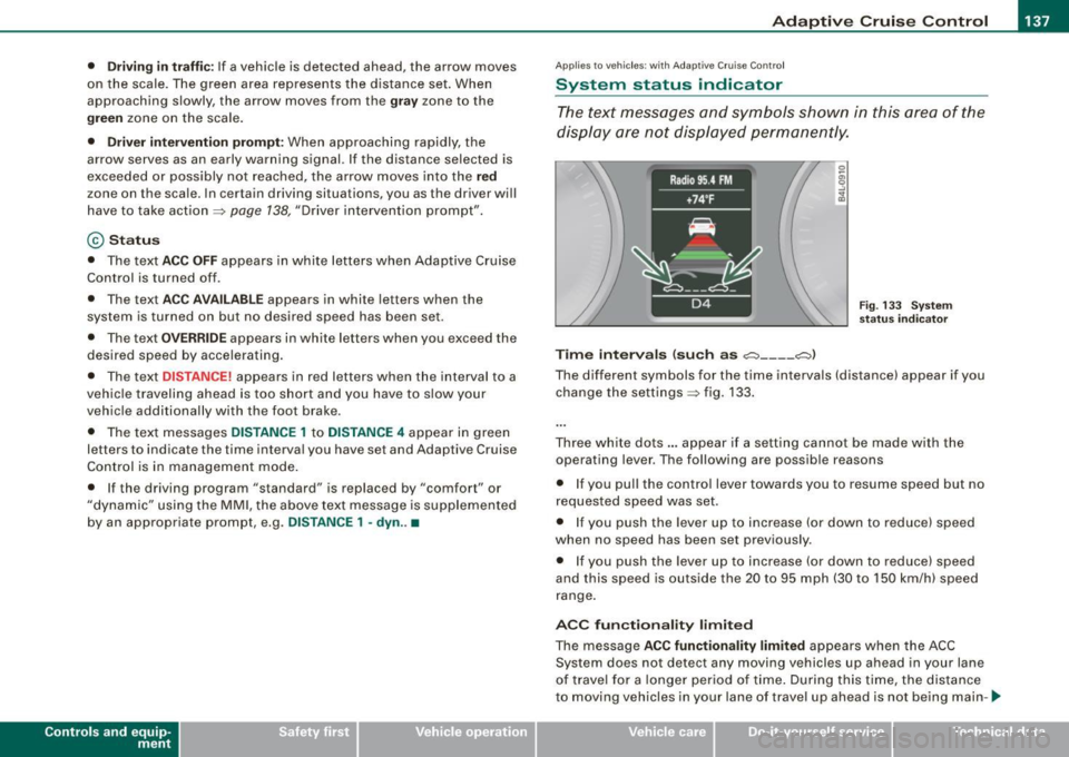
System status indicator
The text messages and symbols shown in this area of the
dis pla y are no t displaye d perm anen tly.
T ime intervals (such as c::::, ___ _ c::::,)
Fig. 133 S ystem
s ta tu s indi cator
The different symbols for the time intervals (distance) appear if you
change the settings=> fig. 133 .
Three wh ite do ts .. . appear if a setting cannot b e made with the
operating lever . The fol lowing are possib le reasons
• I f you pull the control lever towards you t o resume speed but no
requested speed was set.
• I f you push the lever up to increase (or down to reduce) speed
when no speed has been set previously .
• I f you push the lever up to increase (or d own to reduce) speed
and this speed is outside the 20 to 95 mph (30 to 1 50 km/h) speed
range .
ACC fun ction ality limited
The message ACC functionality limited appears when the ACC
System does not detect any moving vehicles up ahead in your lane
of trave l for a lo n ger period o f time . During this time, the dis tance
to moving vehicles in your lane of travel up ahead is not being main-~
Vehicle care I I irechnical data
Page 141 of 398
_____________________________________________ A_ d...;a..! p~ ti_v _ e---- C_ ru_ is_ e ___ C.::..: o;.:.n..:.. t.:.: r...; o:.. 1-----JIIII
In certain situations, the braking power of the Adaptive Cruise
Control is no t enough to maintain an adequate distance to the
vehicle up ahead . In these situations, the Adaptive Cruise Contro l
calls the driver to take action.
The
driv er in tervention pr omp t alerts you visually and audibly to
take over.
• A red vehicle is shown in the instrument c luster display
=>
page 138, fig. 134 .
• The text
DISTANCE! appears in the status line .
• The indicator light~'" '~ in the speedometer b links red.
• A warning tone sounds .
[ i J Tip s
• If the Adaptive cruise control initiates braking, the hydraulic
brake system is under pressure . Therefore, the brake peda l distance
is shorter and the pedal "fee ls" harder .
• Adaptive Cruise Contro l is switched off after pressing the foot
brake. The speed saved up this point can be resumed .
• To resume the saved speed, release the brake pedal and press
the control lever=>
page 132, "Turning Adaptive Cruise Cont ro l off
temporarily" .
• I f you use the accelerator to go faster than the speed of the
vehicle ahead of you, the
drive r inte rv e ntion prompt will not be
accompanied by a warning signal.
• If the speed you previously set is exceeded, the indicator light in
the speedometer wi ll switch off. •
Controls and equip
ment
Ap plies to veh ic les : w ith A dapt ive Crui se Co nt rol
MMI settings
Individual settings for Adap tive Cruise Control can be
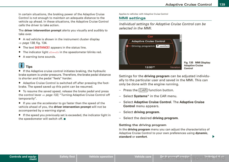
selected in the
MM/ .
Fig. 135 MMI Disp lay :
Ad aptive C ruise
C ontrol
Sett ings fo r th e driving program can be adjusted individu
ally to the p artic ular user and saved in the MML This can
only be do ne with the eng ine r un ning.
Press the
I CAR] fu nction button.
Select
Systems * in the CAR menu .
Select
Adaptive Cruise Control . The Adaptive Cruise
Control
menu appears.
Selec t
driving program.
Select the desired driving program .
Sett ing th e dr iving pr ogram
In the driv ing prog ram menu you can adjust the characteristics of
Adaptive Cruise Contro l to your own preferences using
d ynami c,
s ta nd ard
or comf ort . _.,
I • •
Page 146 of 398
• .___A_ u_ d _ i_l_a _n _ e_ a_ s_s _is _ t _________________________________________________ _
I Not ready: The yellow indicator light shows that the system is
turned on but unable to send a warn ing. This can be due to the
following:
• There are no boundary lines, or there is on ly one boundary line
present .
• The boundary lines are not detected (e.g. due to snow, dirt, wet
conditions or light shining into the camera lens).
• More than two boundary lines (such as at construction sites) are
located in the vehicle's lane.
• The vehicle's speed is below the speed needed to activate it,
which is about 40 mph (65 km/h).
• The lane is narrower than about 8 ft . (2.5 ml, or wider than about
16 ft. (5 ml.
• The curve is too sharp.
Notes on the instrument cluster display
When the lane assist turns off automatically, the instrument cluster
indicator goes out and one of the following messages appears on
the display:
Audi lane assist not available: Currently no sensor vision
This message appears when the camera can no longer function
because it cannot detect the boundary lines. This may be due to the
following :
• The exterior s ide of the camera viewing window=>
page 143,
fig. 144 is covered with dirt or ice. Clean this part of the windshield.
• The camera v iewing window is fogged up on the inside. In this
case, wait until the fog disappears before turning lane assist on
again.
• The system was unable to detect boundary lines over an
extended period of time due to road conditions (such as snow
covered lanes). Do not turn lane assist on again until the lines can
be more easily detected.
Audi lane assist not available
A temporary malfunction is preventing lane assist from operating .
Try turning on lane assist again a t a later time.
Audi lane assist: system fault
The system should be checked by an authorized Audi dealer or other
qualified workshop .
[ i ] Tips
• Make sure that the camera viewing window=> page 143, fig. 144
is not covered by stickers or similar objects .
• Always keep the camera viewing window clean. This can usually
be done by operating the windshield wipers. •
Applies to vehicles: with lane assist
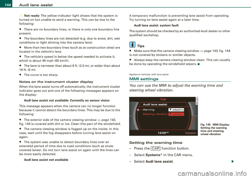
MMI settings
You can use the MM/ to adjust the warning time and
steering wheel vibration.
Setting the warning time
Press the I CAR] function button.
- Select
Systems * in the CAR menu .
- Select
Audi lane assist.
Fig. 145 MMI Display:
Setting the warning
time and stee ring
wheel vibration
Page 154 of 398
1111 Audi side assist
--------------------
G) Sig nal o n outs ide mirr or does no t l ight up
If you activate your turn signal in driving situat ion @, the signal sti ll
does not light up on the outside mirror:::::,
& in "Safety tips" on
page 154. •
Applies to vehic les: with side assist
MMI settings
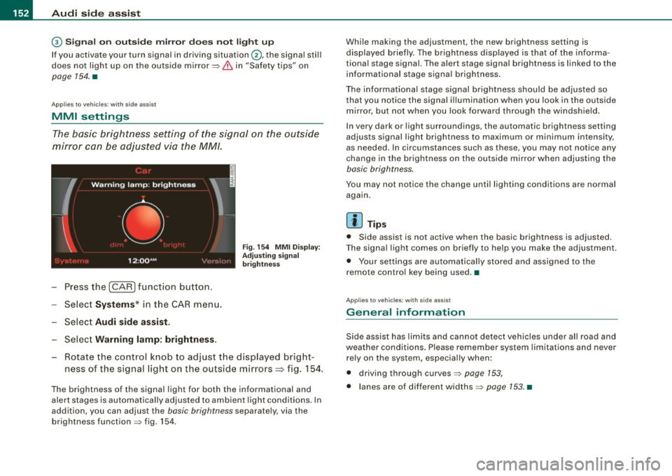
The basic brightness setting of the signal on the outside
mirror can be adjusted via the MM/.
- Press the I CAR I function button.
- Select
Syst ems * in t he CAR menu.
- Selec t
Audi side a ssis t.
Selec t Warning lam p: brightn ess.
Fig. 154 MMI Disp la y:
Adj ust ing s igna l
br ightn ess
Rotate the contro l knob to adjust the displayed bright
ness of the signal light on the outside mirrors~ fig. 154.
The brightness of the signal light for both the informational and
a lert stages is automatica lly adjusted to ambient light cond itions . In
addition, you can adjust the
basic brightness separately, via the
brightness function :::::, fig. 154 . Whi
le making the adjustment, the new brightness setting is
displayed briefly. The brightness disp layed is that of the informa
tiona l stage signal. The alert stage signa l brightness is linked to the
informational stage signal brightness .
The informat iona l stage signal brightness shou ld be adjusted so
that you notice the signal illumination when you look in the outside
m irror, but not when you look forward through the windsh ield .
I n very dark or light surroundings, the automatic brightness setting
adjusts signal light brightness to maximum or minimum intensity,
as needed . In circumstances such as these, you may not notice any
change in the brightness on the outside mirror when adjusting the
basic brightness.
You may not notice the change until lighting conditions are normal
aga in.
[ i ] Tips
• Side assist is not active when the basic brightness is adjusted.
T he signal light comes on briefly to he lp you make the adjustment.
• Your settings are automatically stored and assigned to the
remote contro l key being used .•
Ap plies to vehic les: with side assist
General information
Side assist has lim its and cannot detect vehicles under a ll road and
weather conditions. Please remember system limitations and never
rely on the system, especia lly when:
• driving through curves:::::,
page 153,
• lanes are of different widths:::::, page 153. •
Page 155 of 398
Audi sid e as sis t -
-------------------'
Applies to vehicle s: with side assist
When driving through curves
Side assist canno t detect veh ic les in curves with a turning radius of
less than 328 feet (100 m) .
When driving through a curve, it is possible that side assist may register a vehicle two lanes over, and the signal on the outside
mirror will light up .•
Appl ies t o vehicles: with side ass is t
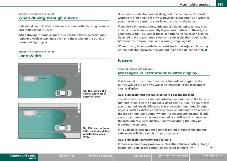
lane width
Con tro ls and eq uip
ment
•
-
-
Fi g. 155 lanes o f a
n ormal width are in
d etec tio n area
Fi g. 156 Nar row lane s:
Si de assis t may detec t
vehi cles tw o l ane s
away
Side assist's detection area is designed to cover lanes of standard
width to the left a nd r ight of your trave l lane, depending on whether
you drive in the center of your lane or c loser to the edge.
I f you drive in narrow lanes, side assist's detection area may also
inc lude other lanes - especially if you tend to drive on the edge of
your lane=> fig. 156. Under these conditions, vehicles can a lso be
detected tha t are two lanes away, a nd s ide assist then could switch
between the informationa l and warning stage signa ls.
When driving in very wide lanes, vehicles in the adjacent lane may
not be detected because they are not inside the detection area .•
Notes
App lies to vehic les : with side assist
Messages in instrument cluster display
If side assist turns off automatically, the indicator light on the
b utton will go out and y ou wi ll see a message in the instrument
cluster disp lay:
Audi side a ssist not avail able : s en sors po ssibly blocked
The side assist sensors are built into the rear bumper on the left and
right (not visible on the outside) =>
page 146, fig. 146. To ensu re that
you do not adversely affect the way side assist functions, foreign
objects (such as stickers o r bicyc le racks) should not be attached to
the area on the rear bumper where the sensors are located . If side
assist functi ons are adversely affec ted, you w ill see this message in
the instrument cluster display. Remove anything that may be
b locking the sensors.
I f no vehic le is detected for a longer pe riod of time while driving ,
side assist will also switch off automatically .
Audi sid e ass is t currently not available
If there is a temporary problem (such as the vehicle's ba ttery cha rge
being low) , side ass ist cannot be activated temporarily . .,_
Vehicle care I I irechnical data
Page 158 of 398
....... __ A_u_ t_o _m_ a_ t_ ic_ t_ r_a _ n_ s_m _ i_s _s _i_o _n ________________________________________________ _
The selector lever must be in Nor P. If one of the driving positions
is engaged a safety switch will prevent the engine from being
started. See also
=:> page 117.
Before you move the selector lever from the
P position, you must
always apply the brake pedal before and while depressing the
button in the handle of the selector lever .
& WARNING
• Unintended vehicle movement can cause serious injury .
- When the selector lever is in a driving position, the vehicle
may creep, even at idle speed . Therefore do not release the
parking brake or foot brake until you are ready to move,
because power is transmitted to the wheels as soon as a
driving position is engaged.
- Do not accelerate while selecting a driving position. At this
time the engine must be at idle speed so that undue stress is
not placed on the clutches in the transmission.
- Remember: -even when stopped briefly with the automatic
transmission in "D", "S" or "R", engine power is being trans
mitted to the wheels. Your vehicle could "creep" forward or
backward. When stopped, keep the brake pedal fully depressed
and use the parking brake if necessary to keep the vehicle from
rolling.
• If the selector lever is unintentionally moved into N while you
are driving, take your foot off the accelerator pedal and wait for
the engine to return to idle speed before selecting a driving posi
tion .
• Never shift into "R" or "P" when the vehicle is in motion.
• Never get out of the driver's seat when the engine is running .
• If you must get out of the vehicle, move the selector lever
securely into the P position and apply the parking brake firmly.
• If the engine must remain running , never have any driving posi
tion engaged when checking under the hood. Make sure the
selector lever has securely engaged and is locked in "P" with the
& WARNING (continued)
parking brake firmly set=> page 293, "Engine compartment".
Otherwise, any increase in engine speed may set the vehicle in
motion, even with the parking brake applied. •
App lies to vehicles: with 6-speed automatic t ransmission
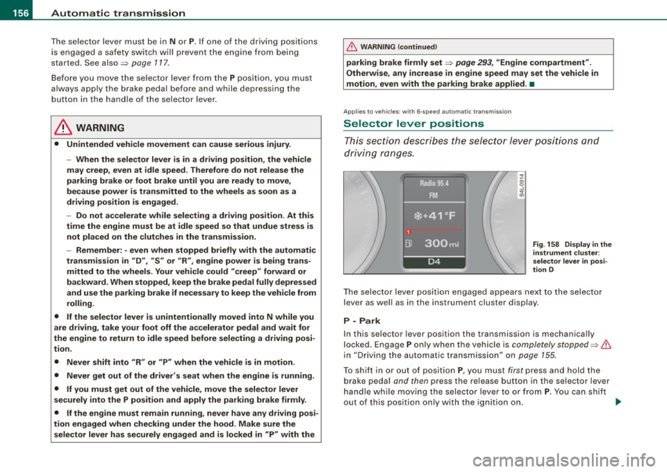
Selector lever positions
This section describes the selector lever positions and
driving ranges.
Fig . 158 Display in the
instrument cluster:
selector lever in posi
tion D
The selector lever position engaged appears next to the selector
lever as well as in the instrument cluster display .
P -Park
In this selector lever position the transmission is mechanically
locked. Engage
P only when the vehicle is completely stopped=> &
in "Driving the automatic transmission" on page 155.
To shift in or out of position
P, you must first press and hold the
brake pedal and then press the release button in the selector lever
handle while moving the selector lever to or from
P. You can shift
out of this position only with the ignition on.
~
Page 160 of 398
_L-_:..A.:.u:::..: t.:o :..m.:..:.; a:::..: t:.. ic:....: t:.:. r..:a :.. n...:..:: s.:.m _;_:.:, i..::s ..:s :.:.i..:o :..n_;_ _______________________________________________ _
-Step on the brake peda l. At the same time press and hold
the interl ock butto n on t he side of the gear selector kn ob
:::::, fig . 159 with you r thumb until you have moved the
se lector lever to the desired pos ition.
Automatic selec tor lever lo ck
The selector lever is locked in the P and N positions when the igni
tion is turned on. To move the leve r from these positions the driver
must depress the brake peda l. As a reminder to the dr iver , the
following warn ing app ears in the instrument c luster display when
t h e selector is in
P and N :
When station ary apply fo otbr ake while sele cting ge ar
A time de lay e lement prevents the se lector lever from lock ing when
it is moved through the
N position (going from R to Dl. The locking
e lement will lock the selector lever if the l eve r is l eft in N (Neutral)
for more than approximately 1 second , without the brake pedal
being pressed.
At speeds above ab out 3 mph (5 km/h) the Automatic Shift Lock is
automatically deac tivated in the
N position .
Interlo ck button
The lock bu tton on the s elector lever prev ents the lever from being
accidentally shifted into certain positions . Press ing this bu tton
deac tivates the selec tor lever lock . Depending on the dir ection of
t he shift, the se lector lever locks at diffe rent positions . The positions
are highlighted in the illustration~
page 157, fig. 159 .
Ignition key safet y interlock
The k ey cannot be remov ed from the igni tion un less the selector
lever is in the
P park p osition. When the ign ition key is removed, the
selector lever wil l be locked in the
P position. •
Applies to vehicles: w it h 6 -spee d au tomat ic tra nsm ission
Kick-down
The kick-down feature allows the vehicle to generate
maximum acceler ation.
When you press the accelerator pedal beyond the resistance po int
that is reached at fu ll thrott le, the transmission will se lect a lower
gear rat io based on vehicle speed and engine RPM . The engine RPM
wi ll be contro lled to produce max imum vehicle acceleration as long
as you continue to press the accelerator pedal beyond this resis
tance point .
& WARNING
Be careful when u sing the kick-down feature on slippery road s.
Rapid ac celerat ion may cause the veh icle to skid. •
Applies to veh icles : wit h 6-s p ee d au to m ati c tra nsmiss ion
Dynamic shift program (DSP)
The aut om atic tr a nsmission is electronically controlled.
T he transmission is self adapting and wi ll automati cally se lect the
b est shift program suited to the driving condi tions and drivi ng s tyle.
The transmission wil l se lect one of the
e conom y programs when
you drive at a steady speed or a gradually changing speed withou t
heavy acceleration . This achieves optimum fuel efficiency, with early
upshifting and delayed downshifting.
The trans mission wil l au tomat ical ly select the
sporty shift programs
when you drive at higher speeds, or with heavy acce leration and
frequently changing speeds . Upshifts ar e delayed to make full use
of engine power . Down shifting takes place at higher engine speeds
t han in the economy programs . _.,
Page 161 of 398
_________________________________________________ A_ u_t_ o_ m_ a_t _i _ c _ t _ra_ n_s_ m __ is_ s_ io_ n _ __.1!111
The selection of the most suitable shift program is a continuous,
automatic process. The driver can also make the transmission
switch to a sporty program by
q u ickly pressing down the gas pedal.
This causes the transmission to shift down to a lower gear to achieve rapid acceleration, e.g. for quickly passing another vehicle.
You do not need to press the gas pedal into the kick -down range .
After the transmission has upshifted, the orig inal program is
selected according to your driving style.
An additional shift program allows the automatic transmission to select the proper gear for uphill and downhill gradients .
This keeps the transmission from shifting up and down unneces
sarily on hills. The transmission will shift down to a lower gear when
the driver presses the brake pedal on a downhill gradient. This
makes use of the braking effect of the engine without the need to
shift down manually .•
Ap plies to ve hic les: wit h 6-spee d automat ic t ransm iss ion
Manual shift program
Using the manual shift program you can manually select
gears .
Contro ls and eq uip
ment
Fig . 160 Ce nter
co nso le: sh ifting the
ti ptro n ic® man ua lly F
ig . 161 Display:
m an ua l shift progr am,
selecte d gear
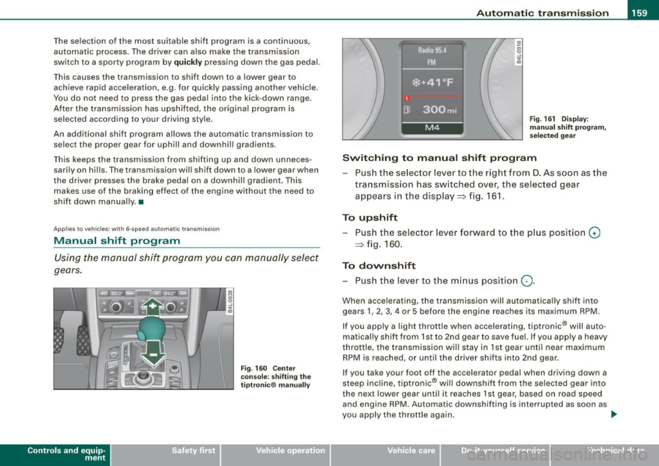
Swit ching to manu al s hift progr am
Push the selector lever to the r ight from D . As soon as the
transmission has switched over, the selected gear
appears in the display=> fig . 161.
To upshift Push the selector lever forward to the p lus posit ion
G)
=> fig. 160 .
To down shift
- P ush the lever to the min us positio n
Q.
When accelerating, the transmission will automatica lly shift into
gears 1, 2, 3, 4 or 5 before the engine reaches its maximum RPM.
If you app ly a light throttle when accelerating, tiptronic ® will auto
matical ly shift from 1st to 2nd gear to save fuel. If you apply a heavy
throttle, the transmission w ill stay in 1st gear until near maximum
RPM is reached , or until the driver shifts into 2nd gear .
If you take your foot off the accelerator peda l when driving down a
steep inc line, tiptronic ® will downshi ft from the selected gear into
the next lower gear until it reaches 1st gear, based on road speed
and engine RPM. Automatic downshifting is interrupted as soon as
you apply the throttle again.
~
Vehicle care I I Technical data