instrument cluster AUDI S6 2015 Owners Manual
[x] Cancel search | Manufacturer: AUDI, Model Year: 2015, Model line: S6, Model: AUDI S6 2015Pages: 314, PDF Size: 77.57 MB
Page 11 of 314
M N
0 <.J 'SI: ,...., \!) 1.1'1 ,...., 1.1'1 ,....,
CD
@
®
©
®
®
(j)
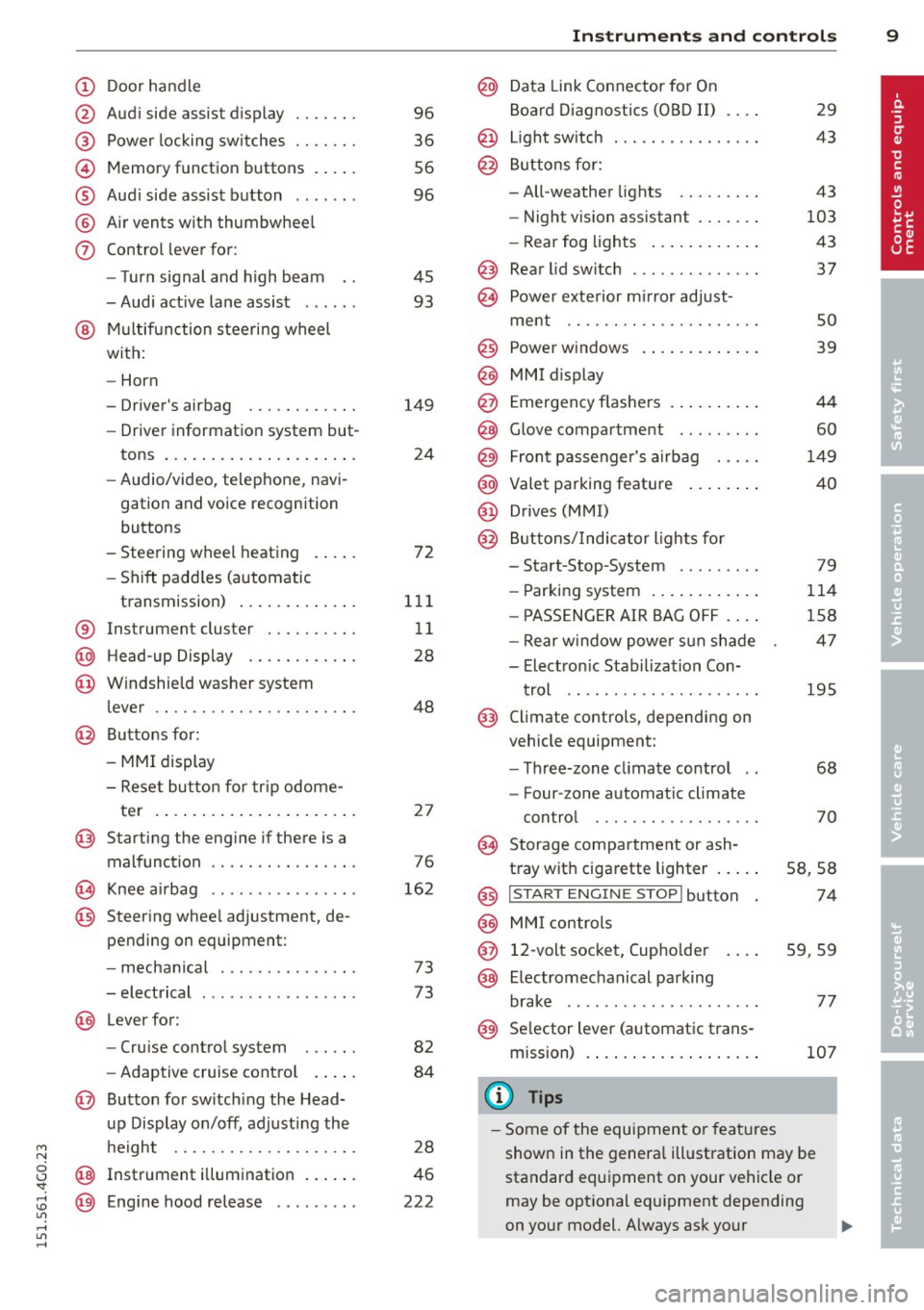
Door handle
Audi side assist d isplay
Power locking sw itches
Memory function buttons . ... .
Aud i side assist button .. .. .. .
A ir vents with thumbwheel
Control lever for :
- T urn signal and high beam
- Audi act ive lane assist . .. .. .
@ Mu ltifunction steering wheel
with:
- Horn
- Driver's airbag
- Driver information system but-
tons ... .... ........ ... .. .
- Audio/video , telephone, navi
gation and voice recognition
buttons
- Steering wheel heating . ... .
- Shift padd les (automatic
transmission) ..... ... .. .. .
® Instrument cluster ..... .. .. .
@ H ead-up Display ....... .. .. .
@ Windshie ld washer system
lever .. .. ............. .... .
@ Buttons for :
- MMI display
- Reset bu tton for tr ip odome-
te r .. .. ... .. ..... ... .. .. .
@ Starting the eng ine if there is a
malfunction .............. . .
~ Knee ai rbag ........... .. .. .
@ Steer ing whee l adjustment, de
pending on equipment:
- mecha nical .......... .. .. .
- electrical .... .. ...... .. .. .
@ Leve r for:
- Cru ise control system . .. .. .
- Adaptive cruise contro l .. .. .
@ Button for sw itch ing the Head
up Disp lay on/off, adjusting the
h eight .. ............. .. .. .
@ Instrument illum ination ... .. .
@ Eng ine hood re lease ....... . . 96
36
56
96
45 93
149 24
72
111 11
28
48
2 7
76
16 2
73
73
82
84
28
46
222
In strument s and control s 9
@ Data Link Connector for On
Board Diagnostics (OBD II)
@ Light sw itch ... .. . .. .... ... .
@ B uttons for :
- All-weather lights
- Night vision assistant .... .. .
- Rear fog lights .. .. .. ..... .
@ Rear lid switc h ............. .
~ Power exte rior m irror adjust- 29
43
43
103 43
37
ment . . . . . . . . . . . . . . . . . . . . . 50
@ Power w indows . . . . . . . . . . . . . 39
@ MMI display
@ Emergency flashe rs . . . . . . . . . . 44
@ Glove compartment . . . . . . . . . 60
@) Front passenger's airbag . . . . . 149
@ Valet parking feature . . . . . . . . 40
@ Drives (MMI)
@ Buttons/Indicator ligh ts fo r
- Start-Stop-System . . . . . . . . . 79
- Parking system . . . . . . . . . . . . 114
- P ASSENG ER AIR BAG OF F . . . . 1S8
- Rear w indow powe r sun shade 47
- Electron ic Stabilization Con-
t rol . . . . . . . . . . . . . . . . . . . . . 19S
@ Climate controls, depending on
vehicle equipment:
- Three-zone cl imate control . . 68
- F our-zone automat ic climate
cont rol . . . . . . . . . . . . . . . . . . 70
@ Storage compartment or ash-
t ray wit h cigarette lighter . . . . . S8, 58
@ I S T ART ENGINE STOPI button 74
@ MM I controls
@ 12-volt socket, (upho lder 59, 59
@ E lectromechanical parking
brake . . . . . . . . . . . . . . . . . . . . . 77
@ Selector lever (a utomatic trans-
mission) 107
(D Tips
-Some of the equipment or fea tures
show n in the genera l ill ustration may be
standard equipment on your vehicle or
may be opt ional eq uipment depending
on your model. Always ask your
ll>
Page 13 of 314
M N
0 I.J -
"' rl
Instrument s and warning /indicator lights 11
Instruments and warning/indicator lights
Instruments
Instrument cluster and controls
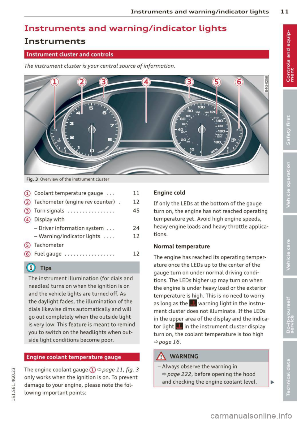
The instrument cluster is your central source of information.
Fig. 3 Overv iew of the instrument cluster
CD Coolant temperature gauge .. .
@ Tachometer (eng ine rev counter)
@ Turn signals ............... .
@ Display with
®
®
-Driver information system .. .
- Wa rning/ind icator lights
Tachometer Fuel gauge
@ Tips
11
12
45
24
12
12
The instrument illumination (for dials and
needles) turns on when the ignition is on
and the vehicle lights are turned off. As
the daylight fades, the illumination of the
dials likewise dims automatically and wil l
go out completely when the outside light
is very low. This feature is meant to rem ind
you to switch on the headlights when out
side light conditions become poor.
Engine coolant temperature gauge
The engine coolant gauge CD¢ page 11, fig. 3
only works when the ignition is on. To prevent
damage to your eng ine, please note the fol
l owing important points:
Engine cold
If only the LEDs at the bottom of the gauge
turn on, the eng ine has not reached operating
temperature yet . Avoid high engine speeds,
heavy engine loads and heavy throttle applica
tions.
Normal temperature
The engine has reached its operating temper
ature once the LEDs up to the center of the
gauge turn on under normal driving cond i
t ions. The LEDs higher up may turn on when
the engine is under heavy load or the exterior
temperature is high. This is no need to worry
as long as the. warning light in the instru
ment cluster does not illuminate . If the LEDs
in the upper area of the display and the indica
tor light . in the instrument cluster display
turn on, the coolant temperature is too high
¢page 16.
A WARNING
-Always observe the warn ing in
¢ page 222, before opening the hood
and checking the engine coolant level.
Page 14 of 314
12 Instrum ent s and w arn ing /indic ato r light s
-Never open the engine hood if you see or
hear steam, or if you see engine coolant
dripping from the engine compartment.
You could burn yourself . Let the engine
cool off first until you can no longer see
o r hear steam or coo lant escaping.
@ Note
- Mounting additional lights or accessories
i n front of the a ir inlets reduces the cool
i ng effect of the rad iator . At h igh outside
temperatures or high eng ine load, the
engine could overheat.
- The front spo iler has been designed to
proper ly distribute the cooling air when
t h e ve hicle is moving.
If the spoiler is
dam aged, th is co uld red uce the cooling
effect and the engine co uld then over
heat . Ask your authorized Audi dea ler for
assistance .
Tachometer (engine rev counter)
The tachometer indicates the engine RPM
(revolutions per minutes).
If engine RP M drops be low 1,500, yo u should
downshift to the next lower gear. The red a rea
at the end of the sca le indicates maximum
perm iss ib le engine RPM after the break-in pe
riod. Before reaching this area, move these
lector lever to position D/S (Drive) or ease
your foot off the accelerator pedal.
(D Note
The tachometer needle should on ly br iefly
be in the red zone: you could damage your
engine! The beginn ing of the red zone var
ies depending on the engine .
@ For the sake of the environment
Upshifting early saves fuel and reduces en
gine noise.
Fuel gauge
The fuel gauge only works when the ignition is
on .
If the fuel level d rops below 2 . 6 ga llons (10 liters), the bottom LED turns red and the
indicator light
ll'J turns on r=> page 22. The
bottom LED blinks red when the fuel level is
very low.
T he possible range based on the current fuel
level is shown in tab@r=>
page 24, fig . 4 .
(D Note
Never run the tank completely dry. An ir
r egular supply of f uel can cause engine
misfiring and fuel could enter the ex ha ust
system . The catalytic converter could then
overheat and be damaged.
Warning/indicator Lights
Description
The ind icator lights in the instrument cluster
blink or turn on. They indicate funct ions or
malfunctions
r::!> ,& .
Messages may appear with some indicato r
lights. A warning signal will sound at the
same t ime. The indicator lights and messages
in the center of the displays may be rep laced
by other d isplays . To show them again, select
the tab for ind icator lights and messages us
i ng the multifunction steering wheel
r::!> page 24. If t here are several malfunc
t ions, you can display them one at a time us
ing the thumbwheel.
Some indicato rs lights in the d isplay can turn
on in severa l co lors.
A WARNING
- F ailure to heed w arning l igh ts and other
important vehicle in forma tion may res ult
in ser io us personal inj ury or vehicle dam
age .
- Whenever stalled or stopped for repair, move the vehicle a safe d istance off the
road, stop the engine, and turn on the
emergency flasher
r::!> page 44.
- The engine compartment of any motor
veh icle is a potentially hazardous area.
Before you chec k anything in the engine
Page 21 of 314
M N
0 <.J 'SI: ,...., \!) ..,.,
,...., ..,., ,....,
Instrument s and warnin g/indic ator ligh ts 19
~/ !J.: Safety systems
The fl (USA models)/ E,I (Canada mode ls) in
d icator light moni tors the safety systems (e.g.
airbags, pretensioners) and illuminates for a
few seconds each time you switch the ignition
on.
If the II (USA mode ls)/ E,I (Canada models)
indicator light does not go out, or if it illumi
nates while you are driving, or if it starts to
blink, then there is a ma lfunction somewhere
in the system.
If the light does not illuminate
when you switch the ignition on, this also means there is a malfunction.
A WARNING
If you have a malfunction in the safety sys
tems, contact your author ized Audi dealer
immediately. Otherw ise the safety sys
tems may not wo rk p roperly in an acci
dent.
& Central indicator light
I f the indicator light . or II turns on, check
the message in the instrument cluster.
f;.J ~ Electronic Stabilization Control
(ESC)
If the J.i3 indicator light blinks wh ile driving,
the ESC or ASR (Ant i-Slip Regulation) is active
ly regulating .
If the
G1 indicator light turns on, the system
has sw itched the ESC off. In this case, you can
switch the ignition off and then on to switch
the ESC on again. The indicator light turns off
when the system is functioning fully.
If the
fl indicator light turns on, ESC was re
stricted using the
I ~ OF FI button¢ page 193 .
Stabilization cont rol (E SC /AB S): F ault! See
owner 's manu al
If the DJ indicator light and the ABS indicator
light
f;U1 (USA models) 1 11] (Canada mode ls)
turn on and the message appears, the ABS or
electronic differential lock is ma lfunction ing .
This a lso causes the ESC to malfunct ion. The brakes still function with their normal power,
but ABS is not active.
D
rive to your author ized A udi dealer or quali
f ied wor kshop immed iate ly to have the mal
f unct ion corrected .
A WARNING
If the . (USA mode ls)/ . (Canada mod
e ls) brake system indicator light turns on
together with the ABS and ESC indicator
lights, the ABS/ESC regulating function
may have fa iled. Functions that stabilize
the vehicle are no longe r available. Th is
could cause the vehicle to swerve and in
crease the risk of sliding. Drive ca refully to
the nea rest authori zed Audi dealer or oth
e r qualified workshop and have the ma l
f u nction corrected.
(D Tips
For additional informat ion on ESC and
ABS, refer to
¢page 193.
ABS/(8) Anti-lock braking system (ABS)
This warning/indicator light monitors the ABS
and the elec tronic differential lock (EDL).
The wa rning/indicator light f;U1 (USA mod-
els)
I ii] (Canada models) w ill com e on for a
few seconds whe n the ignition is switched on.
T he light will go o ut after an automa tic check
sequence is comp leted .
There is a malfunct ion in the ABS when:
- The warn ing/indicator light does not illum i
nate when you switch the ign it ion on.
- The warn ing/indicato r light does not go out
after a few seconds.
- The warning/indicator light illum inates
while driving.
The ESC indicator lig ht also illuminates if
there is a malfunction in the ABS. The mes
sage
S tab ilizat ion control (ESC /ABS ): Fault!
S ee owner's manual
also appears in the i n
strument cluster d isp lay and a warning tone
sounds.
~
Page 22 of 314
20 Instruments and warning/indicator lights
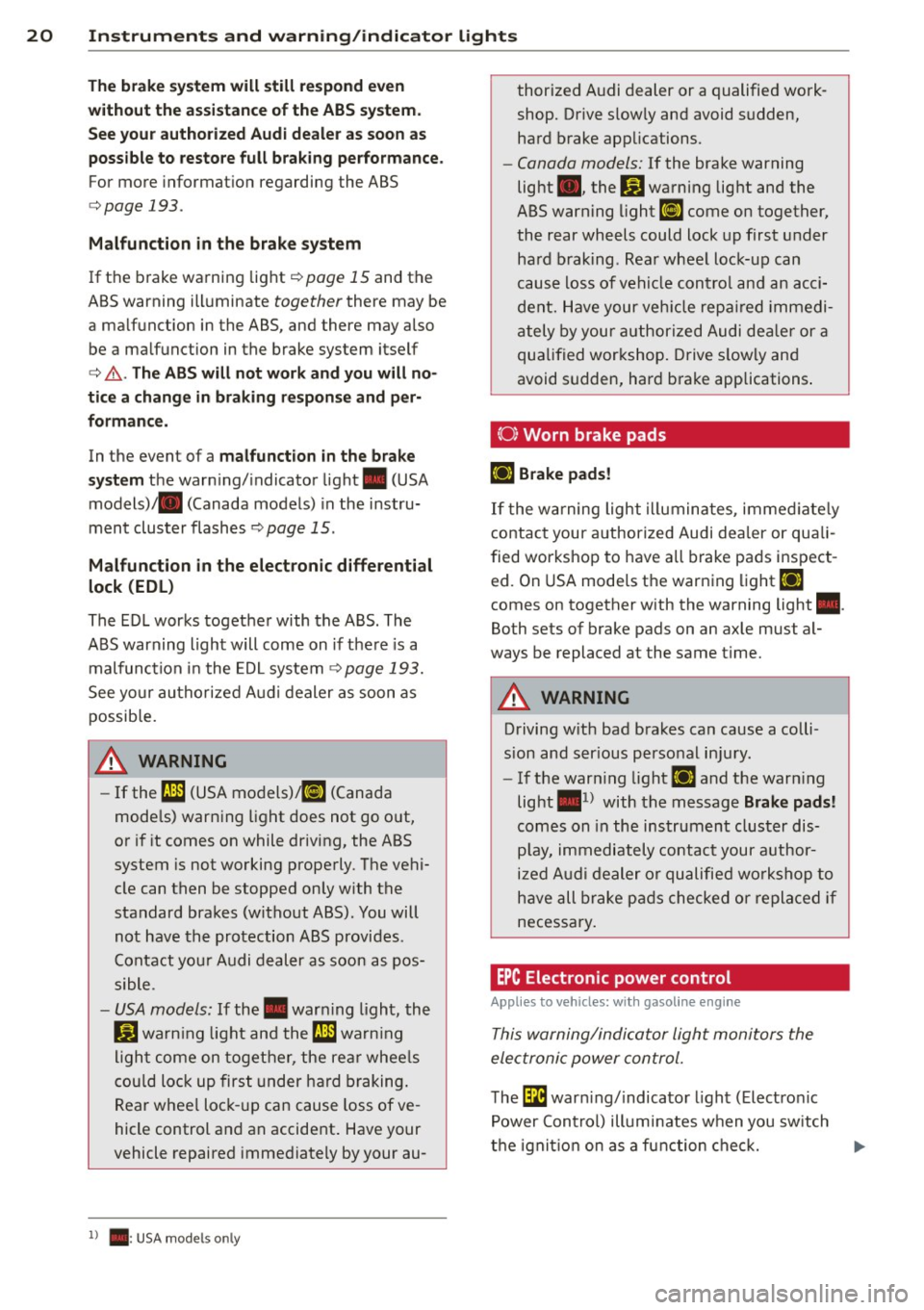
The brake system will still respond even
without the assistance of the ABS system.
See your authorized Audi dealer as soon as
possible to restore full braking performance.
For more information regarding the ABS
c;,page 193.
Malfunction in the brake system
If the brake warning light c;,page 15 and the
ABS warning illuminate
together there may be
a malfunction in the ABS, and there may also be a malfunction in the brake system itself
c;, &. . The ABS will not work and you will no
tice a change in braking response and per
formance.
In the event of a malfunction in the brake
system
the warning/indicator light . (USA
models)/ . (Canada models) in the instru
ment cluster flashes ¢
page 15.
Malfunction in the electronic differential
lock (EDL)
The EDL works together with the ABS. The
ABS warning light will come on if there is a
malfunction in the EDL system¢
page 193.
See your authorized Audi dealer as soon as
possible.
A WARNING
- If the f;t11 (USA models);tlJ (Canada
models) warning light does not go out,
or if it comes on while driving, the ABS
system is not working properly. The vehi
cle can then be stopped only with the
standard brakes (without ABS). You will
not have the protection ABS provides .
Contact your Audi dealer as soon as pos
sible.
- USA models: If the . warning light, the
fjJ warning light and the f;t11 warning
light come on together, the rear wheels
could lock up first under hard braking.
Rear wheel lock-up can cause loss of ve
hicle control and an accident. Have your
vehicle repaired immediately by your au-
l ) . : USA mode ls o nly
thorized Audi dealer or a qualified work
shop. Drive slowly and avoid sudden,
hard brake applications.
- Canada models: If the brake warning
light ., the
B.1 warning light and the
ABS warning light
ti] come on together,
the rear wheels could lock up first under
hard braking. Rear wheel lock-up can
cause loss of vehicle control and an acci
dent. Have your vehicle repaired immedi
ately by your authorized Audi dealer or a
qualified workshop. Drive slowly and
avoid sudden, hard brake applications.
(0} Worn brake pads
Ill Brake pads!
If the warning light illuminates, immediately
contact your authorized Audi dealer or quali
fied workshop to have all brake pads inspect
ed. On USA models the warning light
Ill
comes on together with the warning light •.
Both sets of brake pads on an axle must al
ways be replaced at the same time.
A WARNING
Driving with bad brakes can cause a colli
sion and serious personal injury.
- If the warning light
Ill and the warning
light •
1
) with the message Brake pads!
comes on in the instrument cluster dis
play, immediately contact your author
ized Audi dealer or qualified workshop to
have all brake pads checked or replaced if
necessary.
EPC Electronic power control
Applies to veh icles: w ith gasoline engine
This warning/indicator light monitors the
electronic power control.
The l3i warning/indicator light (Electronic
Power Control) illuminates when you switch
-
the ignition on as a function check. ..,.
Page 26 of 314
24 Instruments and warning/indicator lights
Driver information
display
Overview
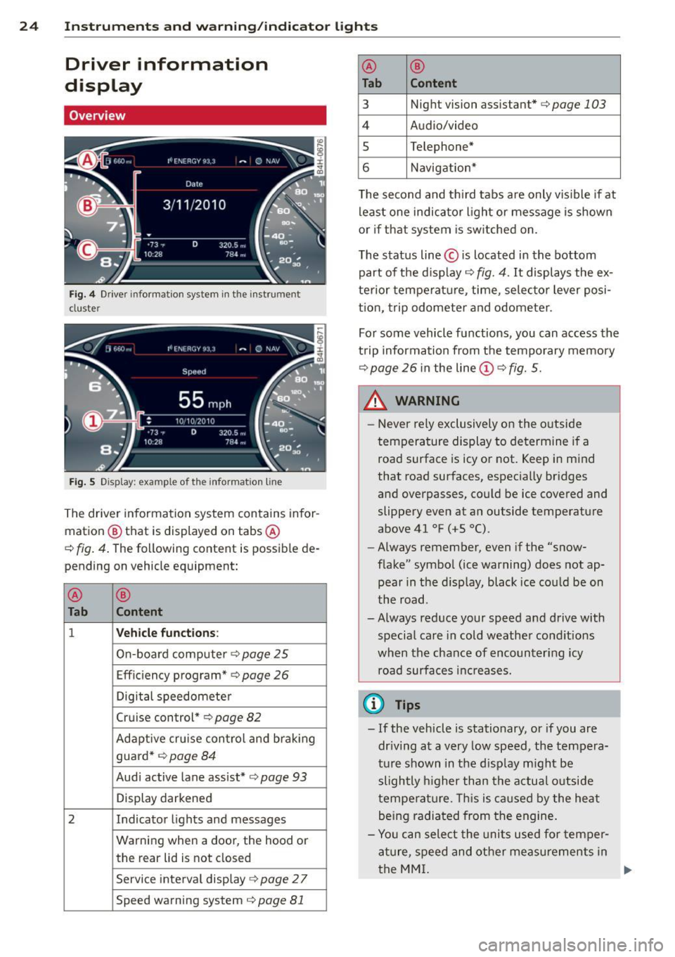
Fig. 4 Driver information system in the instrument
cluster
Fig. S Display: example of th e information line
The driver information system contains infor
mation @ that is displayed on tabs @
c:;, fig. 4. The following content is possible de
pending on vehicle equipment:
@
®
Tab Content
1 Vehicle functions :
On-board computer c::> page 25
Efficiency program* c::> page 26
Digital speedometer
Cruise control*
c;, page 82
Adaptive cru ise con trol and braking
guard*
r::;, page 84
Audi active lane assist* c;, page 93
Display darkened
2 Indicator lights and messages
Warning when a door, the hood or the rear lid is not closed
Service interval display
c::> page 2 7
Speed warning system c;, page 81
@ ®
Tab Content
3 Night vision assistant* c;, page 103
4 Audio/video
s Telephone*
6 Navigation*
T he second and th ird tabs are only vis ible if at
least one indicator light or message is shown
or if that system is sw itched on.
The status line © is located in the bottom
part of the display
c::> fig. 4. It displays the ex
terior temperature , time, selector lever posi
t ion, trip odometer and odometer.
For some vehicle functions, you can access the
trip information from the temporary memory
c::> page 26 in the line (D c::> fig. 5.
_& WARNING
= -
- Never rely exclusively on the outside
temperature display to determine if a
road surface is icy or not. Keep in mind
that road surfaces, especially bridges
and overpasses, could be ice covered and
slippery even at an outside temperature
above 41 °F
(+5 °().
-Always remember, even if the "snow
flake" symbol (ice warning) does not ap
pear in the d isplay, black ice could be on
the road.
- Always reduce your speed and drive with special care in cold weather cond itions
when the chance of encountering icy
road surfaces increases.
(D Tips
-If the vehicle is stationary, or if you are
dr iving at a very low speed, the tempera
ture shown in the d isplay m ight be
slightly higher than the actual outside
temperature . Thi s is caused by the heat
being radiated from the engine.
- Yo u can select the units used for temper
ature, speed and other measurements in
the MMI.
IJ,-
Page 27 of 314
M N
0 I.J "". rl I.O
"' rl
"' rl
Instrument s and warning /indicator lights 25
- For in formation on the a udio/video and
navigation * functions, refer to the se pa
r ate
M MI owner's manual.
Operation
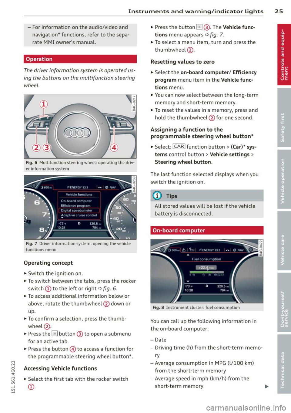
The driver information system is operated us
ing the buttons on the multifunction steering
wheel.
Fi g. 6 Mult ifu nct io n stee ring wheel: operat ing t he dr iv
er informat ion system
F ig. 7 Driver informat ion system: open ing t he ve hicle
funct ions men u
Operating concept
• Switch the ign ition on.
• To sw itch between the tabs, p ress the rocker
switch
(D to the left or right c> fig . 6 .
• To access addi tional in format io n be low or
above, rotat e th e thumbw heel @dow n or
u p.
• To c onfirm a sele ction, press t he thumb
whee l@ .
• Press the~ button @to open a submen u
for an active tab .
• Press the button
© to access a function for
the programmable steering w heel b utton*.
Acce ss ing Vehicle functions
• Se lect the f irst tab w ith the rocker sw itch
(D .
• Press the button ~@-T he Vehicle func
tions
men u appears c> fig. 7.
• To se lect a menu item, turn and press t he
thumbwhee l@ .
Resetting values to zero
• Sele ct the on-board computer / Efficiency
program
men u item in the Vehicle func
tions
men u .
... Yo u can now select between the long-term
memory and s hort -term memory .
.,. To reset the values in a memory, p ress and
hold t he thumbwheel @for one second.
Assigning a funct ion t o the
programmable steering wheel button*
• Select: !CAR ! function button> (Car)* sys
tems
control button > Vehicle settings >
Steering wheel button .
The last functi on selected disp lays when you
switch the ig nition on .
('!) Tips
All stored va lues w ill be lost if the veh icle
battery is disconnecte d.
On-board computer
Fig. 8 In strume nt cluster : fuel consump tion
You can ca ll u p t he following information in
the on-board computer:
- Date
- Dr iving t ime (h) from the sho rt-term memo-
ry
- Average consumption in MPG ( l/100 km)
from the short-term memory
- Average speed i n mph (km/h) from the
short-te rm memory
Page 29 of 314
M N
0 I.J "". rl I.O
"' rl
"' rl
Instrument s and warning /indicator lights 2 7
Fuel economy messages
Fuel economy messages are disp layed when
fuel consumption is increased by certain con
ditions ~
fig. 10 . If you follow these fuel
economy messages, you can reduce your vehi
cle's consumption of fuel. The messages ap
pear automatically and are only displayed in
the efficiency program. The fuel economy messages turn off automatically after a cer
tain period of time .
To turn an economy message off immediately after it appears, press any button on the mul
tifunction steering wheel.
@ Tips
- If the data are deleted in the efficiency
program, those values are also reset in
trip computer .
- Once you have turned a fuel economy
message off, it will only appear again af
ter you turn the ignition on aga in .
- The fuel economy messages are not dis
played in every instance, but rather in in
tervals over a period of ti me .
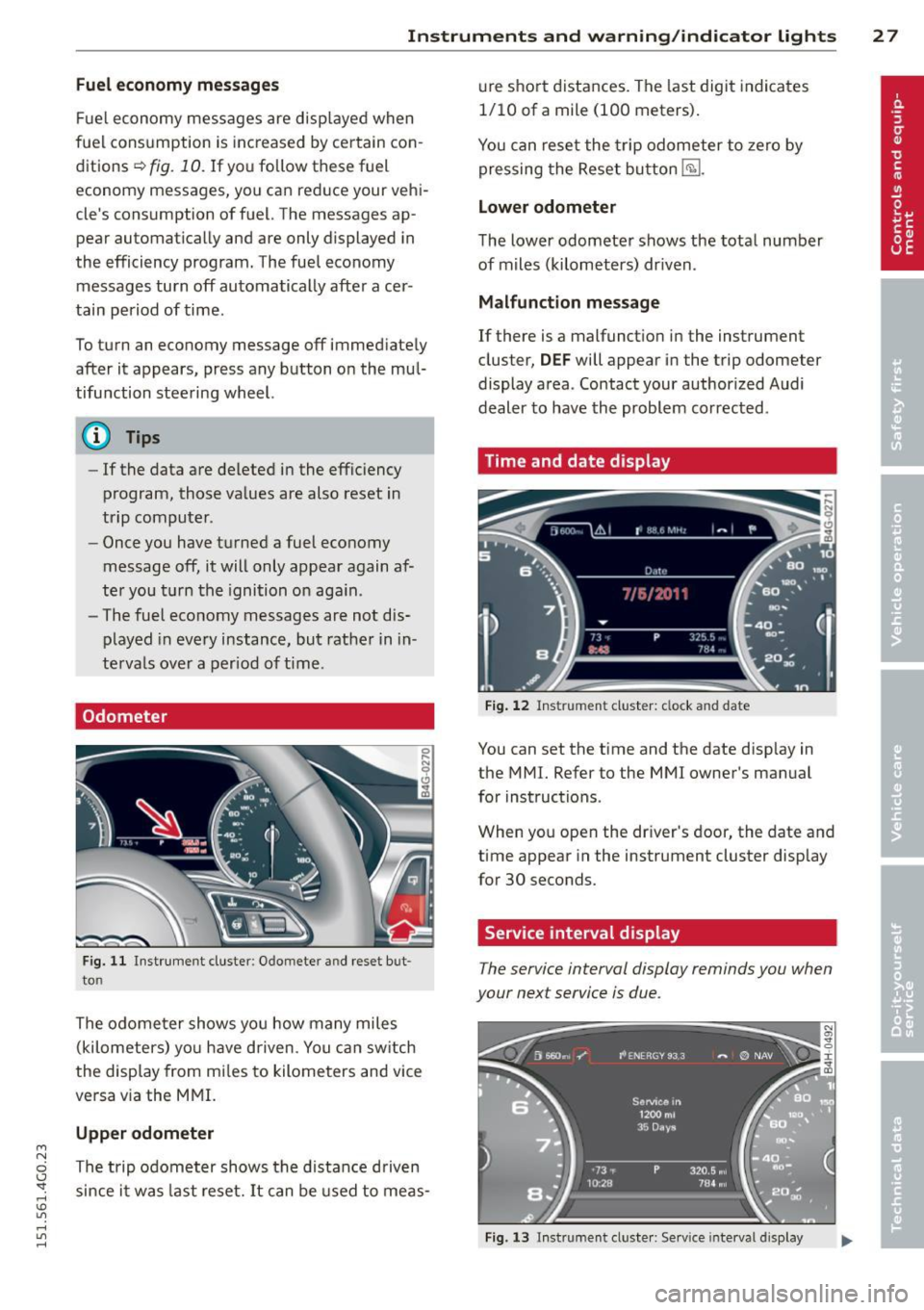
Odometer
Fig. 11 Instrument cluster: O domete r an d rese t but
to n
The odome ter shows you how many miles
(kilometers) yo u have d riven . You can switch
the display from mi les to kilometers and vice
versa via the MMI.
Upper odometer
The trip odometer shows the distance driven since it was last reset. It can be used to meas- ure
short distances. The last digit indicates
1/10 of a mile (100 meters).
You can reset the trip odometer to zero by
pressing the Reset button
E§l.
Lower odometer
The lower odometer shows the total number
of miles (kilometers) dr iven .
Malfunction message
If there is a malfunct ion in the instrument
cluster,
DEF will appear in the trip odometer
display area . Contact your authorized Audi
dealer to have the problem corrected .
Time and date display
Fig. 12 Instrume nt cluster: clock and date
You can set the time and the date disp lay in
the MMI. Refer to the MMI owner's manual
for instructions .
When you open the dr iver's door, the date and
time appear in the instrument cluster display
for 30 seconds.
Service interval display
T he service interval display reminds you when
your next service is due .
Fig. 13 Instrumen t cl uster: Serv ice interva l display
Page 31 of 314
M N
0 I.J "". rl I.O
"' rl
"' rl
Instrument s and warning /indicator lights 29
Adjusting the height
The height of the display can be a djus ted to
t he individual driver .
.. Make sure you a re seated cor rect ly
<=>page 127.
.. Turn the knob~ to adjust the displ ay .
Settings in the MMI
.. Se lect: I CARI funct ion button > ( Car )* s ys
tems
control button > D river Assist > Head
up Display > Head-up Display content
or
Di splay brightne ss .
Display content
In the MMI, you ca n specify which information
should be displayed :
- Cruise contro l system*
- Navigatio n information*
- A udi adaptive cruise control *
- Audi a ct ive lane assist*
- Night vis ion assistant*
The speed display and some of the red indica tor lights cannot be hidden in the MMI.
Display brightness
You can ad just the display brightness in t he
MMI. The display brightness decreases auto
mat ica lly as the amount of light decreases.
The basic leve l of brightness is adjusted with
the ins trumen t illum ina tion ¢
page 46 .
(D Note
To prevent sc ratches on t he g lass covering
the Head-up Disp lay, do not place any ob
jects in the proj ection opening.
(D Tips
- Sung lasses w ith polar izat ion fi lters an d
unfavorable lighting condit ions can af
fect the display.
- A specia l w indshield is needed for the
Head-up Display funct io n.
- Fo r information on cleaning, refer to
¢ table on page 211.
On-Board Diagnostic
system (OBD)
Malfunction Indicator Lamp (MIL )
The Ma lfunction Indicator Lamp ( MIL ) ¢'4 in
the instr ument cluster is part of the On-Board
Diagnostic (OBD II) system .
T he wa rni ng/indicator light ill uminates when
the ignit io n is switched on and goes out after
the engine sta rts and the id le has stab ilized.
This indicates that the MIL is working proper
ly .
If the light does not go out afte r th e en gine
is started, or illuminates while you are dr iv
ing, a mal function may exist in the engine sys
tem.
If the lig ht illum inates, the catalyt ic con
verter could be damaged .
Contin ue driving
with reduced power (avoid
ing s ustained high speeds and/or rapid accel
erations) and have the cond ition corrected.
Contact your aut horized Audi dea ler.
If the light illuminates, the e lectronic speed
limiter may also be malfunct ioning . For more
information
c> page 30, Electronic speed
limiter.
An improperly closed fuel filler cap may also
cause the MIL light to illuminate
c> page 216.
On-Board Diagnostics
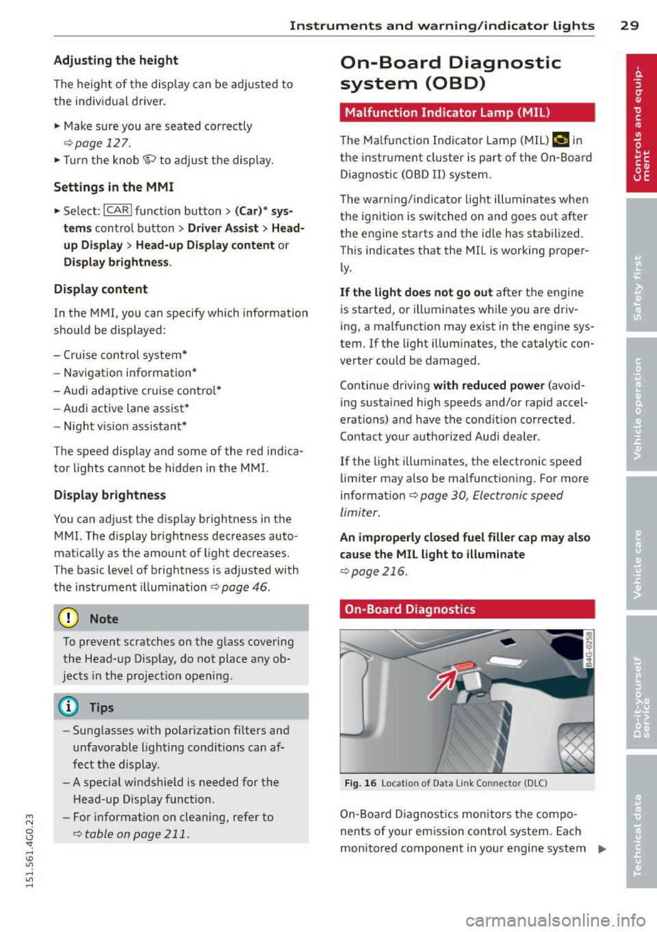
Fig. 1 6 Location o f Data Li nk Co nnector (D LC)
On-Board Diagnostics monitors the com po
nents of your emission cont ro l system. Each
monitored component in your engine system
Iii>-
Page 34 of 314
32 Opening and clo sing
Remov ing the mechanical key
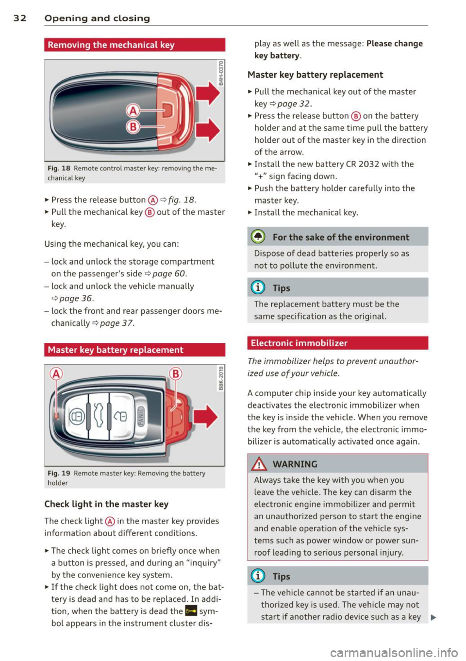
Fig. 18 Remote control master key: remo vin g the me
ch ani cal key
> Press the release button @c::> fig. 18.
.. Pull the mecha nica l key @ out of the master
key.
Using the mechan ica l key, you can:
- lock and unlock the storage compartment
on the passenger's side
c::> page 60 .
-lock and unlock the vehicle manually
<=>page 36.
-lock the front and rear passenger doors me
chanically
c::> page 37.
Master key battery replacement
Fig . 19 Remote mas ter key: Removing the batter y
ho lder
Ch eck light in the master ke y
The check light @in the master key provides
information about d ifferent cond itions .
.. The check light comes on briefly once when
a button is pressed , and during an "inquiry"
by the convenience key system .
> If the check light does not come on, the bat
tery is dead and has to be rep laced . In addi
t ion, when the battery is dead the
II sym
bol appears in the instrument cluster dis- play as well as the message:
Plea
se ch ange
key b attery.
Ma ster key battery replacement
• Pull the mechanical key out of the master
key
c::> page 32 .
.. Press the release button @ on the battery
holder and at the same time pull the battery
holder out of the master key in the direction
of the arrow .
.. Install the new battery CR 2032 with the
"+" sign facing down.
• Push the battery holder carefully into the
maste r key .
• Insta ll the mechan ica l key.
@ For the sake of the environment
D ispose of dead batteries properly so as
not to poll ute the environment.
(D Tips
The replacement battery must be the
same specification as the original.
Electronic immobilizer
The immobilizer helps to prevent unauthor
ized use of your vehicle .
A computer chip ins ide your key automatically
deactivates the electron ic immobilizer when
the key is inside the vehicle . When you remove
the key from the vehicle, the electron ic immo
bilizer is automatically ac tivated once aga in .
_& WARNING
-
A lways take the key with you when you
l eave the vehicle . T he key can disarm the
e lectronic engine immobilize r and permi t
an unauthorized person to start the engine
and enable operation of the vehicle sys
tems such as power window or power sun
roof leadi ng to serious personal injury.
(D Tips
- The vehicle cannot be started if an una u
thorized key is used . The vehicle may not
start if another radio device s uch as a key "'