AUDI S7 2013 Owners Manual
Manufacturer: AUDI, Model Year: 2013, Model line: S7, Model: AUDI S7 2013Pages: 310, PDF Size: 77.45 MB
Page 281 of 310
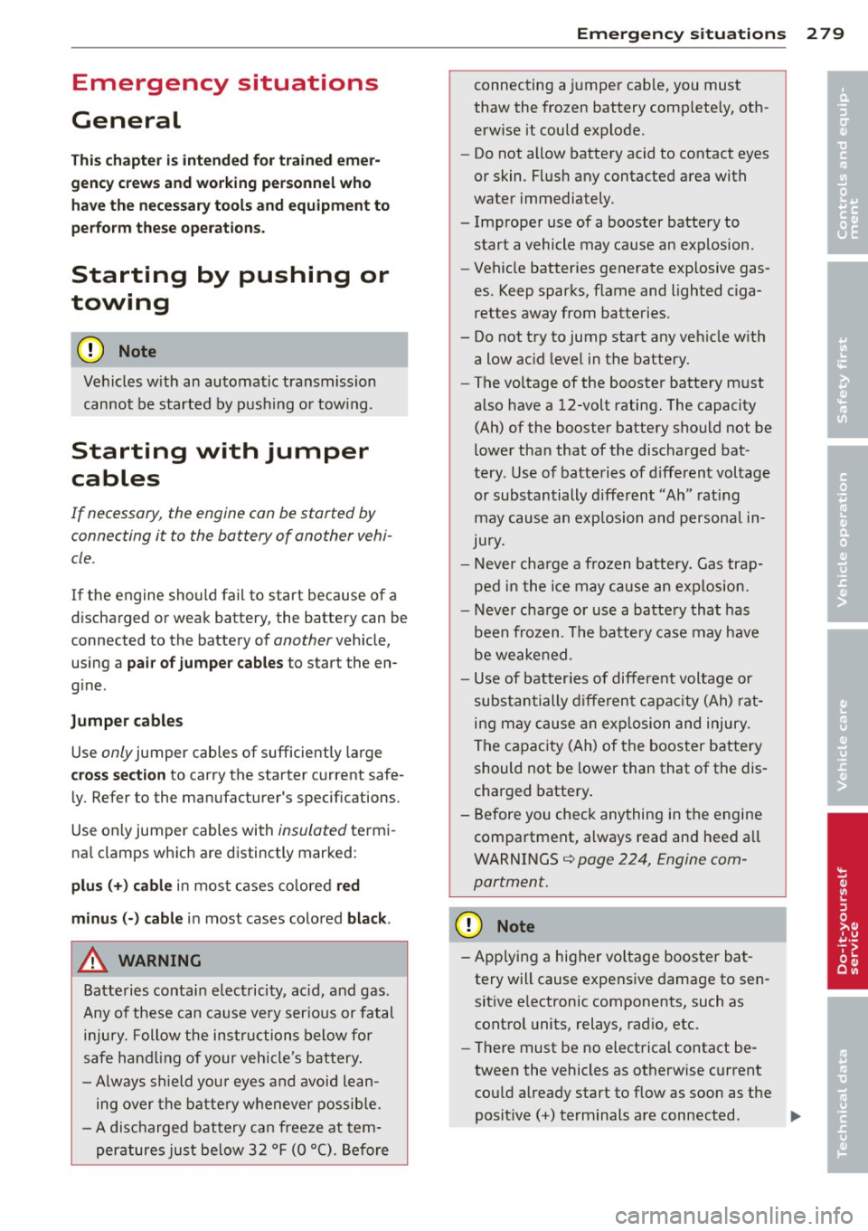
Emergency situations
General
This chapter i s intended for trained emer
gency crews and working personnel who have the necessary tools and equipment to
perform these operations.
Starting by pushing or
towing
CD Note
Ve hicles w ith an au tomatic tra nsmission
cannot be started by pus hing o r tow ing.
Starting with jumper
cables
If necessary, the engine can be started by
connecting it to the battery of another vehi
cle.
If the engine shou ld fail to start because of a
discha rged o r wea k battery, the battery can be
connected to the battery o f
another vehicle,
using a
pair of jumper cables to start the en
g ine.
Jumper cables
Use only jumper cables of sufficiently la rge
c ross section to carry the starter c urrent safe
l y. Refer to the man ufacturer's specifications.
Use only jumper cables with
insulated te rm i
na l clamps wh ic h are d istinctly marked:
plus(+) cable i n mos t cases co lore d red
minu s(-) cable
in most cases colored black .
A WARNING
Batterie s contain e lec tricity, ac id, an d gas.
A ny of these can cause ve ry ser io us or fatal
inju ry. Follow the instructions below f or
safe han dling of your veh icle's b attery .
- Alway s shield you r eyes and avoid lean
ing over the bat te ry whenever possib le.
- A dis ch arged battery c an free ze at tem
peratures ju st be low 3 2 °F ( 0 °C ). Befo re
Emergency situations 2 79
connecting a jumpe r cab le, you must
thaw the fr ozen battery c omp lete ly, ot h
erwise it could explode.
- Do not allow battery acid to contact eyes
or skin. Fl ush any contacted area with
wate r immediately.
- Improper use of a booster battery to start a vehicle may cause an explosion.
- Vehicle batter ies genera te exp losive gas
es. Keep spar ks, flame and lighted c iga
rettes away from batte ries.
- Do not try to jump start any ve hicle w ith
a low ac id leve l in the battery.
- The vo ltage of the booste r batte ry m ust
a lso have a 12-volt rating. The capacity
(Ah) of the booster battery sho uld not be
lowe r tha n that of the discharged bat
tery . U se of batte rie s of d iffe ren t voltage
or substantially diffe rent "Ah" rat ing
may c au se an exp losion and persona l in
JU ry.
- N ever cha rge a fro zen batte ry. Gas tr ap
pe d in t he ice may c ause an explosion.
- Never cha rge or use a batte ry tha t h as
been fr ozen. T he battery case may have
be weakened.
- Us e of b atter ies of differe nt voltage or
sub stant ia lly diff eren t ca pa city (Ah) ra t
i ng may c ause an ex plosion an d injury .
Th e capac ity (Ah) of the booster bat tery
should not be l ower than that of the dis
charged batte ry .
- Before you chec k any thing in the engine
compa rtment, always read an d hee d all
WARNINGS¢
page 224, Engine com
partment.
CD Note
- App lying a higher voltage booster ba t
tery will cause expens ive damage to se n
sit ive e lectronic components, such as
cont rol units, relays, rad io , etc.
- The re must be no electrical contact be
tween the vehicles as otherwise current
cou ld already start to f low as soon as the
posit ive(+) te rm inals a re c onnected. ..,. •
•
Page 282 of 310
280 Emergency situations
@ Tips
The discharged battery must be properly
connected to the vehicle's electrical sys
tem. When jump starting or charging the
battery, never connect the negative
ground cable to the battery negative post
because the batte ry manager system must
be able to detect the battery 's state of
charge. Always connect the negative
ground cab le to the negative ground post
of the battery manager control unit.
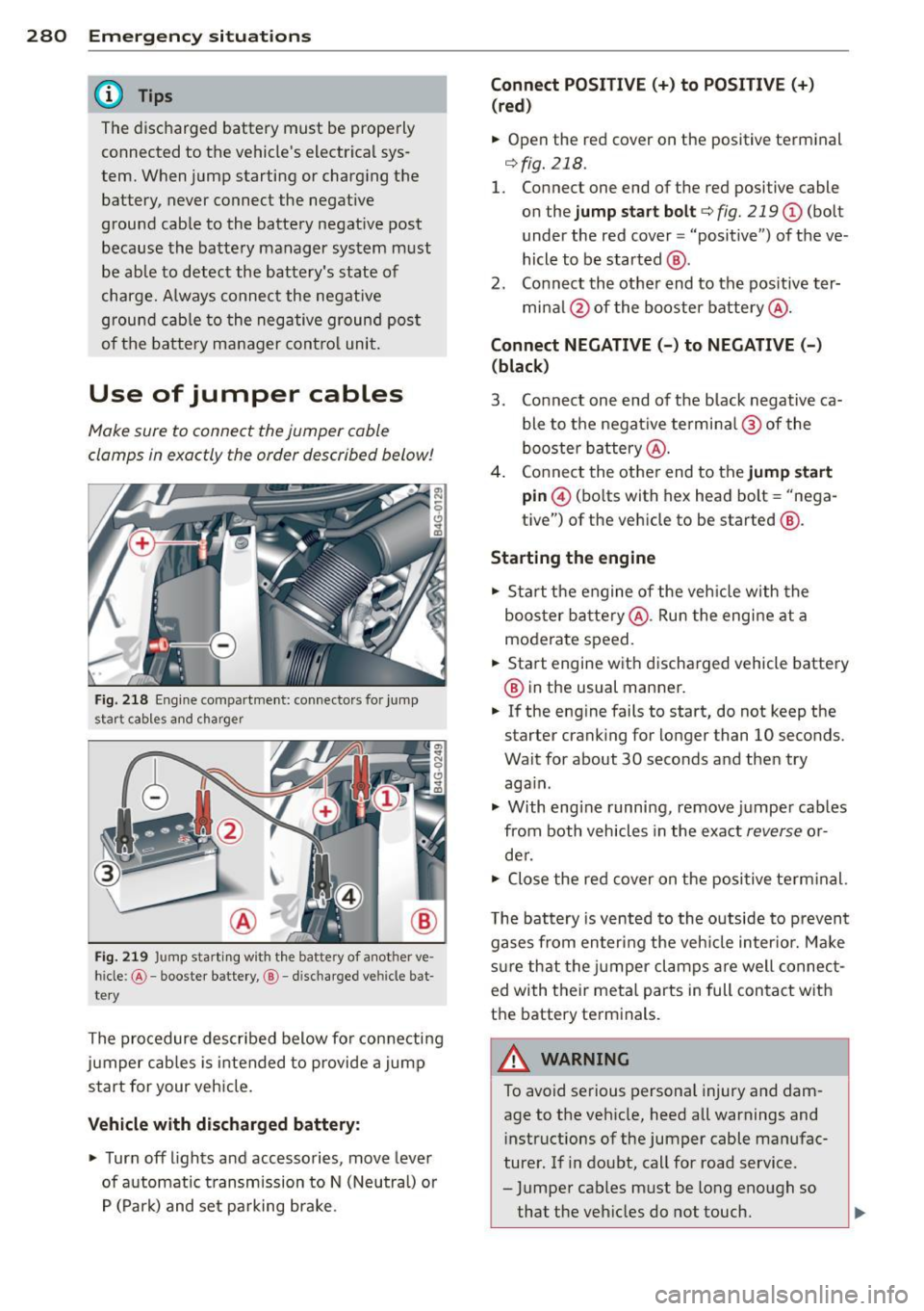
Use of jumper cables
Make sure to connect the jumper cable
clamps in exactly the order described below!
Fig. 218 Engine compartment: connecto rs for jump
start cables and charger
Fig. 219 Jump start ing with the battery of another ve·
hide: @-booster battery, @-discharged ve hicle bat
tery
The procedure described below fo r connecting
jumper cables is intended to provide a jump
start for your vehicle.
Vehicle with discharged battery:
.,. Turn off lights and accessories, move lever
of automatic transmission to N (Neutral) or
P (Park) and set parking brake.
Connect POSITIVE(+) to POSITIVE(+)
(red)
.,. Open the red cover on the positive terminal
¢fig. 218.
1. Connect one end of the red positive cable
on the
jump start bolt c::;, fig. 219 @ (bolt
under the red cover = "positive") of the ve
hicle to be started @.
2. Connect the other end to the positive ter-
mina l@ of the booster battery@.
Connect NEGATIVE (-) to NEGATIVE (-)
(black)
3. Connect one end of the black negative ca
ble to the negat ive terminal @ of the
booster battery @.
4. Connect the other end to the
jump start
pin © (bolts with hex head bolt= "nega
tive") of the vehicle to be started @.
Starting the engine
.,. Start the engine of the veh icle with the
booster battery@. Run the engine at a
moderate speed .
.,. Start engine with d ischarged vehicle battery
@ in the usual manner.
.,. If the engine fails to start, do not keep the
starter cranking for longer than 10 seconds.
Wait for about 30 seconds and then try aga in .
.,. With eng ine running,
remove jumper cables
from both vehicles in the exact
reverse o r
de r .
.,. Close the red cover on the positive term inal.
T he battery is vented to the outside to prevent
gases from entering the veh icle inter ior. Make
sure that the jumper clamps are well connect
ed with their metal parts in full contact with
the battery terminals.
_& WARNING
To avoid serious personal injury and dam
age to the vehicle, heed all warnings and
instructions of the jumper cable manufac
turer. If in doubt, call for road service .
- Jumper cables must be long enough so
that the veh icles do not touch.
-
Page 283 of 310
-When connecting jumper cables, make
sure that they cannot get caught in any
moving parts in the eng ine compart
ment .
- Before you check anything in the engine
compartment, always read and heed all
WARNINGS ¢
page 224, Engine com
partment.
(D Note
Improper hook-up of jumper cables can r u
in the generator.
- Always connect POSITIVE(+) to POSI
TIVE(+), and NEGA TIVE( -) to NEGATIVE
( - ) ground post of the battery manager
control u nit .
- Check that all sc rew plugs on the battery
cells are screwed in firmly. If not, tighten
pl ugs p rior to connecting clamp on nega
tive batt ery terminal.
- P lease note that the procedure for con
nect ing a jump er cable as describe d
above applies spec ifically to the case of
your vehi cle be ing j ump s tarted. When
you are giving a jump star t to anothe r ve
hicle, do
not connec t the negative( -) ca
b le to the negat ive (-) term inal on the
discharged battery@¢
fig. 219. In
stead, securely connect the negative(-)
cable to e ither a solid metal component
that is firmly bolted to the engine block
or to the engine block itself.
If the bat
te ry tha t is being charged does not vent
to the ou tside, es ca ping b attery gas
could ignite and ex plode!
Emergency towing
with commercial tow
truck
General hints
Your Audi requires special handling for tow
ing .
The fo llow ing informa tion is to be used by
commercia l tow tr uck operators who know
how to ope rate thei r equipmen t sa fe ly.
Emergenc y situ ation s 281
-Ne ver tow your Audi. Towing will cau se
damage to the engine and tran smission.
- Never wrap the safety chain s or w inch ca
ble s around the brake lines.
- To prevent unnece ssary damage , your Audi
must be transported with a flat bed tru ck.
- To load the vehicle on to the fl at bed , use
the towing loop found in the vehicle tools
a nd attach to the front or rear anchora ge
¢page 281 and ¢page 282 .
_& WARNING
A vehicle being towed is not safe for pas
sengers. Never allow anyo ne to ride in a
vehicle be ing towed, for any reason.
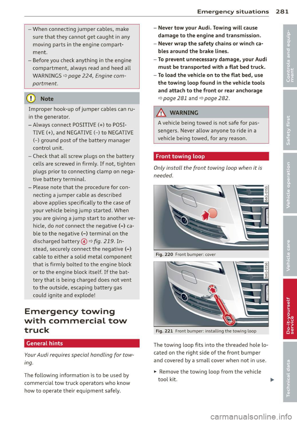
Front towing loop
Only install the front towing loop when it is
needed.
Fig. 22 0 Front bumpe r: cove r
Fig. 22 1 Front bu mpe r: in stall ing t he tow ing loop
-
The towing loop fits into the threaded hole lo
cated on the right s ide of the front bumpe r
and cove red by a sma ll cover when not in use.
.. Remove the tow ing loop from the vehicle
too l kit .
Page 284 of 310
282 Emergency situations
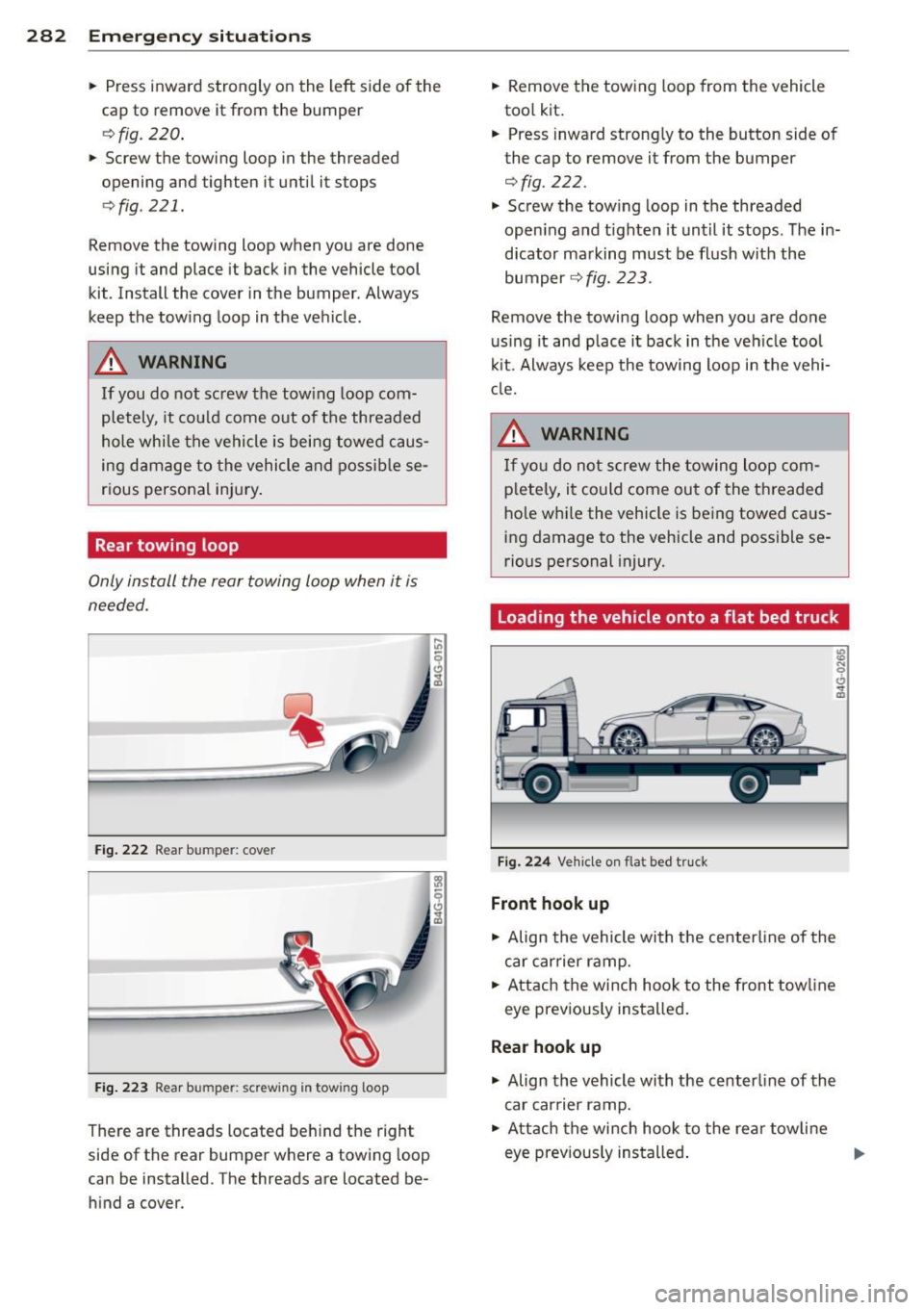
• Press inward strongly on the left side of the
cap to remove it from the bumper
¢ fig . 220 .
• Screw the towing loop in the threaded
opening and tighten it until it s tops
¢ fig . 221.
Remove the towing loop when you are done
using it and place it back in the vehicle tool
kit . Install the cover in the bumper. Always
keep the towing loop in the vehicle.
A WARNING
If you do not screw the tow ing loop com
pletely, it could come out of the threaded
hole while the vehicle is being towed caus
ing damage to the vehicle and possible se
rious personal injury.
Rear towing loop
Only install the rear towing loop when it is
needed.
Fig . 222 Rear bum per: cover
Fig. 223 R ear bum per: scr ew in g in tow ing loop
There are threads located behind the right
side of the rear bumper where a towing loop
can be installed . The threads are located be
hind a cover.
-
• Remove the towing loop from the vehicle
tool kit.
• Press inward strong ly to the button side of
the cap to remove it from the bumper
¢fig. 222.
.,. Screw the tow ing loop in the threaded
open ing and t ighten it until it stops. The in
dicator marking must be flush with the
bumper
c::> fig. 223 .
Remove the towing loop when you are done
using it and place it back in the veh icle tool
kit. Always keep the towing loop in the vehi
cl e.
A WARNING
If you do not screw the towing loop com
pletely, it could come out of the threaded
hole while the vehicle is being towed caus
ing damage to the vehicle and possible se
rious personal injury.
Loading the vehicle onto a flat bed truck
Fig. 224 Vehicle on flat bed tr uck
Front hook up
.,. Align the vehicle with the centerline of the
car carrier ramp .
.,. Attach the winch hook to the front tow line
eye previously installed.
Rear hook up
.,. Align the vehicle with the centerline of the
car earner ramp.
• Attach the winch hook to the rear towline
eye previous ly installed .
-
Page 285 of 310
@ Tips
Check carefully to make sure the hook-up
is secure before moving the car up the flat
bed truck ramp .
Vehicle transport
Whenever you hov e your vehicle transported,
be sure to note the following :
(D Note
Mount the tie-down chains/cables over the
running surface (circumference) of the
tires. Never secure the vehicle by the axle,
the suspension struts or the front or rear
towline eye . For technical reasons, the
pressure in the suspension struts may
change du ring the transport and this will
adve rsely affect vehicle handling.
Lifting vehicle
Lifting with workshop hoist and with
floor jack
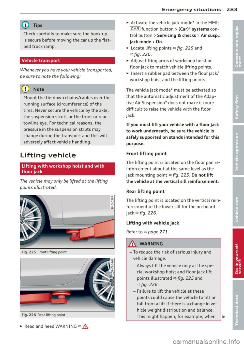
The vehicle may onl y be li~ed at the lif ting
points illu stra ted.
Fi g. 2 25 Front l ift ing po int
Fig. 226 Rea r lifti ng poin t
.. Read and heed WARNING c::> ,& .
:;:; N 0 6 ., a,
Emergenc y situ ation s 283
.. Activate the vehicle jack mode * in the MMI:
!CAR I function button > (C ar)* s ystem s con
trol button>
Se rvic ing & check s> Air su sp. :
jack m ode > On .
.. Loca te lifting poin ts c::> fig. 225 and
c::> fig . 226 .
.. Adjust lifting arms of workshop hoist o r
floor jack to match veh icle lifting points.
.. Insert a rubbe r pad between the floor jack/
workshop hoist and the lift ing po in ts.
The vehicle jack mode* must be activated so
that the automat ic adjustment of the Adap
tive Air Suspens ion* does not make it more
di fficu lt to raise the vehicle with the floor
jack.
If yo u must lift your v ehi cle with a floor jack
t o wo rk und ern eath , be sure th e vehicle i s
s af ely s upported on stand s intended for thi s
purpo se.
Front lifting point
The lifting po int is located on the floor pan re
inforcement abo ut at the same level as the
ja ck mounting point
c::> fig. 225 . Do n ot lift
t h e ve hicle at th e verti cal sill reinforc em ent .
Re ar lifting point
The lifting point is located on the vertical rein
fo rcement of the lower sill for the on-boa rd
ja ck
c::> fig. 226 .
Lifting with vehicle j ack
Re fer to c::> page 2 71 .
A WARNING
-To reduce the risk of ser ious injury and
veh icle damage .
- Always lift the veh icle only at the spe
cia l workshop hoist and floor jack lift
po ints illust rated
c::> fig . 225 and
c::> fig . 226.
- Failu re to lift the vehicle at these
po ints could cause the vehicle to tilt or
fall from a lift if there is a change in ve
hicle weight distribution and balance .
This might happen, for example, when
-
Page 286 of 310
284 Emergency situations
heavy components such as the engine
b lock or transmiss io n are removed.
- W he n removing heavy components like
these, ancho r vehicle to ho ist o r add cor
responding weig hts to ma inta in the cen
ter of g ravity . Othe rwise, the vehicle
might tilt or s lip off t he hoist, causing
ser ious p erson al injury.
(D Note
-Be awa re of the follow ing points befo re
li fting the vehicle:
- The vehicle should never be lifted or
jacked up from underneath the engine oil pan, the transmission housing, the
front or rear axle or the body side
membe rs. This could lead to ser ious
damage.
- To avoid damage to the underbody or
chassis frame , a rubber pad must be
i nserted between the floor jack and
the l ift points.
- Before driving over a workshop hoist,
check that the veh icle weight does not
exceed the permissible lifting capacity
of the hoist .
- Before driving over a workshop hoist,
ensure that there is sufficient clear
ance between the hoist and low parts
of the vehicle.
Page 287 of 310
General information Explanation of
technical data
Som e of t he technical data listed in this man
ual requires further explanation .
The technical data for your vehicle is listed in
the charts starting on
Q page 287 . This sec
tion provides general information, notes and r estr ictions wh ich app ly to this data.
Vehicle identification
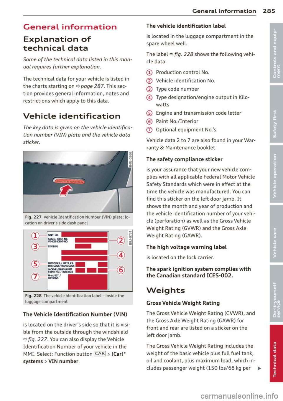
The key data is given on the vehicle identifi ca
tion number ( VIN) plate and the vehicle data
sti cker .
Fig. 22 7 Vehicle Ident ific atio n Num ber (V lN) p la te: lo
cation o n dri ve r"s s ide das h pa nel
Fi g. 2 28 The ve hicle iden tifi cat ion label -inside the
l u ggage co mpartme nt
The Vehicle Identification Number (VlN)
is located on the d river's side so tha t it is v is i
b le from the outside throug h the windshield
Q fig . 22 7. You can also d isplay the Vehicle
Identification N umber of your vehicle in the
MMI. Select: Function button
!CAR I> (Car )*
systems
> VIN number .
General inform ation 285
The vehicle identification label
is lo cated in the l uggage comp artment in the
spare whee l we ll.
T he label
r:::> fig. 228 shows th e fo llow ing vehi
cl e data :
(D Product ion cont ro l No.
@ Vehicle identific ation No.
@ Type code number
© Type designat ion/e ngine o utput in K ilo-
wat ts
® Engine and transm ission code letter
® Pa int No ./lnterior
0 Op tio nal eq uipment No.'s
Vehicle data 2 to 7 are a lso found in your War
ranty
& Mai nte nance bookle t.
The safety compliance sticker
is your assurance that your new vehicle com
plies with a ll applicab le Fede ral Motor Vehicle
Safety Standards which were in effect at the
time the ve hicle was manufactur ed . You can
find this sticke r o n the left doo r jamb.
It
sh ows the month an d ye ar of pro duction and
t he ve hicl e ident ificat io n number of yo ur vehi
cle (perforation) as well as the G ross Vehicle
Weight Rating (GVW R) and the Gross Axle
Weight Rating (GAWR) .
The high voltage warning label
is lo cate d on the lock ca rrie r.
The spark ignition system complies with
the Canadian standard ICES-002.
Weights
Gross Vehicle Weight Rating
T he Gro ss Vehicle Weigh t Rat ing (GVWR), and
t he Gross Axle We igh t Rati ng (GAWR) for
fron t and rear are listed on a sticker on the
l eft door jamb .
T he Gro ss Vehicle Weigh t Rat ing incl udes the
weight of the bas ic vehicle plus f ull fuel t ank,
oi l and coo lant, plus maximum load, which in
cludes passen ger we ight (150 lbs/68 kg per ..,.
Page 288 of 310
28 6 G enera l inform ation
designated seating position) and luggage
w eight ¢.&, .
Gross Axle W eight Rating
The Gross Axle Weight Rating is the maximum
l oad that can be applied at each axle of the
vehicle ¢Lr!, .
Vehicle capacit y weight
The vehicle capac ity we ight (max . load) is list
ed either on the dr iver's side B-pilla r or inside
the fuel filler flap.
Roof weight
T he m aximum perm iss ible roo f we igh t is
22 0 lb (100 kg ). The roof weight is made up
of the weight of the roof rack system and the
weight of the object be ing transported
¢ page 62 , Loading the roof rack.
A WARNING
- T he ac tual Gross Axle Weight Rat ing at
the front and rear axles shou ld not ex
ceed the permissible weights, and their
combination must not exceed the Gross
Vehicle Weight Rat ing .
- Exceeding permissib le weight ratings can
result in vehicle damage, accidents and
personal injury.
{[) Note
- The vehicle capacity weight figures apply
when the load is distributed evenly in the
vehicle (passengers and luggage) . When
transporting a heavy load in the luggage
compartment, carry the load as near to
the rear axle as possib le so that the vehi
cle 's ha ndling is not impa ired.
- Do not exceed the maximum permissible
axle loads or the max imum gross vehicle
weight . Always remember that the vehi
cle's handling will be affected by the ex
tra load . Therefore, adjust your speed ac
cord ingly.
- Always obse rve lo ca l regu lations.
-
Dimensions
The specifications refer to the basic model.
Diff erences may occur dep ending on th e mod
el type and options o rdered, for example, ti re
si zes.
~ Note
When driving up steep ramps, on rough
roads, over curbs, etc . it is important to re
member that some parts of your vehicle,
such as spo ilers or exhaus t system compo
nents, may be close to the ground . Be
careful not to damage them .
Page 289 of 310
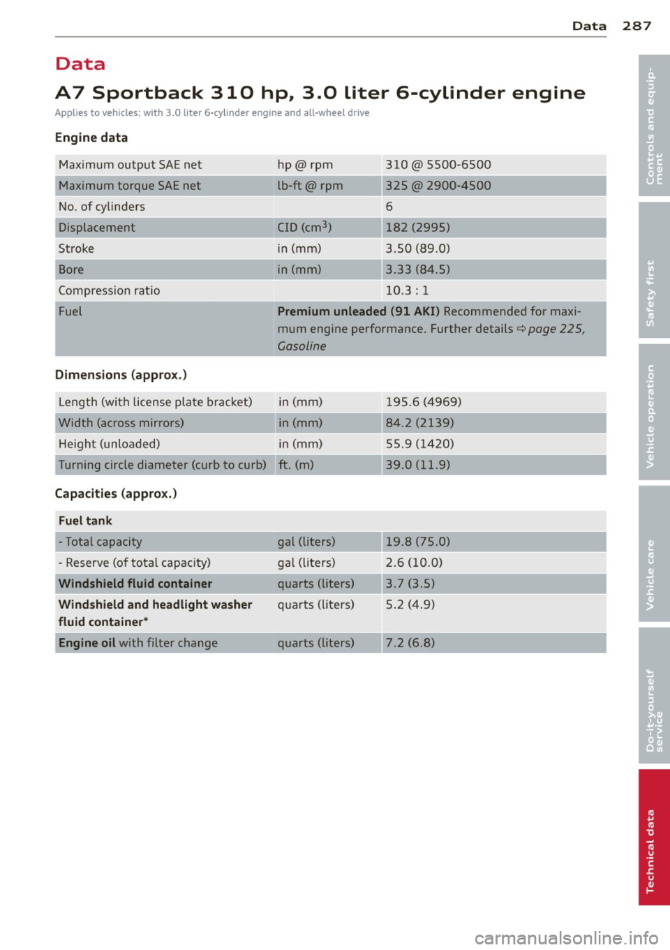
Data
Data
A7 Sportback 310 hp., 3.Q, liter 6-cylinder engine
Applies to vehicles: with 3.0 liter 6-cyli nde r engine and all-wheel d rive
Engine data
Maximum output SAE net
Maximum torque SAE net
No . of cylinders
Displacement
Stroke
Bore
Compression ratio
Fuel
Dimensions (approx .)
L eng th (wit h license pl ate brac ket)
Width (across mirrors) He igh t (unloaded) hp@
rpm
lb-ft@ rpm
C ID (cm
3
)
in (mm)
in (mm)
-- ,
__ ...
310@ 5500-6500
325 @ 2900-4500
6
182 (2995)
3.50 (89 .0)
3 .33 (8 4.5)
10 .3 : 1
Premium unleaded (91 AKI) Recommended for maxi
mum engine performance. Further details
Qpage 225,
Gasoline
in (mm) 1 95.6 ( 4969)
in (mm) 84.2 (2139)
in (mm) 55.9 (1 420)
Turning circle diameter (curb to curb) ft. (m) 39. 0 (11.9)
Capacities (appro x.)
Fuel tank
- Total capacity
- Reserve (o f to tal capacity)
Windshield fluid container
Windshield and headlight washer
fluid container *
Engine oil
with filter change gal (liters)
19.8 (75.0)
g
al (li ters) 2. 6 (10.0)
quarts (liters) 3.7 (3.5)
qu arts ( liters) 5 .2 ( 4.9)
quarts (lite rs) 7.2 (6.8)
287
•
•
Page 290 of 310
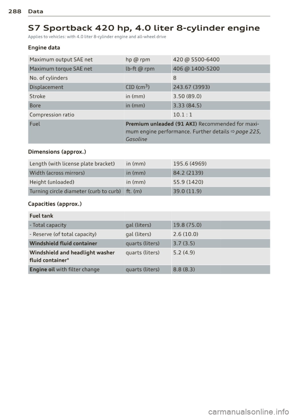
288 Data
S7 Sportback 420 hp, 4.0 liter a-cylinder engine
Applies to vehicles: with 4.0 liter 8-cylinder engine and all-wheel drive
Engine data
Maximum output SAE ne t
Maximum torque SAE net
No. of cylinders
Stroke
Bore
Compressio n ratio
Fuel
Dimensions ( approx .)
Leng th (with lice nse pl ate bra cket)
Width (across mirrors) He igh t (unloaded) hp@ rpm
lb-ft@ rpm
CID (cm
3 )
in (mm)
in (mm)
__ ,
-~ .. ,
420 @ 5500-6400
406@ 140 0-5200
8
24 3 .67 (3993)
3 .50 (89 .0)
3 .33 (84.5)
10 .1: 1
Premium unleaded (91 AKI) Recommended for maxi
mum engine performance . Further details¢
page 225,
Gasoline
in (mm) 1 95.6 (4969)
in (mm) 84.2 (2139)
in (mm) 55.9 (1 420)
Turning circle diamet er (curb to curb) ft . (m) 39 .0 (11.9)
Capacities (appro x.)
Fuel tank
- Total capacity
- Reserve (o f to tal capacity)
Windshield fluid container
Windshield and headlight wa sher
fluid container *
Engine oil
with filter c hange gal (li
ters)
19 .8 (75 .0)
gal (li ters) 2. 6 (10. 0)
q uarts (lit ers) 3 .7 (3 .5)
qu arts ( li1ters) 5 .2 ( 4.9)
quarts (li te rs) 8 .8 (8.3)