display AUDI S8 2008 Workshop Manual
[x] Cancel search | Manufacturer: AUDI, Model Year: 2008, Model line: S8, Model: AUDI S8 2008Pages: 404, PDF Size: 52.7 MB
Page 146 of 404
___ A_ d
_ a__,p_ t_ i_ v _e_ C_ r_ u_ is_e_ C_ o_n _ t_ r_o _l ___________________________________________ _
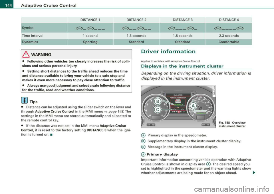
DISTANCE 1 DISTANCE 2 DISTANCE 3 DISTANCE 4
Symbol
~-~---~--~--~---~-~----~
-
Time interval
Dynamics 1 second
Sporting 1.3 seconds
Standard 1
.8 seconds
Standard 2.3
seconds
Comfortable
& WARNING
• Following other vehicles too closely increases the risk of colli
sions and serious personal injury.
• Setting short distances to the traffic ahead reduces the time
and distance available to bring your vehicle to a safe stop and
makes it even more necessary to pay close attention to traffic.
• Always use good judgment and select a safe following distance
for the traffic, road and weather conditions.
[ i) Tips
• Distance can be adjusted using the slider switch on the lever and
th rough
Adaptive Cruise Control in the MMI menu => page 148. The
settings in the MMI menu are stored automatically and allocated to
the remote control key.
• If the distance was not set in the MMI menu
Adaptive Cruise
Control ,
it is rese t to the fa ctory setting DISTANCE 3 when the igni
tion is turned on. •
Driver information
Applies to ve hicles: w it h Ad aptive Cru ise Co ntro l
Displays in the instrument cluster
Depending on the driving situation , driver information is
displayed in the instrument cluster.
© Primary display in the speedometer .
Fig. 158 Overview
instrument cluster
@ Supplementary display in the instrument cluster display.
© Message in the instrument cluster display.
© Primary display
Important information concerning vehicle operation with Adaptive
Cruise Control is shown in display area @. Th e desired sp eed you
set is highlighted in the speedometer and the warning lights show
wh ether adjus tmen ts are being mad e for an objec t ahead .
.,,
Page 147 of 404
_____________________________________________ A_ d..:.a..! p..:. t
_ i_ v _ e.;__ C.,...._ ru.;__ is..:. e.;__ C.::..: o..:.n..:.. t:.:. r..: o ..:. I_--..J_
This information is always displayed. Display area © is therefore
called the
primary di sp la y .
© S upple men tary displ ay
In display area @ information from the navigation system and the
trip computer is disp layed in addition to information about Adaptive
Cruise Control.
You can select among the different information by repeated brief taps on the RESET button on the windshield wiper
lever => page 39,
"Operation ".
Particularly on your first trips with Adaptive Cruise Control, the
s uppl em en ta ry di spla y should be turned on.
@ Message
The information in area © is not displayed permanently. Informa
tion is displayed on ly if you change the time interval , if there is a
malfunction or if the Adaptive Cruise Control is turned off. •
Applies to vehicles : with Ada ptive C ruise Cont rol
Primary display in the speedometer
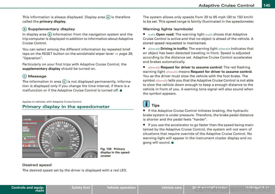
De sire d sp eed
Fig . 159 Prim ary
di spl ay
in the s pee d
o m ete r
The desired speed set by the driver is displayed with a red LED.
Contro ls a nd eq uip
ment
The system al lows only speeds from 20 to 95 mph (30 to 150 km/h)
to be set. This speed range is faintly illuminated in the speedometer.
W arn ing lights (symbols )
• ""c:::, Open road: The warning light ,,.,c:::, shows that Adaptive
Cruise Control is active and that no object is ahead of the vehicle . A
stored speed requested is maintained .
• c::::,11 .. c:::, Driving i n tr aff ic: The warning light c:::,11«c:::, indicates that
an object has been detected travel ing in front . Speed is adjus ted
according to the distance set. Adaptive Cruise Control accelerates
and brakes automatica lly.
• c:::,,, ,,c:::, Re quest f or driver t o assume control : The red flashing
warning light
c::::,11 .. c:::, means Reque st for driver to assume control .
You as the driver must slow the vehicle with the foot brake . The
symbo l
c::::,11,,c:::, tells you that the Adaptive Cruise Control is not able
to s low the vehic le down enough to keep a enough distance to the
vehicle in front o f you . A warning tone signal wi ll also sound when
the symbol appears.
[ i ] Tip s
• If the Adaptive Cruise Control initiates braking, the hydraulic
brake system is under pressure. Therefore, the brake pedal distance
is shorter and the peda l feels "harder" .
• I f you use the accelerator to go faster than the speed being main
tained by the Adaptive Cruise Control, the system will not warn of
situations that require override of the Adaptive Cruise Control. No
warning light will appear in the instrument cluster display and no gong wil l sound .•
Vehicle care I I irechnical data
Page 148 of 404
__ _!_A~d~a~p~t~i~v~e~C:::.r~u~is~ e~C~o'.!.n~t:!r~o~I ___________________________________________ _
Ap plies to ve hicles : wi th Ad aptive Crui se Co ntro l
Supplementary display
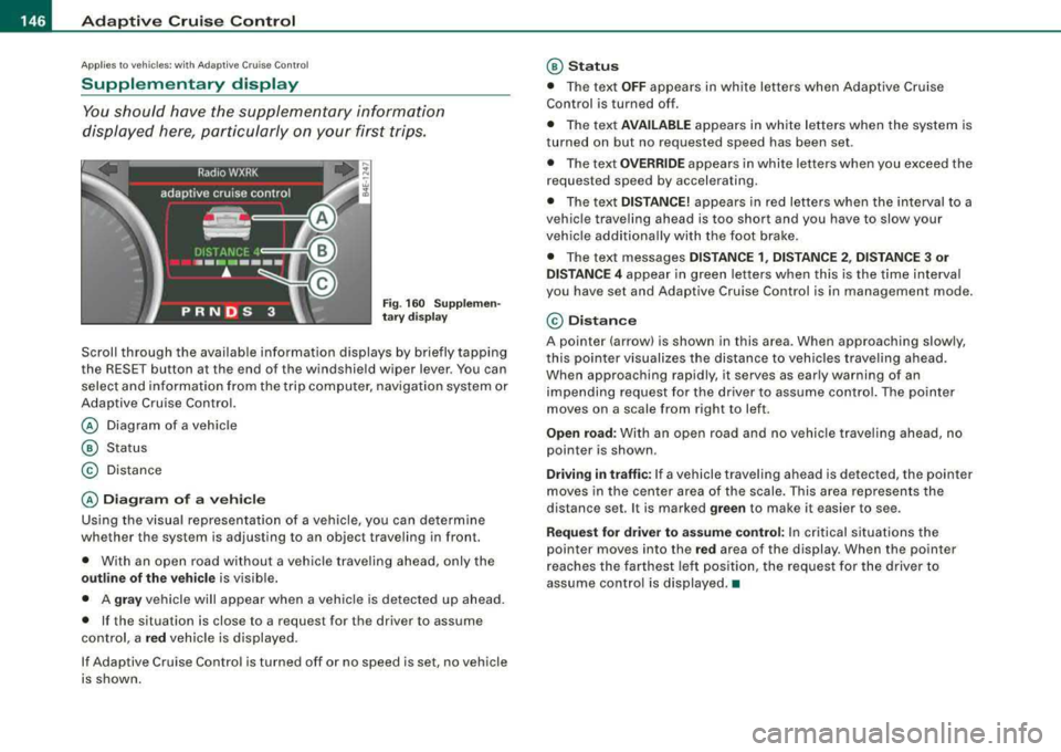
You should have the supplementary information
displayed here, particularly on your first trips.
F ig . 16 0 S upplem en
t a ry di sp lay
Scrol l through the avai lab le information displays by briefly tapping
the RESET button at the end of the windshie ld wiper lever . You can
select and information from the trip computer, navigation system or
Adaptive Cruise Con trol.
@ Diagram of a vehic le
@ Status
© Distance
@ Diagram of a ve hi cle
Using the v isual representation of a vehicle, you can determine
whether the system is adjusting to an object traveling in fron t.
• With an open road without a vehicle trave ling ahead, only the
outline of the vehi cle is visible .
• A
gray vehicle will appear when a vehic le is de tec ted up ahead.
• If the situation is close to a reques t for the driver to assume
control, a
red vehicle is displayed.
If Adaptive Cruise Control is turned off or no speed is set, no vehicle
is shown.
@ Statu s
• The te xt OFF appears in white letters when Adaptive Cruise
Control is turned off.
• Th e text
AVAILABLE ap pears in white letters when the system is
turned on but no requested speed has been set .
• The text
O V ERRIDE appears in white letters when you exceed the
reques ted speed by accelerating .
• The text
DISTANCE! appears in red letters w hen the interval to a
vehic le traveling ahead is too short and you have to slow your
vehic le add itionally wi th the foot brake.
• The text messages
DISTANCE 1 , DISTANCE 2 , DI STANCE 3 or
DISTANCE 4
appear in green let ters when th is is the time interval
you have set and Adaptive Cruise Cont rol is in management mode.
© Di stan ce
A pointe r (arrow) is shown in this area. When approaching slowly,
this poin ter visual izes the distance to veh icles traveling ahead.
When approaching rapid ly, it serves as early warning of an
impending request for the dr iver to assume contro l. The po inter
moves on a scale from right to left .
Open road: With an open road and no vehicle trave ling ahead, no
pointer is shown .
Driving in traff ic: If a vehicle trave ling ahead is detected, the pointer
moves in the center area of the scale. This area represen ts the
distance set. It is marked
green to make it easier to see .
Request for driver to assume control: In critical situations t he
pointer moves into the
red area of the display. When the pointer
r eaches the farthe st left position, the request for the d river to
assume control is displayed. •
Page 149 of 404
_____________________________________________ A_ d_a ....: p_ t_ i_ v _e_ C_ ru_ is_ e_ C_ o_n_ t_ r_o _ l _ __._
Ap plie s to vehic les: with Adaptive Cru ise Co nt rol
Messages
The text messages and symbols shown in this area of the
display are not displayed perm anently .
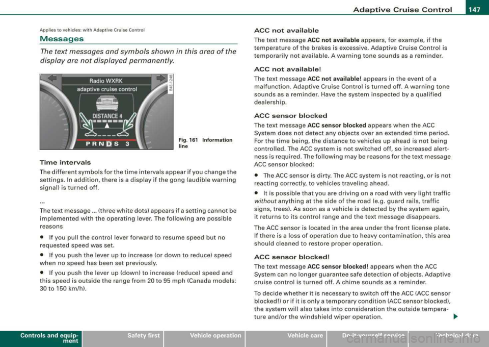
Time interval s
Fig . 16 1 Informa tion
lin e
The different symbols for the time intervals appear if you change the
settings. In addition, there is a display if the gong (audible warning
signa l) is turned off.
The text message ... (three white dots) appears if a setting cannot be
implemented with the operat ing lever. The fol lowing are possible
reasons
• If you pu ll the control lever forward to resume speed but no
requested speed was set.
• I f you push the lever up to increase (or down to reduce) speed
when no speed has been set previously.
• I f you push the lever up (down) to increase (reduce) speed and
this speed is outside the range from 20 to 95 mph !Canada models:
30 to 150 km/h) .
Controls a nd eq uip
ment
A CC not a vailab le
The text message ACC not av ailabl e appears, for example, if the
temperature of the brakes is excessive . Adaptive Cruise Control is
t emporarily not availab le . A warning tone sounds as a rem inder.
A CC not available !
The text message ACC not av ailabl e! appears in the event of a
malfunction. Adaptive Cruise Control is turned off . A warning tone
sounds as a reminder. Have the system inspected by a qua lified
dea lersh ip.
ACC senso r blocked
The text message AC C s en so r blo cked appears when the ACC
System does not detect any objects over an extended time period .
For the time being, the distance to vehicles up ahead is not being
cont rolled . The ACC system is not switched off, so increased alert
ness is required. The following may be reasons for the text message
ACC sensor blocked:
• The ACC sensor is dirty. The ACC system is not react ing, or is not
reacting correctly, to vehic les traveling ahead.
• It is possible that you are driving on a road with very light traffic
without any thing at the side of the road (e.g. guard rai ls, traffic
s igns, trees). As soon as a vehicle is detected by the system again,
it returns to its control range and the text message d isappears .
The ACC sensor is located in the area under the front license plate .
I f there is a loss of operation due to heavy contamination, this area
should cleaned to restore proper operation.
AC C senso r bl ock ed!
The text message ACC sensor blocked! appears when the ACC
System can no longer guarantee safe detection of objects . Adaptive
cruise control is turned off . A chime sounds as a reminder.
To decide whether it is necessary to switch off t he ACC (ACC sensor
blocked!) or if it is only a temporary condition (ACC sensor blocked),
the system wi ll a lso takes into cons ideration the outside tempera -
ture and/or the windshield wiper operation .
.,_
Vehicle care I I irechnical data
Page 150 of 404
___ A_ d_a_ p_ ti_v _ e_ C_ ru_ is_ e_ C_ o_n_ t_ r_ o _ l ___________________________________________ _
The ACC sensor is dirty or blocked (e.g. leaves, snow).
The ACC sensor is located in the area under the front license plate.
If there is a loss of operation due to heavy contamination, this area
should cleaned to restore proper operation.
EPB activation
The text message EPB activation appears if emergency braking was
initiated with the Electromechanical Parking Brake (EPBl. Adaptive
Cruise Control is turned off. A gong sounds as a reminder.
ESP activation
The text message ESP activation appears if the Electronic Stabiliza
tion Program (ESP) has intervened to take control in a critical driving
situation. In this case Adaptive Cruise Control is automatically
turned off . A gong sounds as a reminder .
Speed range
The text message Speed range appears if the current speed is too
low to set or to hold the requested speed.
When setting a desired speed, it must be at least 20 mph (30 km/h).
At speeds below 17 mph (25 km/h), the cruise control is turned off.
Shift lever position!
The text message Shift lever position! appears when the shift select
lever is moved to position
N. In this position, Adaptive Cruise
Control is not available. •
Applies to veh ic les: with Ad apt ive Crui se Contro l
Settings in MMI
The time interval can be set in MM/.
-Press the [CAR] function button.
-Select Systems in the CAR menu.
Fig. 162 MMI display :
Adaptive Cruise Control
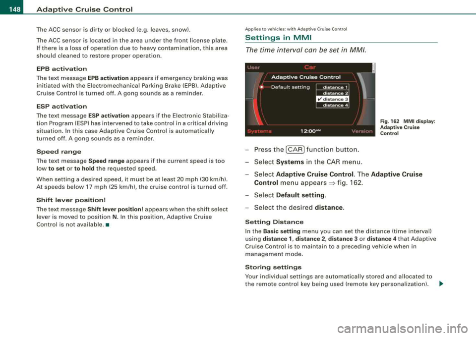
-Select Adaptive Cruise Control. The Adaptive Cruise
Control
menu appears~ f ig . 162.
-Select Default setting .
-Select the desired distance.
Setting Distance
In the Basic setting menu you can set the distance (time interval)
using
distance 1, distance 2, distance 3 or distance 4 that Adaptive
Cruise Control is to maintain to a preceding vehicle when in
management mode.
Storing settings
Your individual settings are automatically stored and allocated to
the remote control key being used (remote key personalization) .
~
Page 154 of 404
-
Audi lane assist
----------------
I Not re ad y: The yellow ind icator light shows that the system is
t urned on but unab le to send a warning . This can be due to the
following:
• There are no boundary lines, or there is on ly one boundary line
present .
• The boundary lines are not detected (e.g. due to snow, dirt, wet
conditions or light shining into the camera lens) .
• More than two boundary lines (such as at construction sites) are
located in the vehicle's lane .
• The vehicle's speed is below the speed needed to activate it,
which is abou t 40 mph (65 km/h).
• The lane is narrower than about 8 ft . (2 .5 m), or wider than about
16
ft . (5 m).
• The curve is too sharp .
Notes on th e instr umen t clu ste r displa y
When the lane assist turns off automatically , the instrument cluster
indicator goes out and one of the following messages appears on
the display:
Audi lan e assist not available: C urre ntl y no se nsor vis ion
This message appears when the camera can no longer function
because it cannot detect the boundary lines. This may be due to the
following :
• The exterior s ide of the camera viewing
window => page 151,
fig. 169 is covered with dirt or ice. Clean this part of th e windshield.
• The camera v iew ing window is fogged up on the inside. In t his
case, wait until the fog disappears before turning lane assist on
aga in.
• The system was unable to detect boundary lines over an
extended period of time due to road conditions (such as snow
covered lanes). Do not turn lane assist on again unti l the lines can
be more easily detected .
Audi lane assist not ava ila bl e
A temporary malfunction is preventing lane assist from operating .
Try turning on lane assist again a t a la ter t ime.
Audi l ane ass is t: sys te m f ault
T he system should be checked by an authorized Audi dealer or other
qual ified workshop .
[ i ] Tips
• Make sure that the camera viewing window => page 151, fig. 169
is not covered by stickers or similar objects .
• Always keep the camera view ing w indow c lean . This can usual ly
b e don e by op erat ing the windshield wipers. •
App lies to vehicles: w it h l ane assist
MMI settings
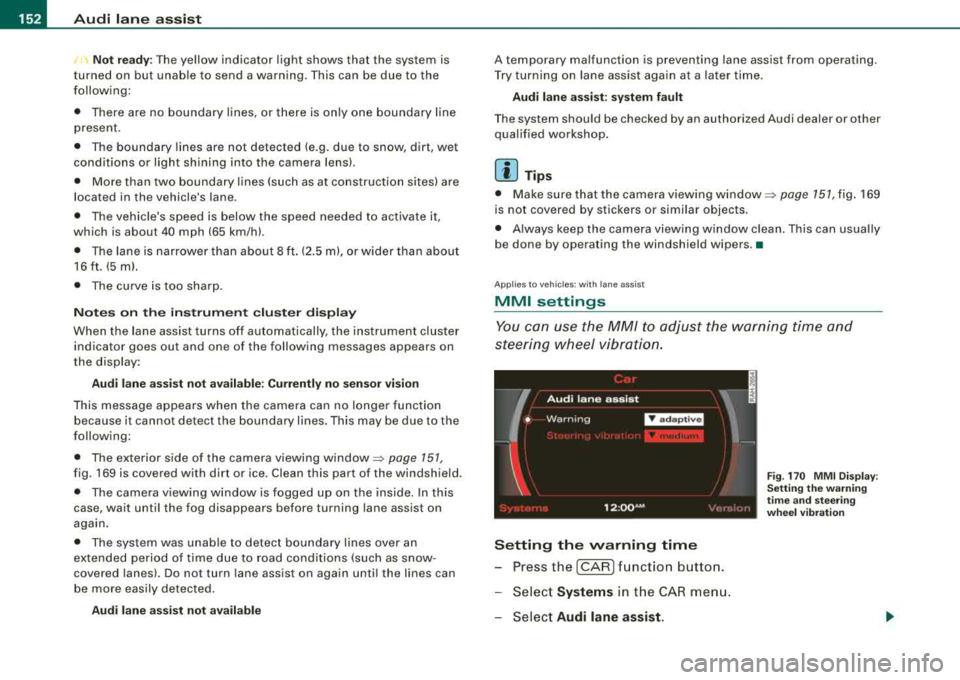
You can use the MM/ to adjust the warning time and
steering wheel vibration.
Setting the warning time
- Press the [CAR ] function button.
- Select
Systems in the CAR men u.
- Select
Audi l ane ass is t.
Fig . 17 0 M MI D isp lay :
Se ttin g th e w arning
t im e a nd stee ring
w hee l v ibr ati on
Page 161 of 404
___________________________________________________ A_u_ d_i_ s_ id_e_ a_ s_s _i_s _t _ __.ffllll
Ap plies to vehi cles: w ith side ass is t
Driving situation: Vehicles dropping back
quickly
Fig . 178 Side assist: Vehicles dropping back quickly
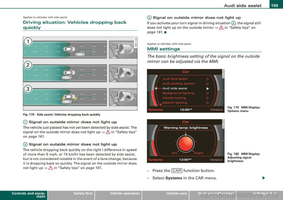
0 Signal on outside mirror does not light up
The vehicle just passed has not yet been detected by side assist. The
signal on the ou tside mirror does not light
up => & in "Safety tips"
on
page 161 .
@ Signal on outside mirror does not light up
The vehicle dropping back quickly on the right ( difference in speed
of more than 9 mph , or 15 km/h) has been detected by side assis t,
but is not considered notable in the event of a lane change, because
it is dropping back so quick ly . The signal on the outside mirror does
not light
up => & in "Safety tips " on page 161.
Controls and equip
ment
G) Signal on outside mirror does not light up
If you activate your turn signal in driving situation @, the signal still
does not ligh t up on the outside
mirror=> & in "Safety tips" on
page 161. •
Applies to veh ic les: w it h side ass ist
MMI settings
The basic brightness setting of the signal on the outside
mirror can be adjusted via the MM/.
I
W arn in g lam p: brightn ess
' •
12 :oo~M • <: ''·,.I,,
Press the [CAR ] function button.
Select
Systems i n the CAR menu.
Vehicle care I I
-
Fig . 179 MMI Display :
Options menu
Fig . 180 MMI Display :
Adjusting signal
brightness
irechnical data
Page 162 of 404
___ A_ u_ d_ i_s _i_d _e_ a_ s_ s
_ is_ t __________________________________________________ _
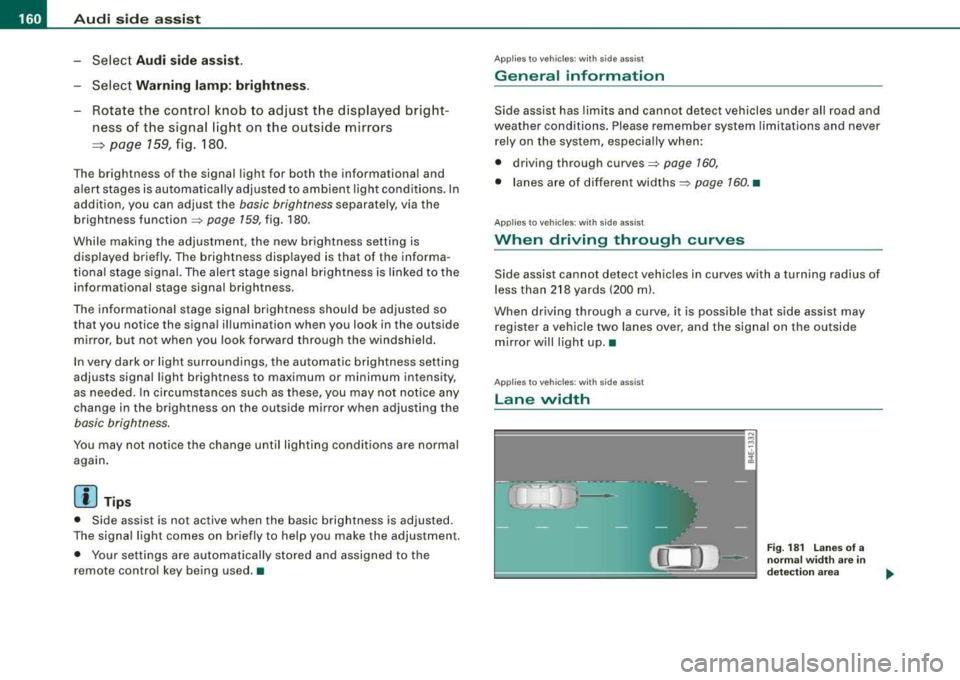
-Select Audi sid e ass is t.
-Select W arning l amp : brightn ess.
-Rotate the control knob to adjust the displayed bright -
ness of the signal l ight on the outside mirrors
=> page 159, fig. 180 .
Th e brightn ess o f th e signal light for both th e informational and
a lert stages is automatica lly adj usted to ambient light conditions. In
addition, you can adjust the
basic brightness separately, via the
brightness function
=> page 159, f ig. 180.
While mak ing the adjustment , the new br ig htness setting is
displayed briefly. The brightn ess disp layed is that of the informa
tiona l stage s ignal. The alert stage signal brightness is linked to the
in formational stag e signal brightness .
The infor mationa l stage signal br ightness should be adjusted so
that you notice the signa l illumination when you look in the outside
m irror, but not when you look forward through the windsh ield.
In very dark or light surround ings , the automat ic brightness setting
adjusts signal light brightness to maximum or minimum intensity ,
as needed . In circumstances such as these, you may not not ice any
change in the brightness on the outside m irror wh en adjusting the
basic brightness .
You may not notice the change until ligh ting conditions are normal
aga in .
[ i ] Tip s
• Side assist is not active wh en the basic brightness is adjusted .
The signal l ight comes on briefly to help you make the adjustment.
• Your settings are automatically s tored and assigned to the
remote contro l key being used. •
App lies to ve hicles: w ith s ide assis t
General information
Side assist has lim its and cannot detect vehicles under all road and
weather conditions. Please remember system limit ations and never
rely on the system, especia lly when:
• driving through
curves=> page 160,
• l anes are of different widths => page 160. •
Applies to ve hicles : w ith sid e as sist
When driving through curves
Side assist cannot detect vehic les in curves with a turning radius of
l ess than
218 yards (200 m) .
When driving through a curve , it is poss ib le that side assist may
register a vehicl e two lanes over, and the signal on the outside
m irror w ill light up .•
A pplies to vehicle s: w ith sid e ass is t
Lane width
w cl,
Fig . 18 1 L an es of a
norma l widt h are i n
d etec tion area
Page 163 of 404
_________________________________________________ A
_ u_ d_ i _s _ i_d _e _ a_s_ s_ i_ s _t __ lJIII
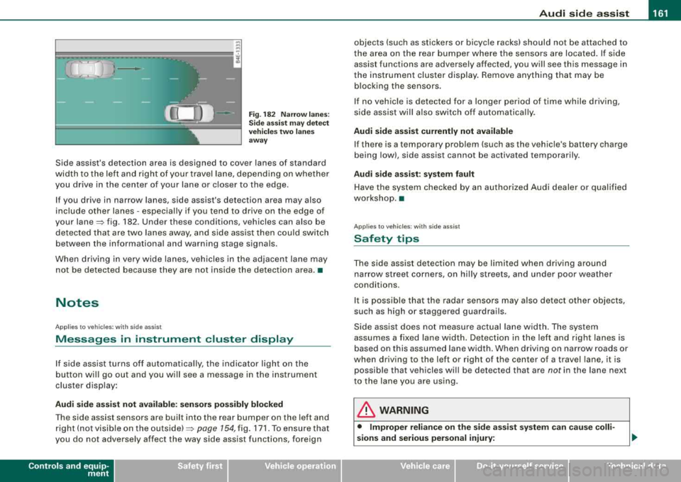
Fig . 182 Narr ow lane s:
Si de ass is t m ay detec t
vehi cle s two la ne s
a w ay
Side assist's detection area is designed to cover lanes of standard
width to the left and r ight of your travel lane, depend ing on whethe r
you drive in the center of your lane or c loser to the edge .
I f you drive in narrow lanes, side assist's detection area may also
include other lanes - especially if you tend to dr ive on the edge of
your
lane~ fig . 182. Under these conditions, vehicles can also be
de tec ted tha t are two lanes away, and side ass ist then c ould switch
between the informational and warning stage signa ls.
When d riving in very wide lanes, vehicles in t he adjacent lane may
not be detected because they are not ins ide the detection area. •
Notes
Applies to vehicles: with side ass is t
Messages in instrument cluster display
If side assist turns off automatically, the indicator light on the
b utton wil l go out a nd you w ill see a message in the i nstrument
cluster disp lay :
Audi side a ssist not available : sen sor s pos sibly blocked
T he side assist sensors are bui lt into the rear bumper on the left and
r ight ( not visi ble on the
ou ts id e) ~ page 154, fig. 171 . To ensure t hat
you do not adverse ly affect the way side assist functions, foreign
Controls and equip
ment
objects (such as stickers or bicyc le racks) should not be attached to
t he area on the rear bumper where the sens ors are loca ted. If s ide
assist functions are adversely affected, you will see this message in
the instrument cluster display. Remove anything that may be b locking the sensors .
I f no vehic le is detected for a longer period of time while driving,
s ide assist wil l also switch o ff automatica lly.
Audi side a ssist currently not available
If there is a temporary prob lem (such as the vehic le's battery charge
being low), side assist cannot be activated temporarily .
Audi side assis t : sy stem fault
Have t he system chec ked by an autho rized Audi dealer o r qualified
workshop. •
Applies to vehic les: with side assist
Safety tips
The side ass ist detec tion may be li mit ed when dr iv ing a round
narrow street corners, on hilly streets, and under poor weather
conditions.
I t is possible that the radar sensors may a ls o detec t other objects,
such as high or staggered guardrails.
Side ass ist does not measu re actual la ne w idth. The system
assumes a fixed lane width. Detection in the left and right lanes is
based on this assumed lane width. When driving on narrow roads or
when driv ing to the left or right of the center of a travel lane, it is
possible that vehicles wi ll be detected that are
not in the lane next
to the lane you are using.
& WARNING
• Improper relian ce on the side assi st system c an cau se colli
sions and serious personal injury:
Page 169 of 404
_______________________________________________ A_ u_t _o _m_ a_ t_ i_ c _ t_r _
a _n _s_ m_ i_ s _ s_ i_ o _ n _ ___._
gear when the driver presses the brake pedal on a downhill
gradient. This makes use of the braking effect of the engine without
the need to shift down manually. •
Manual shift program
Using the manual shift program you can manually select
gears.
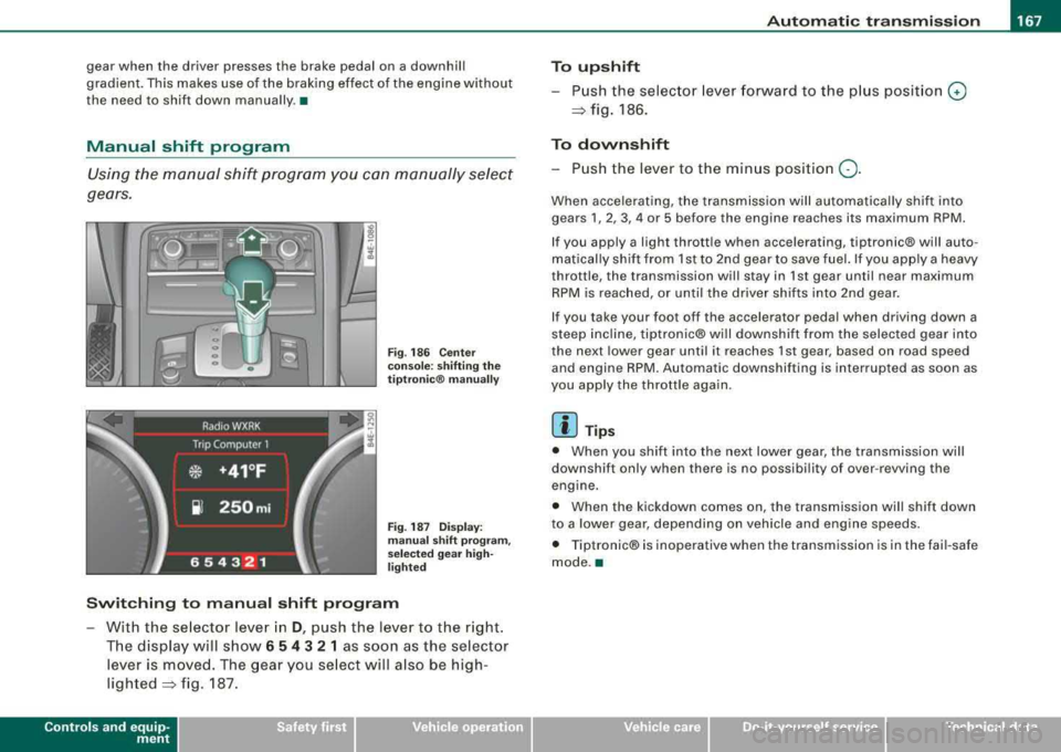
Fi g. 186 Center
console: shifting the
tiptr onic ® manually
Fig. 187 Display:
man ual shift pr ogra m ,
selected gear high
li ghted
Switching to manual shift program
With the se lector lever in D, push the lever to the right.
The display will show
6 5 4 3 2 1 as soon as the selector
lever is
moved. The gear you select will also be high
lighted~ fig. 187.
Controls a nd eq uip
ment
To upshift
Push the selector lever forward to the plu s position 0
~ fig. 186.
To downshift
- Push the lever to the minus position Q.
When accelerating, the transmission will automatically shift into
gears
1, 2, 3, 4 or 5 before the engine reaches its maximum RPM.
If you apply a light thrott le when accelerating, tiptronic® will auto
matically shift from 1st to 2nd gear to save fuel. If you app ly a heavy
throttle, the transmission will stay in 1st gear until near maximum
RPM is reached, or until the driver shifts into 2nd gear.
If you take your foot off the accelerator peda l when driving down a
steep inc line, tiptronic® wi ll downshift from the selected gear into
the next lower gear until it reaches 1st gear, based on road speed
and engine RPM. Automatic downshifting is interrupted as soon as
you apply the throttle again.
[ i ] Tips
• When you shift into the next lower gear, the transmission will
downshift only when there is no possibi lity of over -revving the
engine.
• When the kickdown comes on, the transmission will shift down
to a lower gear, depending on vehicle and eng ine speeds.
• Tiptronic® is inoperative when the transmission is in the fai l-safe
mode .•
Vehicle care I I irechnical data