AUDI S8 2014 Owners Manual
Manufacturer: AUDI, Model Year: 2014, Model line: S8, Model: AUDI S8 2014Pages: 314, PDF Size: 78.47 MB
Page 121 of 314
prevent the vehicle from "creeping", you
must keep your foot on the brake in all
selector lever positions except P and N
when the eng ine is running . Do not inad
vertently press the accelerator pedal
when the veh icle is stationary . Otherwise
the vehi cle will s tart to move immediate
ly, even if the park ing brake is set. This
cou ld result in a crash.
- Do not ride the brakes or p ress the brake
peda l too often or too long when dr iv ing
down a hill. Constant braking causes the
brakes to overheat and substant ially re
duces b raking performance, increases
braking distance or ca uses comp lete fail
ure of the brake system.
Hill descent control
The hill descent control system assists the
driver when driving down declines.
H ill descent control is activated when these
lector lever is in D/S and you press the brake
pedal. The transmission automatically se lects
a gear that is suitab le for the incline . Hill de
scent control tries to maintain the speed ach ieved at the time of brak ing, within physical
a nd techn ical limitations.
It may st ill be nec
essary to adjust the speed with the brakes.
H ill descent control switches off once the de
cline levels out or you press the accelerator
pedal.
Hill descent control is also activated when the
speed is set by starting the cru ise contro l sys
tem
r:::;, page 91.
A WARNING
H ill descent control can not overcome
phys ical limitations, so it may not be able
to main tain a constant speed under a ll
condi tions. Always be re ady to app ly the
br akes.
Automatic Tra nsmi ssi on 119
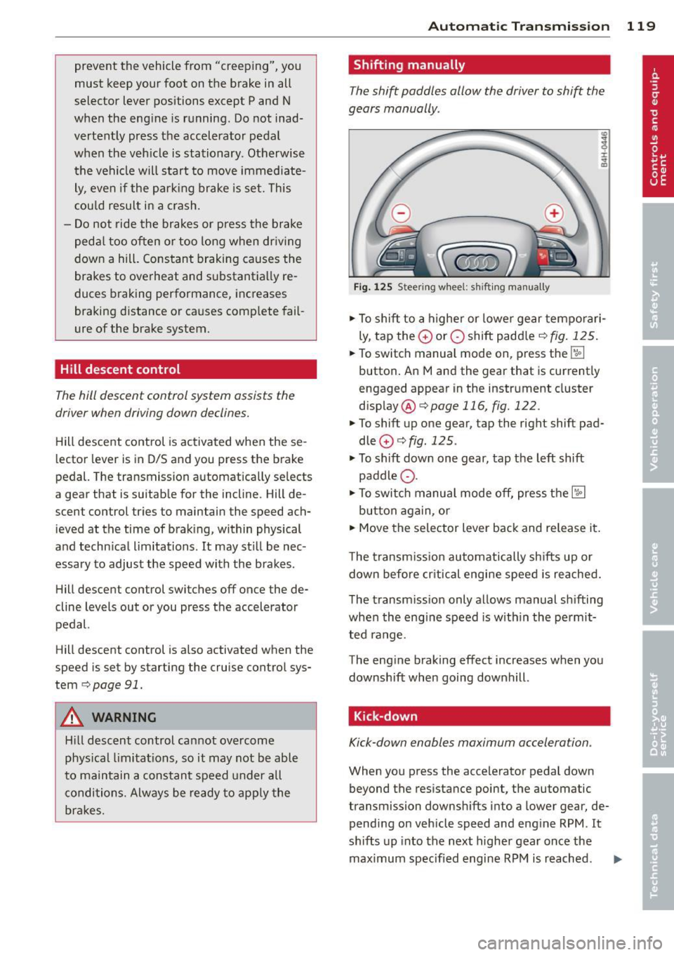
Shifting manually
The shift paddles allow the driver to shift the
gears manually .
Fig . 12 5 Steer ing w hee l: s hifting manually
.,.. To shift to a h igher or lowe r gear tempo rari
ly, tap the
0 or 0 shift paddler:::;, fig. 125 .
.. To switch manua l mode on, press the~
button . An Mand the gear that is currently
engaged appear in the inst rument cluster
disp lay @ ¢
page 116, fig. 122.
.. To shift up one gear, tap the righ t shift pad
dle
0 r:::;, fig . 125 .
.. To sh ift down one gear, tap the left shift
paddle Q.
.. To switc h manua l mode off, press the~
button aga in, or
.. Move the selector lever back and release it .
T he transm iss ion automatically sh ifts up or
down before cr itical engine speed is reached.
The transm iss ion only allows manual sh ifting
whe n the eng ine speed is w ith in the pe rmit
ted range .
The eng ine braking effect increases when you
downshift when going downhill .
Kick-down
Kick-down enables maximum acceleration .
When you press the accelerator pedal down
beyond the resistance point, the automatic
transmission downsh ifts into a lower gear, de
pending on veh icle speed and eng ine RPM .
It
shifts up into the next higher gear once the
maximum specified engine RPM is reached . ..,.
Page 122 of 314
![AUDI S8 2014 Owners Manual 120 Automatic Transmission
8_ WARNING
Please note that the wheels could spin on
slick or slippery roads when kick-down is
active .
Transmission malfunction
[O] Transmission: plea se AUDI S8 2014 Owners Manual 120 Automatic Transmission
8_ WARNING
Please note that the wheels could spin on
slick or slippery roads when kick-down is
active .
Transmission malfunction
[O] Transmission: plea se](/img/6/57613/w960_57613-121.png)
120 Automatic Transmission
8_ WARNING
Please note that the wheels could spin on
slick or slippery roads when kick-down is
active .
Transmission malfunction
[O] Transmission: plea se press the brake ped
al and select the position again
Press the brake pedal and select the des ired
selector lever posit ion again . You can then
continue dr iving .
[O] Transmission hot: please modify driving
style
The transmission temperature has increased
significantly due to the sporty driving manner.
Drive in a less sporty manner until the tem
perature returns to the normal range and the
indicator light switches of.
[O] Gearbox malfunction: you can continue
driving
There is a system ma lfunction in the transmis
sion. You may continue driving. Drive to your
authorized Audi dealer or qualified repair fa
cility soon to have the malfunction corrected.
l'i]Jffl Gearbox malfunction: you can contin
ue driving in D only until engine is off
There is a system ma lfunction in the transmis
sion. The transmission is switching to emer
gency mode. If you turn the engine off, you
will not be able to select any other selector
lever positions after starting the engine again.
Drive to your authorized Aud i dealer or quali
fied repair facility immediately to have the
malfunction corrected.
[O] Gearbox malfunction: you can continue
driving (limited functionality)
There is a system ma lf u nction in the transmis
sion. The transmission is switching to emer
gency mode. Th is mode only shifts into cer
tain gears or will not longer shift at all. The
engine may stall. Dr ive to your authorized
Aud i dealer or qualified repair facility immedi
ately to have the malfunction corrected.
[O]/jj'j Gearbox malfunction: no reverse gear
(y ou can continue driving)
The re is a system malfunction in the transmis
s ion. The transm ission is swi tching to emer
gency mode. This mode on ly shifts into cer
tain gears or will not longer shift at al l. You
cannot engage the reverse gear . Dr ive to your
authorized Aud i dea ler immediately to have
the malfunction corrected.
[O] Vehicle may roll! Cannot shift to P. Please
apply parking brake
-The parking lock was re leased using the
emergency release
¢page 121. Or
- The parking brake cannot engage automati
cally. Drive to your authorized Audi dea ler or
qualified repair facility immediately to have
the malfunction corrected.
[O] Gearbox malfunction: Stop and shift to P
Do not continue dr iving . Select the P selector
lever position and see your author ized A udi
dealer or qualified repair faci lity for assis
tance.
Page 123 of 314
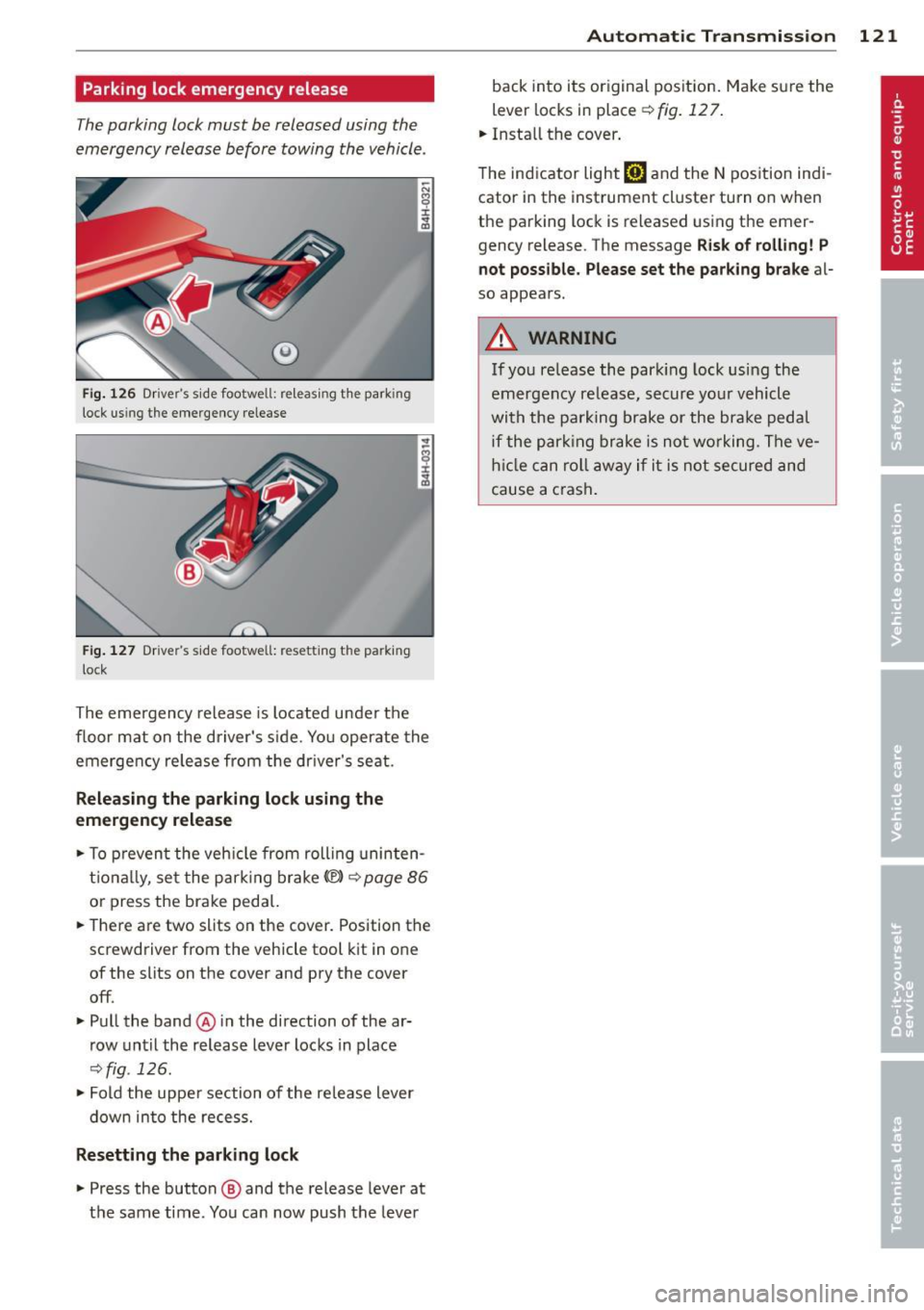
Parking lock emergency release
The parking lock must be released using the
emergency release before towing the vehicle .
®
Fig. 126 Driver's s ide footwell: re lea sing t he park ing
lock us ing the emergency release
Fig. 127 Drive r's s ide footwell: resettin g th e pa rk ing
lock
The emergency release is located under the
f loor mat on the driver's s ide. You operate the
emergency re lease from the driver's seat.
Releasing the parking lock using the
emergency release
.,. To prevent the vehicle from rolling uninten
tionally, set the parking brake
«e)) q page 86
or press the brake peda l.
.,. There are two slits on the cover. Position the
screwdriver from the vehicle tool kit in one
of the slits on the cover and pry the cover
off .
.,. Pull the band@ in the direction of the ar
row until the release lever locks in place
qfig . 126 .
.,. Fold the uppe r section of the re lease lever
down into the recess.
Resetting the parking lock
.,. Press the button @ and the release lever at
t h e same time. You can now push the lever
Automatic Transmission 121
back into its original position. Make sure the
lever locks in place ~
fig. 12 7.
.,. Install the cover .
T he indicator light
[O] and the N position indi
cator in the instrument cluster turn on when
the parking lock is released using the emer
gency release. The message
Risk of rolling! P
not possible. Please set the parking brake
al
so appears .
.&_ WARNING
If you release the park ing lock using the
emergency release, secure your vehicle
with the parking brake or the brake pedal
i f the parking brake is not working. The ve
hicle can roll away if it is not secured and
cause a crash .
Page 124 of 314

122 Parking system s
Parking systems
General information
Applies to vehicles: with parking system plus/rear view
camera/peripheral cameras
Depending on your vehicle's equ ipment, vari
ous parking a ids wi ll help yo u when pa rk ing
and maneuve ring.
The
advanc ed park ing sy stem with r ear vi ew
cam era
ass ists you when parking by aud ibly
and v isua lly indicating objects detected
in
front of
and behind the veh icle. The rear view
camera shows the area behind the vehicle i n
the Infotainment disp lay. This disp lay assists
you when you are cross or parallel parking
co page 123.
The peripheral camera s assist yo u with pa rk
ing and maneuvering . You are aided by various
cameras depending on the vehicle equipment
leve l
co page 127. In add it ion, you are assist
ed by the functions from the sensors
co page 123, Sensors, co page 125, Visual
display.
A WARNING
- Always look fo r traff ic and check the area
around you r vehicle by looking at it di
rect ly as we ll. The parking sys tem canno t
rep lace t he drive r's a ttent ion. The dr iver
is a lways respons ible for safety during
par king and for all other maneuvers.
- Please note tha t some sur faces, such as
clothing, are not detected by the system .
- Sensors and cameras have blind spots in
wh ich peop le and objects cannot be de
tected . Be especially cautious of children
and animals.
- The sensors can be displaced by impacts or damage to t he radiato r grille, bumpe r,
wheel housing and the underbody. The park ing systems may become impaired
as a result. Have your authorized Audi
dealer or qualified workshop check their
f unction.
- Make sure the sensors are not covered by
stickers, deposits or any othe r obstruc
t ions as it may impair the senso r func- tion. Fo
r informat ion on cleaning, refe r
to
co page 216.
@ Note
- Some objects are not detected by the
system under certain ci rcumstances:
- Objects such as barrie r chains, trailer
draw bars, vertical poles or fe nces
- Objects above the sensors such as wall
extensions
- Objects w ith specific surfaces or struc
tures such as chain link fences or pow
de r snow.
- If you conti nue driving closer to a low- ly
ing object, it may disappea r from the
sensor range. Note that you w ill no lon
ger be warned about this obstacle.
0) Tips
- The system may provide a warning even
tho ugh there are no obstacles in the cov
erage a rea in some situations, such as:
- certain road s urfaces or for long grass .
- ex terna l ult raso nic sources e.g. from
cleaning vehi cles.
- h eavy ra in, s now or thick ve hicle ex
ha ust.
- We recommend tha t yo u pr actice park
ing in a t raff ic-free loca tion or par king
lot to become familiar w it h the system.
Whe n doi ng this, the re should be good
light and weathe r cond itions.
- Yo u can change the vo lume and pitch of
the s ignals as we ll as the disp lay
co page 132.
-Please refer to the instr uctions for tow
ing a t railer
co page 132.
-W hat appea rs in the infotainment dis
play is somewhat time-delayed.
Page 125 of 314

Advanced parking system with rear view
camera
Introduction
Applies to vehicles: with advanced park ing system with
rear vi ew camera
Fig. 128 Illustrat ion : C ross pa rki ng
Fig. 129 Illust ration: paralle l park ing
(0
s ± ., CD
Vehicles w ith the park ing system advanced
are equ ipped w ith a rear view camera in addi
tion to the acoustic and visua l park ing system.
You can use
cross parking for example, to
park in a parking space or in a garage
r::!:> fig . 128 . You can use parallel parking if you
wou ld like to park on the side of the road
r::!:> fig. 129 .
Parking systems 123
General information
Applies to vehicles: with advanced parking system with
rear view camera
Fig. 130 Area covered (!)and area not covered @by
t he rear view ca mera
A U Dl
Fig. 131 Rea r lid : Locat ion o f the rear vi ew ca mera
Sensors
Sensors are located in the front and rear
bumpers . If these detect an obstacle , visua l
and in some situations audible signals warn
you .
Make sure the sensors are not covered by
stickers, deposits or any other obstructions as
it may impair the sensor function. For infor
mation on cleaning, ref er to r::!:>
page 216.
The display field begins approximately at:
side
front 3
ft (0.90 m)
center 4
ft (1.20
m)
s ide 2
ft (0.60 m)
rear
center 5.2
ft (1.60 m)
T
he closer you get to the obstacle, the shorter
the interval between the audible signals . A
continuous tone sounds when the obstacle is
less than approximately 1
ft (0.30 m) away.
Do not continue driving farther
r::!:> .&. in Gener
al information on page 122,
c> (D in General
information on page
122!
Page 126 of 314
124 Parking systems
If the distance to an obstacle remains con
stant, the volume of the distance warning
gradually drops after about four seconds (this
does not apply in the continuous tone range).
Rear view camera
The rear view camera is located above the rear
license plate bracket. Make sure that the lens
for the parking system¢
fig. 131 is not cov
ered by deposits or any other obstructions be
cause this can affect the function of the park
ing system. For information on cleaning, refer
to
¢ page 216.
The rear view camera coverage area includes
(D ¢ fig. 130. Only this area is shown in the
Infotainment display. Objects that are outside
of this area@are not displayed.
The accuracy of the orientation lines and the blue surfaces is reduced if the adaptive air
suspension" is faulty, if the vehicle is lifted or
if the
dynamic mode is activated¢ page 110.
A WARNING
-Always read and follow the applicable
warnings¢ .&.
in General information on
page 122.
- If the position and the installation angle
of the rear view camera was changed, for
example, after a collision, do not contin
ue to use the system for safety reasons.
Have it checked by your authorized Audi
dealership or authorized repair facility.
- Only use the rear view camera to assist
you if it shows a good, clear picture. For
example, the image may be affected by
the sun shining into the lens, dirt on the
lens or if there is a system fault.
- Use the rear view camera only if the lug
gage compartment lid is completely
closed. Make sure any objects you may
have mounted on the luggage compart
ment lid do not block the rear view cam
era .
- The camera lens enlarges and distorts
the field of vision. The object appears both altered and inaccurate on the
screen. -
In certain situations, people or objects in
the display appear closer or further
away:
- objects that do not touch the ground,
such as the bumper of a parked vehicle,
a trailer hitch or the rear of a truck. Do
not use the help lines in this case.
- If driven from a level surface onto an
incline, or a downward slope.
- If driven toward protruding objects.
-If the vehicle is carrying too much load
in the rear.
{[) Note
-Always read and follow the applicable
warnings
c::> (D in General information on
page 122.
- The orange colored orientation lines in
the Infotainment display show the vehi
cle path depending on the steering
wheel angle. The front of the vehicle
front swings out more than the rear of
the vehicle. Maintain plenty of distance
so that your outside mirror or a corner of
your vehicle does not collide with any ob stacles.
Page 127 of 314
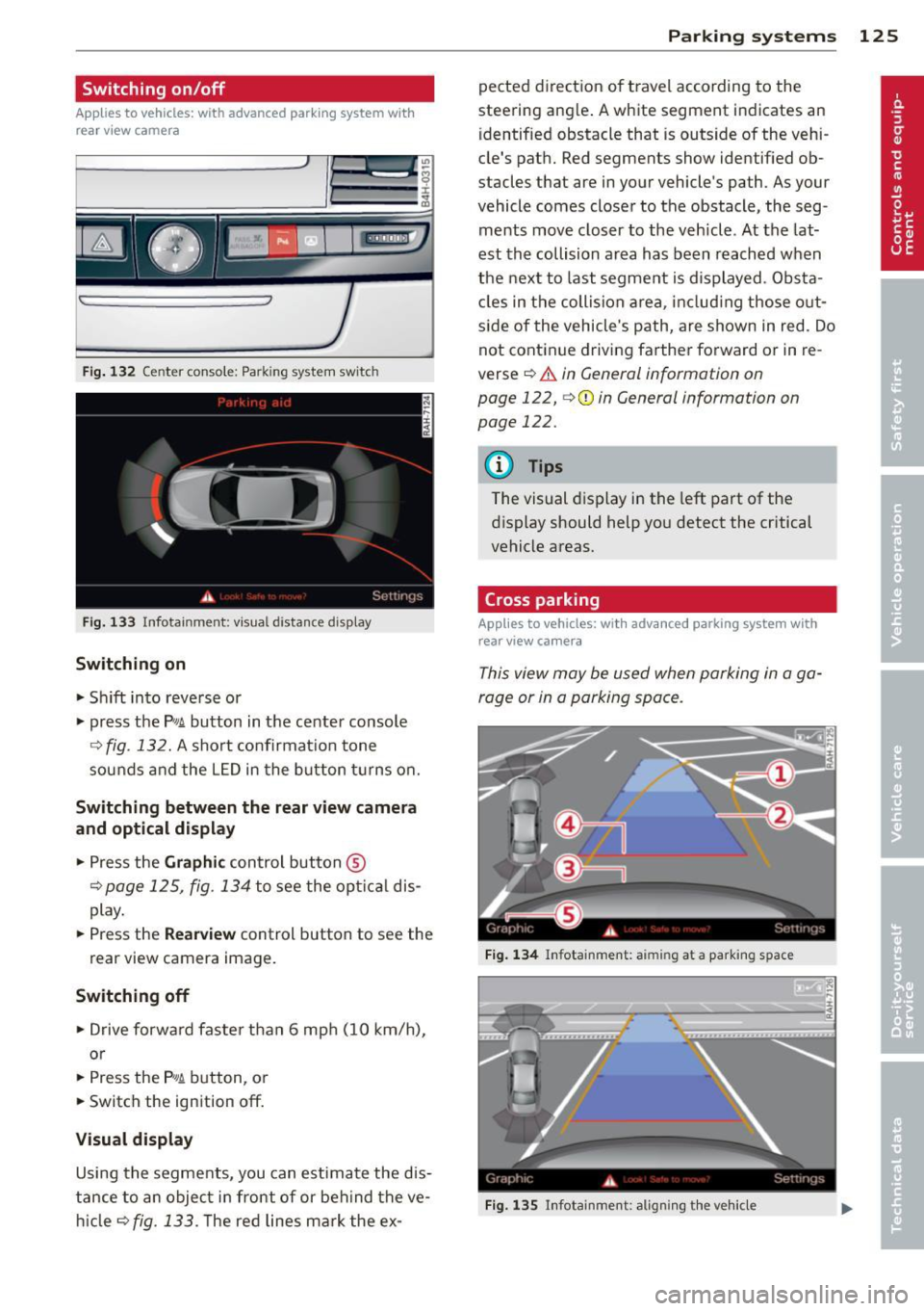
Switching on/off
Applies to vehicles: with advanced park ing system wit h
rear view camera
Fig. 132 Center console: Park ing system switc h
Fig. 133 Infotainment: visual distance display
Switching on
.,. Sh ift into reverse or
.,. press the
P,#! button in the center console
Q fig. 132. A short confirmat io n tone
sounds and the L ED in the b utton tu rns on.
Switching betwe en the rear view camera
and opt ical displ ay
.,. Press the Gr aph ic control button ®
¢page 125, fig . 134 to see the opt ica l dis
play .
.,. Press the
Rear view control button to see the
rear view camera image.
Switching off
.,. Drive forward faster than 6 mph (10 km/h),
or
.,. Press the
P,#! button, o r
.,. Switch the ignition
off.
Visual display
Using the segme nts, you can estimate the d is
tance to an object in front of or beh ind the ve
hi cle
Q fig . 133. T he red lines mark the ex -
Parking sys tems 125
pected direction of travel according to the
steering angle . A white segment indicates an
identified obstacle that is outside of the vehi
cle's path. Red segments show identif ied ob
stacles that are in your vehicle's path. As your
vehicle comes closer to the obstacle, the seg
ments move closer to the veh icle . At the lat
est th e collision area has been reached when
the next to last segme nt is displayed . Obs ta
cl es in the collision a rea, includ ing those o ut
s ide of the vehicle's path, are shown in red. Do
not continue driving farthe r forward or in re
verse
¢ .&. in General information on
page 122,
¢ 0 in General information on
page 122.
{!) Tips
The visual display in the left part of the
display should help you detect the critical
vehicle areas.
Cross parking
App lies to vehicles: wit h advanced parking system w ith
rear view ca mera
This view may be used when parking in a ga
rage or in a parking space .
Fi g. 13 4 Infota inment: aiming at a parking space
Fig. 135 In fotainment: a lig nin g the ve hicle
Page 128 of 314
126 Parking systems
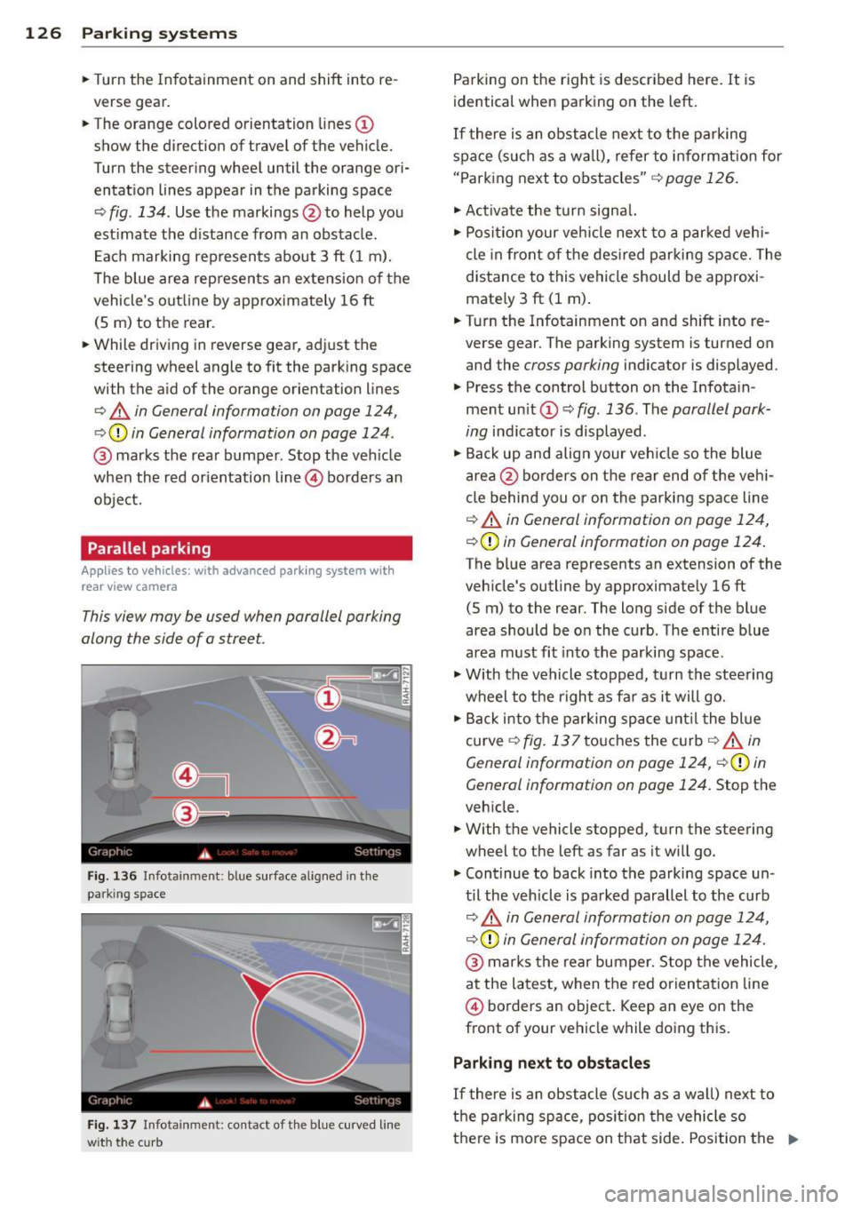
• Turn the Infotainment on and shift into re
verse gear.
• The orange colored orientation lines @
show the direction of travel of the vehicle.
Turn the steering wheel until the orange ori
entat io n lines appear in the parking space
Q fig . 134. Use t he markings @to help you
est ima te the d istance from an obstacle .
E ac h marking represents about 3 ft ( 1 m).
T he blue area rep resents an extension of the
vehicle 's outline by ap proximately 16 ft
(S m) to the rear.
• While driving in reverse gear, adj ust the
steering wheel angle to fit the park ing space
with the a id of the orange orientation lines
Q .&, in General information on page 124,
Q Q) in General information on page 124 .
@ marks the rear bumper. Stop the ve hicle
when the red orientation line@ borders an
obje ct.
Parallel parking
Applies to vehicles: with advanced park ing system with
rear view camera
This view may be used when parallel parking
along the side of a stree t.
Fig. 136 Infota inment: bl ue s urface aligne d in the
park ing sp ac e
Fig . 137 In fota inm ent: c on ta ct of t he blue curved line
wit h the c urb
Parking on the right is described here. It is
identical when parking on the left.
If there is an obstacle next to the parking
space (such as a wall), refer to i nformat ion for
" P ark ing next to obstacles"
Q page 126.
• Activa te the turn signa l.
• Posi tion your veh icle next to a parked veh i
cle in front of the des ired parki ng space. The
distance to this vehicle should be approxi
mate ly 3 ft (1 m) .
• Turn the Infotainment on and shift into re
verse gear . The parking system is tu rned on
and the
cross parking indicator is displayed .
• Press the control button o n the Infota in
ment unit @ c::,
fig. 136. The parallel park
ing
indicator is displayed .
• Ba ck up and align your veh icle so the blue
area @borders on the rear end o f th e veh i
cle behind you or on the parki ng space line
Q .&, in General information on page 124,
c::, Q) in General information on page 124 .
The blue area represents an extension of the
veh icle 's outline by approximate ly 16 ft
(S m) to the rear. The long side of the blue
area should be o n the curb . The entire blue
area m ust fit into the parking space .
• With the vehicle stopped, t urn the stee ring
wheel to t he right as fa r as it will go.
• Back i nto the p arking space unt il t he blue
curve
c::, fig. 137 touches the c urb c::, _&, in
General information on page 124,
c::, Q) in
General information on page 124.
Stop the
veh icle.
• With the vehicle stopped, turn the steering
wheel to the left as far as it w ill go.
• Cont inue to back into the parking space un
til the veh icle is parked parallel to the curb
i:::> .&, in G en eral information on pag e 124,
c::, Q) in General information on page 124.
@ marks the rear bumper. S top the vehicle,
at the latest, when the red orien tati on line
@ borders an object . Keep an eye on the
front of your vehicle while doing this.
Parking next to obstacles
If there is an obstacle (such as a w all) next to
the parking space, pos ition the vehicle so
there is mo re space on that side. Position the .,..
Page 129 of 314

long side of the blue surface so that there is
suff icient space from the obstacle. The sur
face must not be touch ing. You will also need
to start turning the steer ing whee l much ear
lier. The blue curve
¢ fig . 13 7 must not to uch
the obstacle and should have sufficient room .
@ Tips
The left or right orientation lines and sur
faces will be displayed, depend ing on the
turn signa l bei ng used.
Peripheral cameras
Introduction
Applies to vehicles: with top view camera system
In addit ion to the functions from the sensors
¢ page 123, Sensors,¢ page 125 , Visual dis
play,
this parking system conta ins peripheral
cameras. Depending on the ve hicle equip
ment, you are assis ted by various views such
as peripheral view, corner views at the front
and rear of the veh icle, and views d irectly in
fro nt of o r behind the vehicle.
General information
App lies to vehicles: with top view camera system
Fig. 138 Loca tion of per ipheral came ras
Depending on the vehicle equ ipment, the pe
riphera l cameras are fou nd i n the radiator
grille, in the luggage compartment lid and on both exterior mirrors ¢
fig. 138 . Make sure
that the lenses are no t covered by deposits or
any other obstructions as it may impair the
sys tem. For information on cleaning, refer to
¢ page 216.
P arking sys tems 127
In the to p view mode, b lack corners are
shown in the ve hicle silhouette . Objects in
these areas are outside of the camera 's field
of view and are not detected .
T he accuracy of the orientation lines and the
bl ue surfaces is reduced if the adaptive air
suspension * is faulty, if the vehicle is lifted or
if the
dynamic mode is activated ¢ page 110.
A WARNING
- Always read and follow the applicable
warn ings ¢
& in General information on
page 122.
- If the position or the installat io n angle
of a camera was changed , after a colli
sion for example, do not continue to use
the system fo r safety reaso ns. Have i t
checked by you r author ized Audi dealer
sh ip .
- Keep in mind tha t the image in the dis
pl ay is distorte d if the exterior mirror
housing has bee n manually a dju sted .
- Use the
rear mode and the c orner view
( rear )
mode only when the luggage com
partment lid is fu lly closed . Otherwise
the image in the disp lay will be d istort
ed .
- T he vehicle surro undings are shown us
ing the came ra images. The veh icle im
age is shown by the system. Objects and
obstacles above the camera are not d is
p layed.
- Camera lenses enlarge and distort the fie ld of vision . T he objects appear both
altered and inaccurate on the sc reen.
(D Note
- Always read and follow the ap plicable
warnings
¢(Din General information on
page 122.
- The Infotainment d isp lay shows the di
rection in which the rear of the vehicle is
traveling based on the steer ing whee l
ang le . The front of the vehicle front
swings out more than the rear of the ve
hicle . Maintain plenty of d istance so that
IJJ,,
Page 130 of 314
128 Parking systems
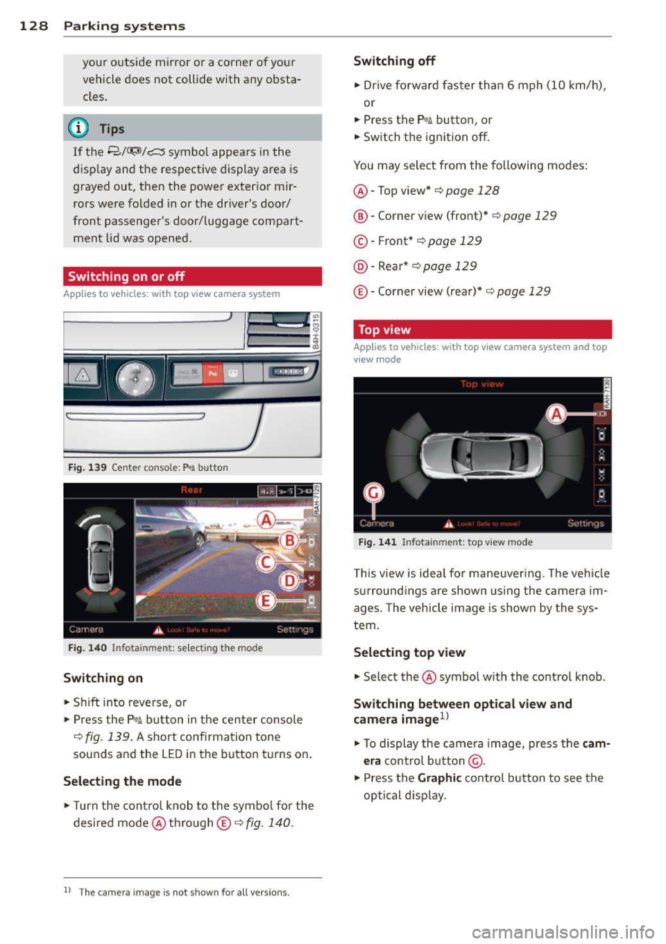
your outside mirror or a corner of your
vehicle does not collide with any obsta
cles.
@ Tips
If the 8/o;iJ/c:::::5 symbol appears in the
disp lay and the respectiv e display area is
grayed out, then the power exter ior mir
rors were folded in or the dr iver's door/
front passenger's door/luggage compart
ment lid was opened.
Switching on or off
App lies to vehicles: with top view camera system
Fi g. 139 Center consol e: P
Switching on
• Shift in to reve rse, or
> Press the P, qi b utton in the center console
¢
fig . 139 . A short confirmat ion tone
sounds and the LED in the button turns on .
Selecting the mode
• Turn the contro l knob to the symbol for the
desired mode @thro ugh
© ¢fig. 140.
ll Th e c am era im age is n ot s hown fo r all ve rsi on s.
Switching off
• Dr ive fo rward faster than 6 mph (10 km/ h),
or
• Press the
P, JJi button, or
• Switch the ignition off .
You may select from the following modes:
@ -Top view* ¢
page 128
@-Corner view (front)* ¢ page 129
© -Front * ¢ page 129
@ -Rea r* ¢
page 129
© -Corner view (rear)* ¢ page 129
Top view
Applies to vehicles : w it h top v iew camera system and top
v iew mode
F ig . 14 1 In fota inm ent : top v iew m ode
This view is idea l for maneuver ing. The veh icle
surround ings a re shown us ing the camera im
ages . The vehicle image is shown by the sys
tem.
Selecting top view
"' Select the@symbo l w ith th e control knob .
Switching between optical view and
camera imagel)
"'To display the came ra image, press the c am
era
control button @.
"' Press the
Graphi c control button to see the
optical d isp lay.