AUDI TT 1999 8N / 1.G AEB ATW Engines Vacuum Control System Workshop Manual
Manufacturer: AUDI, Model Year: 1999,
Model line: TT,
Model: AUDI TT 1999 8N / 1.G
Pages: 8, PDF Size: 0.06 MB
AUDI TT 1999 8N / 1.G AEB ATW Engines Vacuum Control System Workshop Manual
TT 1999 8N / 1.G
AUDI
AUDI
https://www.carmanualsonline.info/img/6/959/w960_959-0.png
AUDI TT 1999 8N / 1.G AEB ATW Engines Vacuum Control System Workshop Manual
Trending: brake light, fuel pressure, fuel, airbag, brake, gas type, fuel pump
Page 1 of 8
21-38
Vacuum control system
(engine code ATW)
Notes:
Observe rules for cleanliness Page 21
-39
Observe safety precautions Page 21
-40
Always replace gaskets, O-rings and self-
locking nuts and bolts.
Secure all hose connections using original
equipment type hose clamps:
Parts catalog
Before performing a test or repair, check all
hoses and wires for proper seating and seal.
Pa
ge 1 of 8 Vacuum control s
ystem
(en
gine code ATW
)
11/18/2002 htt
p://127.0.0.1:8080/audi/servlet/Dis
play?action=Goto&t
yp
e=re
pair&id=AUDI.B5.GE02.21.2
Page 2 of 8
21-39
Rules of cleanliness
When working on the vacuum control system,
charge air pressure regulation or at the
secondary air system hoses, always observe the
following rules of cleanliness:
Thoroughly clean all connections and the
surrounding area before disconnecting.
Place parts that have been removed on a clean
surface and cover. Use lint-free cloths only!
Carefully cover over opened components or
seal, if repairs are not carried out immediately.
Only install clean components: Only remove
replacement parts from packaging immediately
prior to installation. Do not use parts that have
been stored loose (in tool boxes etc.)
If possible, do not work with pressurized air. Do
not move vehicle unless absolutely necessary.
Pa
ge 2 of 8 Vacuum control s
ystem
(en
gine code ATW
)
11/18/2002 htt
p://127.0.0.1:8080/audi/servlet/Dis
play?action=Goto&t
yp
e=re
pair&id=AUDI.B5.GE02.21.2
Page 3 of 8
21-40
Safety precautions
If special testing equipment is required during
test drive, note the following:
Do not operate test and measuring equipment
from the passenger seat. In the event of an
accident involving deployment of the passenger-
side airbag, the person seated there could be
injured.
WARNING!
When driving or riding in an airbag-equipped
vehicle, NEVER hold the scan tool or other
test equipment in your hands or lap while in
motion. Objects between you and the airbag
increase the risk of injury in an accident.
During a road test in an airbag-equipped
vehicle, test equipment must always be
fastened to and operated from the rear seat
by a second technician.
Pa
ge 3 of 8 Vacuum control s
ystem
(en
gine code ATW
)
11/18/2002 htt
p://127.0.0.1:8080/audi/servlet/Dis
play?action=Goto&t
yp
e=re
pair&id=AUDI.B5.GE02.21.2
Page 4 of 8
21-41
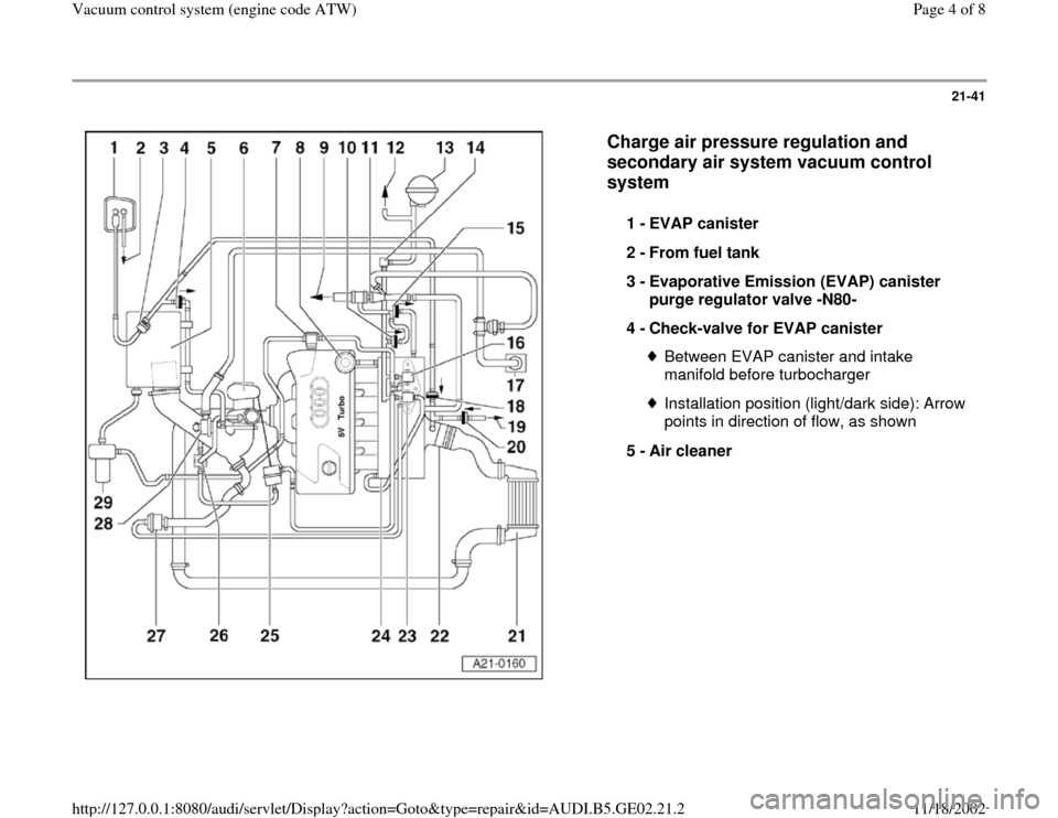
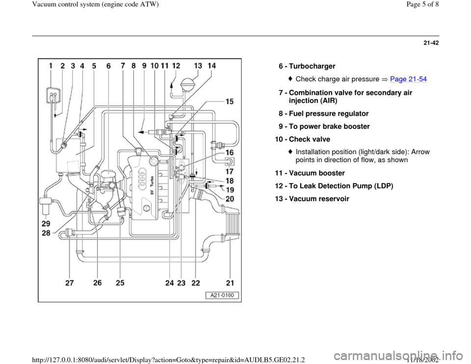
Charge air pressure regulation and
secondary air system vacuum control
system
1 -
EVAP canister
2 -
From fuel tank
3 -
Evaporative Emission (EVAP) canister
purge regulator valve -N80-
4 -
Check-valve for EVAP canister Between EVAP canister and intake
manifold before turbocharger Installation position (light/dark side): Arrow
points in direction of flow, as shown
5 -
Air cleaner
Pa
ge 4 of 8 Vacuum control s
ystem
(en
gine code ATW
)
11/18/2002 htt
p://127.0.0.1:8080/audi/servlet/Dis
play?action=Goto&t
yp
e=re
pair&id=AUDI.B5.GE02.21.2
Page 5 of 8
21-42
6 -
Turbocharger
Check charge air pressure Page 21
-54
7 -
Combination valve for secondary air
injection (AIR)
8 -
Fuel pressure regulator
9 -
To power brake booster
10 -
Check valve
Installation position (light/dark side): Arrow
points in direction of flow, as shown
11 -
Vacuum booster
12 -
To Leak Detection Pump (LDP)
13 -
Vacuum reservoir
Pa
ge 5 of 8 Vacuum control s
ystem
(en
gine code ATW
)
11/18/2002 htt
p://127.0.0.1:8080/audi/servlet/Dis
play?action=Goto&t
yp
e=re
pair&id=AUDI.B5.GE02.21.2
Page 6 of 8
21-43
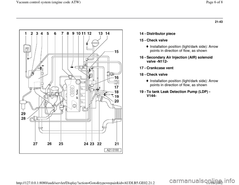
14 -
Distributor piece
15 -
Check valve
Installation position (light/dark side): Arrow
points in direction of flow, as shown
16 -
Secondary Air Injection (AIR) solenoid
valve -N112-
17 -
Crankcase vent
18 -
Check valve Installation position (light/dark side): Arrow
points in direction of flow, as shown
19 -
To tank Leak Detection Pump (LDP) -
V144-
Pa
ge 6 of 8 Vacuum control s
ystem
(en
gine code ATW
)
11/18/2002 htt
p://127.0.0.1:8080/audi/servlet/Dis
play?action=Goto&t
yp
e=re
pair&id=AUDI.B5.GE02.21.2
Page 7 of 8
21-44
20 -
Check valve
Installation position (light/dark side): Arrow
points in direction of flow, as shown
21 -
Charge air cooler With charge air pressure sensor -G31-
22 -
Throttle valve control module -J338-
23 -
Recirculating valve for turbocharger -
N249- Checking Page 21
-48
24 -
Intake manifold
With Intake Air Temperature (IAT) sensor -
G42-
Pa
ge 7 of 8 Vacuum control s
ystem
(en
gine code ATW
)
11/18/2002 htt
p://127.0.0.1:8080/audi/servlet/Dis
play?action=Goto&t
yp
e=re
pair&id=AUDI.B5.GE02.21.2
Page 8 of 8
21-45
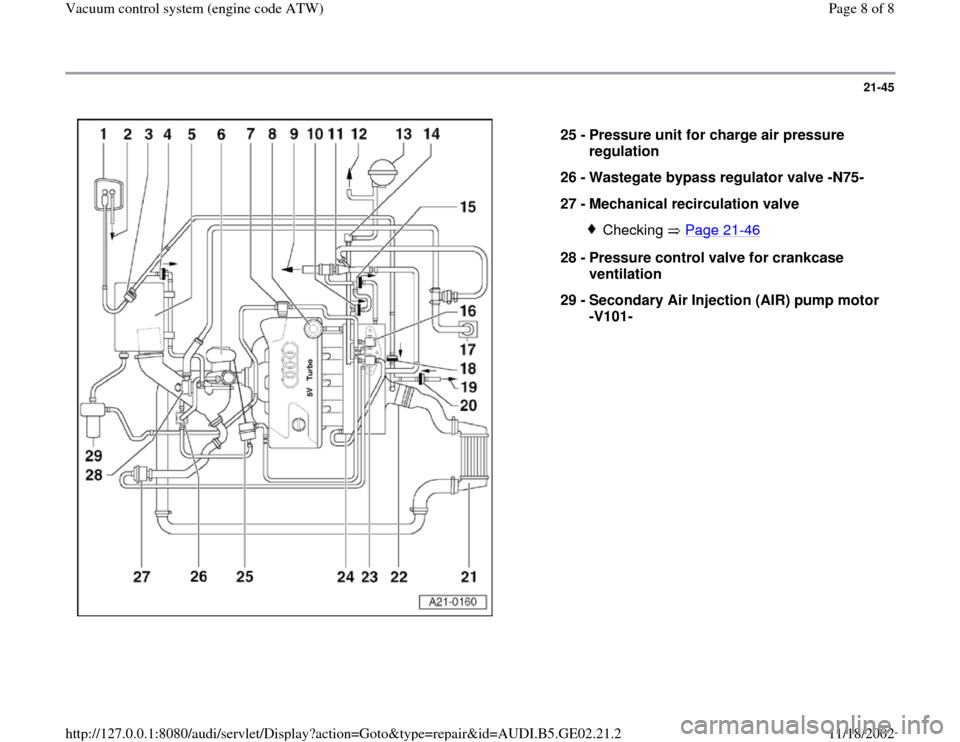
25 -
Pressure unit for charge air pressure
regulation
26 -
Wastegate bypass regulator valve -N75-
27 -
Mechanical recirculation valve
Checking Page 21
-46
28 -
Pressure control valve for crankcase
ventilation
29 -
Secondary Air Injection (AIR) pump motor
-V101-
Pa
ge 8 of 8 Vacuum control s
ystem
(en
gine code ATW
)
11/18/2002 htt
p://127.0.0.1:8080/audi/servlet/Dis
play?action=Goto&t
yp
e=re
pair&id=AUDI.B5.GE02.21.2
Trending: light, fuel, warning, ABS, check engine, brake light, sensor
