technical data AUDI TT 2021 Owner´s Manual
[x] Cancel search | Manufacturer: AUDI, Model Year: 2021, Model line: TT, Model: AUDI TT 2021Pages: 280, PDF Size: 99.18 MB
Page 6 of 280
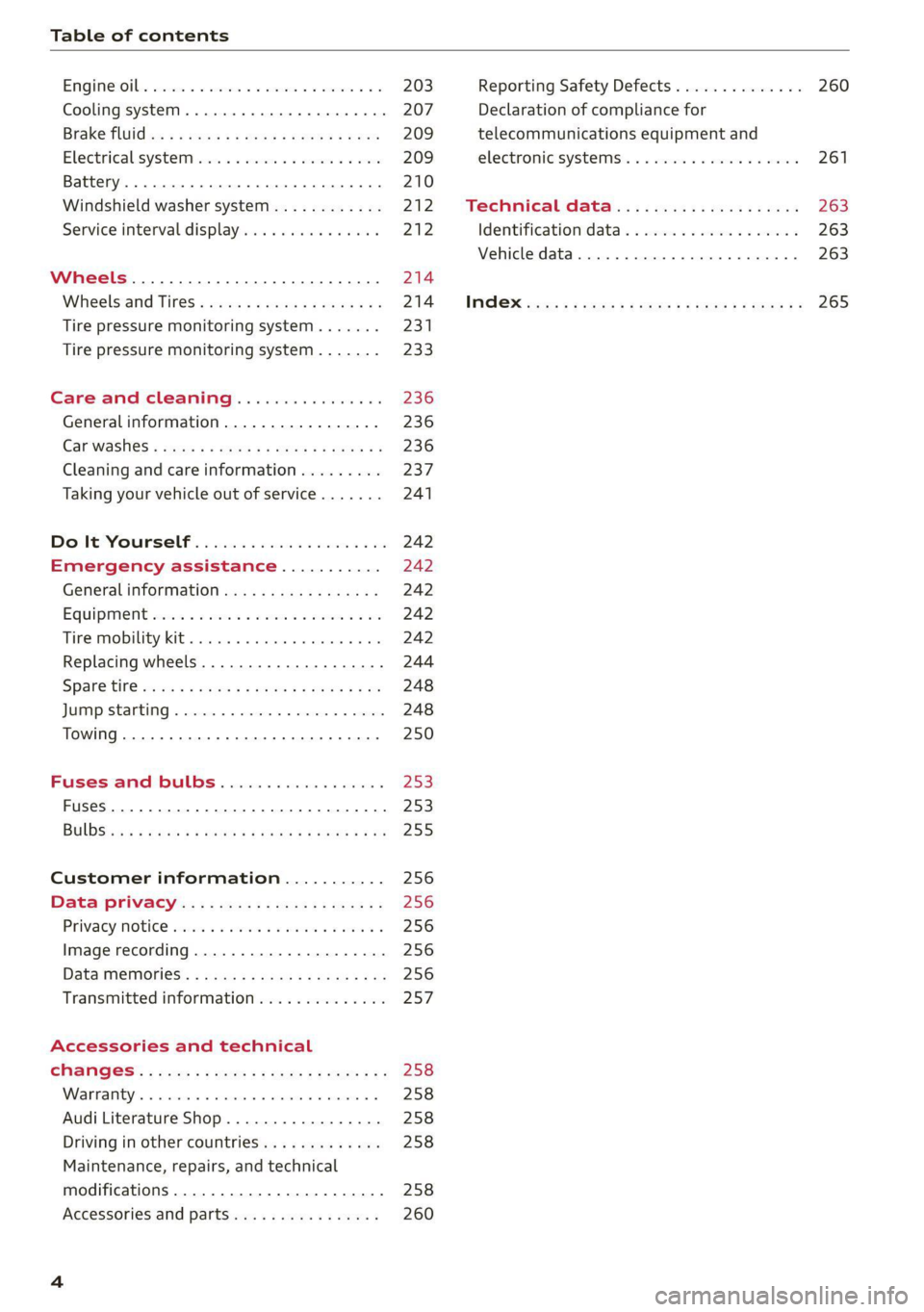
Table of contents
ENQine:Otbss cscceoe sv sereue ov emacs av creme 2 ae
Cooling systeM............. 0c eee eee
Brake fluid wu + « meay 2 x eeu 2 eapsea 2 oR
Electrical.system ws s 2 cswn ee eee ee oe
Battery. ...... 00... ese eee ec eee
Windshield washer system...........-
Service interval display...............
Tire pressure monitoring system.......
Tire pressure monitoring system.......
Care and cleaning................
Generalinformation.................
Car washes « scys + © suas ¢ © gees ¢ ¥ ees ee
Cleaning and care information.........
Taking your vehicle out of service.......
Do lt Yourself ; « ie: 5 eis es viens 6 oe
Emergency assistance...........
Generalinformation.................
EQUIPMENE scsi 3 5 serooe & ween ww aio wo
Tire mobility kit... 6.0.0... cee eee eee
Replacing wheels..............--.04.
SParetire ccies « » caus xs sass & & Hares oo
Customer information...........
Data: Privacy «: : . see. ss sees sv eens
Privaty Obie’ ssisins sn seman on nase 3 seo 5
Image recording.................0008
Date MEMGRESS < mss s x waves s & eiem » ERS
Transmitted information..............
Accessories and technical
Warrants « mesos © nrozwne © nreasoe ¥ 6 ater a
Audi Literature Shop.................
Driving in other countries.............
Maintenance, repairs, and technical
modifications ...................000.
Accessories and parts................
Reporting Safety Defects.............. 260
Declaration of compliance for
telecommunications equipment and
electronic systems .............-00005 261
Technical data................0005 263
Identification data................... 263
Vehicle data............ 0.0.00 0 0000 263
MGR cows « + cows 5 2 cee 5 ¢ ewes 5 6 ewe 9 265
Page 14 of 280
Instrument cluster
At temperatures below 41 °F (+5 °C), a snowflake
symbol appears in front of the temperature dis-
play > A.
ZA WARNING
Do not assume the roads are free of ice based
on the outside temperature display. Be aware
that there may be ice on roads even when the
outside temperature is around 41 °F (+5 °C)
and that ice can increase the risk of accidents.
Fuel level
The display @ > page 10, fig. 3 only works when
the ignition is switched on. When the display has
reached the reserve mark, a red LED turns on and
the iy indicator light turns on > page 198.
For the tank capacity in your vehicle, refer to the
Technical Data > page 264.
@) Note
Never drive until the tank is completely emp-
ty. The irregular supply of fuel that results
from that can cause engine misfires. Uncom-
busted fuel will then enter the exhaust sys-
tem. This can cause overheating and damage
to the catalytic converter.
Multifunction steering
wheel
87.6 MHz
cS BAL
90.0 MHz
90.5 MHz
91.5 MHz
TRON Lard
Fig. 5 Driver information system display
12
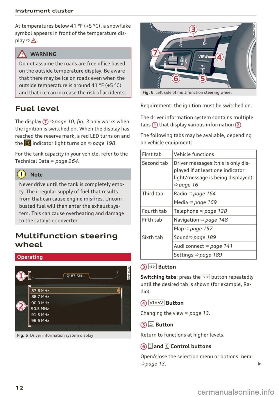
Fig. 6 Left side of multifunction steering wheel
Requirement: the ignition must be switched on.
The driver information system contains multiple
tabs (—) that display various information @).
The following tabs may be available, depending
on vehicle equipment:
First tab Vehicle functions
Second tab | Driver messages (this is only dis-
played if at least one indicator
light/message is being displayed)
=>page 16
Third tab Radio > page 164
Media > page 169
Fourth tab | Telephone > page 128
Fifth tab Navigation > page 148
Map > page 157
Sixth tab Sound> page 189
Audi connect > page 141
Settings > page 189
@|s=] Button
Switching tabs: press the [<>] button repeatedly
until the desired tab is shown (for example, Ra-
dio).
@ MEW] Button
Changing the view > page 13.
© [=] Button
Return to functions at higher levels.
© and [| Control buttons
Open/close the selection menu or options menu
=> page 13.
Page 200 of 280
Checking and Filling
continue fueling, or else the expansion space in
the tank will be filled with fuel.
> After the fuel pump has switched off, wait five
seconds before removing the nozzle to allow
the rest of the fuel to finish dripping into the
fuel tank.
> Close the fuel filler door and then press on the
left side until it latches.
The correct fuel type for your vehicle can be
found ona label located on the inside of the fuel
filler door. For additional information on fuel, see
=> page 196.
For the tank capacity in your vehicle, refer to the
Technical Data > page 264.
Messages
If the Ay indicator light appears with a corre-
sponding message, refuel the vehicle.
1D] Tank system: malfunction! Please contact
Service
There is a malfunction in the fuel tank system.
Drive to an authorized Audi dealer or authorized
Audi Service Facility immediately to have the
malfunction corrected.
flying sparks. Sparks can start a fire when
refueling.
Z\ WARNING
Improper fueling procedures and improper
handling of fuel can lead to explosions, fires,
severe burns, and other injuries.
— Do not smoke. Keep away from open flames.
— The ignition must be switched off when re-
fueling.
— Mobile devices, radio devices, and other ra-
dio equipment should always be switched
off when refueling. Electromagnetic rays
could cause sparks and start a fire.
— If you do not insert the fuel pump nozzle all
the way into the filler tube, then fuel can
leak out. Spilled fuel can ignite and start a
fire.
— Never get into the vehicle when refueling. If
there is an exceptional situation where you
must enter the vehicle, close the door and
touch a metal surface before touching the
fuel pump nozzle again. This will reduce the
risk of electrostatic discharge that can cause
ZA\ WARNING
Audi does not recommend transporting fuel
containers inside the vehicle. Fuel could leak
out of the container and ignite, especially dur-
ing an accident. This can cause explosions,
fires, and injuries.
— If you must transport fuel in a fuel contain-
er, note the following:
— Always place the fuel container on the
ground before filling. Never fill the fuel
container with fuel while it is inside or on
the vehicle. Electrostatic discharge can oc-
cur while refueling and the fuel vapors
could ignite.
— When using fuel containers made of met-
al, the fuel pump nozzle must always re-
main in contact with the container to re-
duce the risk of static charge.
— Insert the fuel pump nozzle as far as possi-
ble into the filler opening while refueling.
— Follow the applicable legal regulations in
the country where you are driving when
using, storing and transporting fuel con-
tainers.
— Make sure that the fuel container meets
the industry standards, for example ANSI
or ASTM F852-86.
198
@) Note
— Remove fuel that has overflowed onto any
vehicle components immediately to reduce
the risk of damage to the vehicle.
— Never drive until the fuel tank is completely
empty. The irregular supply of fuel that re-
sults from that can cause engine misfires.
Uncombusted fuel may enter the exhaust
system and increase the risk of damage to
the catalytic converter.
@) For the sake of the environment
— Do not overfill the fuel tank, or fuel could
leak out when the vehicle is warming up.
— Fuel should never enter the sewer system or
come into contact with the ground.
Page 258 of 280
![AUDI TT 2021 Owner´s Manual Data privacy
Data privacy
Privacy notice
You can find information about responsibility for
data protection in the MMI.
Applies to: MMI: Select: [MENU] button > Audi
connect > right AUDI TT 2021 Owner´s Manual Data privacy
Data privacy
Privacy notice
You can find information about responsibility for
data protection in the MMI.
Applies to: MMI: Select: [MENU] button > Audi
connect > right](/img/6/40287/w960_40287-257.png)
Data privacy
Data privacy
Privacy notice
You can find information about responsibility for
data protection in the MMI.
Applies to: MMI: Select: [MENU] button > Audi
connect > right control button > About Audi con-
nect.
Image recording
Surrounding area monitoring
Applies to: vehicles with surrounding area monitoring
Some vehicle functions require the vehicle’s path
to be detected and evaluated. This is done by
cameras installed permanently on the vehicle
that detect objects in the vehicle's surroundings
(such as obstacles or guard rails). The live images
from the cameras are transmitted to the applica-
ble control module.
The camera images are transmitted to the appli-
cable control module and stored for processing.
The control module analyzes the current camera
image using image evaluation software. This im-
age evaluation software detects anonymized
technical measurements, such as distances to ob-
jects. The control module evaluates these techni-
cal measurements and makes it possible for the
assist systems to control the vehicle, if necessary.
Data memories
~ 1p o
S| =z
x a.
Fig. 200 Driver's side footwell: connection port for the On
Board Diagnostic System (OBD)
Your vehicle is equipped with electronic control
modules for various vehicle systems such as the
256
airbags. These vehicle control modules store data
while driving normally that is required by an au-
thorized Audi dealer or authorized Audi Service
Facility for diagnosis and repair purposes. Only
certain types of data are recorded for a very short
period of time if a control module has detected a
system event. No noises, conversations, or im-
ages will be recorded in the vehicle.
The data may include information such as the ve-
hicle speed, the direction of travel, and informa-
tion about the brake system, or also the behavior
of the restraint system in the event of an acci-
dent. The stored data can be exported and down-
loaded with special devices, which must be con-
nected directly to the vehicle.
On Board Diagnostic System (OBD)
There is a diagnostic connector socket in the driv-
er's side footwell to read out the various control
modules and the event data recorder. Data re-
garding the function and condition of the elec-
tronic control modules is stored in the event
memory. Only have an authorized Audi dealer or
authorized Audi Service Facility read out and de-
lete the event memory.
ZA\ WARNING
— Incorrect use of the connection port for the
On Board Diagnostic System can cause mal-
functions, which can then result in accidents
and serious injuries.
— Only allow an authorized Audi dealer or au-
thorized Audi Service Facility to read out the
motor data.
rash data recorder
Crash data recorder/event data recorder
Your vehicle is not equipped with a crash data re-
corder.
Vehicle information is stored temporarily in a
crash data recorder. This provides detailed in-
sight into the circumstances of an accident. In
vehicles with an airbag system, accident-related
information such as impact speed, seat belt sta-
tus, seat positions and deployment times may be >
Page 261 of 280

8S1012721BE
Accessories and technical changes
Usually maintenance and repair work requires
special tools, measuring devices, and other
equipment that is available to trained vehicle
technicians in order to help ensure that your vehi-
cle and all of its systems operate correctly, relia-
bly, and safely. Performing work on the vehicle
incorrectly can impair the operation and reliabili-
ty of your vehicle and may void one or more of
your vehicle's warranties.
Technical Modifications
Interference with electronic components, their
software, the wiring, and data transfer may cause
malfunctions. Because of the way electronic com-
ponents are interconnected, such malfunctions
can also impair systems that are not directly in-
volved. This means that you risk both a substan-
tial reduction in the operational safety of your ve-
hicle and increased wear of vehicle components.
Some convenience functions, such as the conven-
ience turn signal function, individual door open-
ing function, and displays, can be reprogrammed
using special workshop equipment. If functions
are reprogrammed, the information and descrip-
tions about these functions in this Owner's Man-
ual may no longer apply to the changed func-
tions. Audi recommends that an authorized Audi
dealer or authorized Audi Service Facility perform
and verify any reprogramming procedures.
— Never perform any work in the motor com-
partment unless you know exactly how to
carry out the job and have the correct tech-
nical information and the correct tools.
— If you are uncertain about what to do, have
the work performed by an authorized Audi
dealer, an authorized Audi Service Facility,
or another qualified workshop. Serious per-
sonal injury may result from improperly per-
formed work.
Z\ WARNING
Maintenance work, repairs, or technical modi-
fications to the vehicle (such as installing ad-
ditional equipment) that is not performed
correctly can cause serious injuries and in-
crease the risk of an accident.
ZA\ WARNING
The motor compartment in any motor vehicle
is a potentially dangerous area and can cause
serious personal injury.
— Always use extreme caution when doing any
work in the motor compartment. Always fol-
low commonly accepted safety practices and
use common sense. Never risk personal in-
jury.
@) Note
— Maintenance work, repairs, or technical
modifications to the vehicle (such as instal-
ling additional equipment) that is not per-
formed correctly can cause vehicle damage.
— If emergency repairs must be performed,
take your vehicle to an authorized Audi deal-
er or authorized Audi Service Facility as soon
as possible.
— Audi is not liable for damage to the vehicle
resulting from failure to comply with these
guidelines.
@) For the sake of the environment
— Regular maintenance can help protect the
environment.
— Technical modifications to the vehicle can
have a negative impact on fuel consumption
and vehicle emissions.
@) For the sake of the environment
Certain components in your vehicle such as
undeployed airbag modules, pretensioners
and remote control batteries may contain Per-
chlorate Material - special handling may ap-
ply, See www.dtsc.ca.gov/hazardouswaste/
perchlorate. When the vehicle or parts of the
restraint system including airbag modules
and safety belts with pretensioners are scrap-
ped, all applicable laws and regulations must
be observed. Your authorized Audi dealer is
familiar with these requirements and we rec-
ommend that you have your dealer perform
this service for you.
259
Page 265 of 280
8S1012721BE
Technical data
Technical data
Identification data
Vehicle data label
XXX X= HKNK WOK XX
(Hae wrccnce XX XNKKKNKK
Frm XXX XX
2
3 }—— MOTORS / GET. 8
eco au cone XXX
LACKNR / INNENAUSS.
PANT NO, INTEROR XXXX [XXX XXX / XX
M. - AUSST. / OPTIONS
EOA 7D5 4UB 6XM 5SG
2EH
JOZ 1LB 1AS
3FC SMU 7X1
FOA 9G3 0G7 OYH OJF
TL6 3KA 8EH U1A X9B QZ7
1XW 8Q3 9Q8 8Z4 D2D
716 CV7 7KO 4X3 2K2
3L4 4KC 3Y0 413
1SA 7GB Q1A
RAZ-0668
XX XXXXXXX XX. X.X XX
XXX KW XXX
XXX XXX
SRW
1BA
SH
5D2
4GQ
ee
Fig. 201 Vehicle identification label
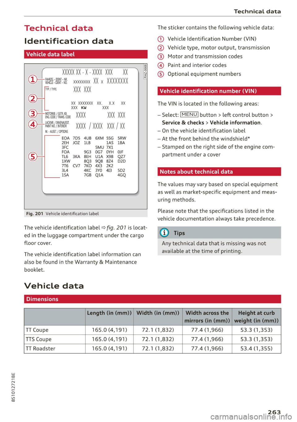
The vehicle identification label > fig. 207 is locat-
ed in the luggage compartment under the cargo
floor cover.
The vehicle identification label information can
also be found in the Warranty & Maintenance
booklet.
Vehicle data
The sticker contains the following vehicle data:
@ Vehicle Identification Number (VIN)
@ Vehicle type, motor output, transmission
® Motor and transmission codes
@) Paint and interior codes
© Optional equipment numbers
Vehicle identification number (VIN)
The VIN is located in the following areas:
MENU — Select: button > left control button >
Service & checks > Vehicle information.
— On the vehicle identification label
— At the front behind the windshield*
— Stamped on the right side of the engine com-
partment under a cover
Notes about technical data
The values may vary based on special equipment
as well as market-specific equipment and meas-
uring methods.
Please note that the specifications listed in the
vehicle documentation always take precedence.
G) Tips
Any technical data that is missing was not
available at the time of printing.
Length (in (mm)) | Width (in (mm)) | Width across the | Height at curb
mirrors (in (mm)) | weight (in (mm))
TT Coupe 165.0 (4,191) 72.1 (1,832) 77.4 (1,966) 53.3 (1,353)
TTS Coupe 165.0 (4,191) 72.1 (1,832) 77.4 (1,966) 53.3 (1,353)
TT Roadster 165.0 (4,191) 72.1 (1,832) 77.4 (1,966) 53.4 (1,355)
263
Page 266 of 280
Technical data
(er) Feb a(t)
Fuel tank 14.5 gal (55 L)
Windshield and headlight washer system* 4.0 qt (3.8L)
A/C system refrigerant oil
The exact type and amount of refrigerant oil in
the A/C system is specified on the sticker on the
refrigerant compressor.
Refrigerant oil 110g +/-10g
[=
|
[\<
FVM ANU
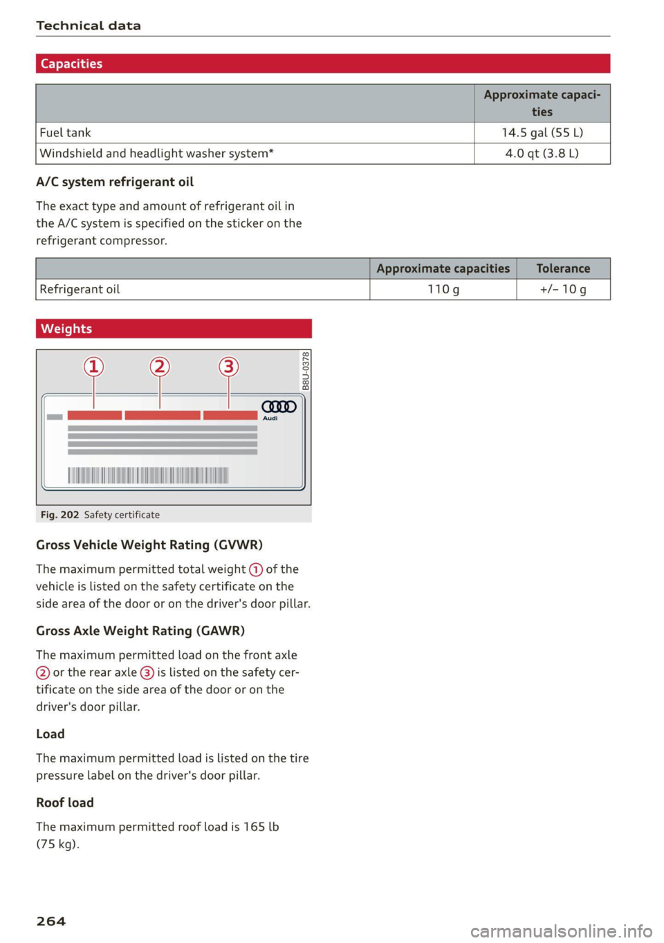
Fig. 202 Safety certificate
Gross Vehicle Weight Rating (GVWR)
The maximum permitted total weight ( of the
vehicle is listed on the safety certificate on the
side area of the door or on the driver's door pillar.
Gross Axle Weight Rating (GAWR)
The maximum permitted load on the front axle
@ or the rear axle @) is listed on the safety cer-
tificate on the side area of the door or on the
driver's door pillar.
Load
The maximum permitted load is listed on the tire
pressure label on the driver's door pillar.
Roof load
The maximum permitted roof load is 165 lb
(75 kg).
264
Page 276 of 280
Index
Settings
Directory... ... cece eee eee eee eee 139
Mapaeos x 2 aeee x & seem o 2 eH oe ee 2 Eee 159
Medias. «= seman ss wave ox amanus ¥ ancaaneos « saners 180
Navigation...........0..0..0200 eee ee 155
RadiGuess: x x game x = seme os wee fs eee a oe 167
System (MM]) « « asiws + wom 6 wan we mewn 189
Telephone........... 00 eee eee eee 139
Voice recognition system.............. 190
Wi-Fi hotspot coicvs <5 esorn es ows oe ween oe 146
Setting the language.................0. 189
Shift light indicator’: sess ss vows se wae sy we 15
Shift paddles (automatic transmission) .... . 85
Shuffle... 2... eee eee eee 180
Side assist... 2... eee eee eee 93
Adjusting the brightness................ 95
Cleaning the sensors...........0000005 237
Sensor range... ..- 22... cece ee eee 94
Switching on and off...............0-0- 95
also refer to Side assist... .......0000006 93
SIM card Teader’s « « wera 2 » enw 2 2 ges 2 ges 142
Ski DaGiics + ais & © nets & ¥ MOE oo SOUS FE 66
Smartphone
referto Telephone...............00005 128
Snowboard bag ; ¢ «sess ¢ seas cones a ewes 66
SNOW. Chains: « = scan & o wee eee & Hae & 229
Socket
refer to Power sourceS..........--.200-5 63
Software update
refer to System update (MMI).......... 192
Software (MMI)
Licensing agreements................. 194
Updates 2 aces ¢ seu & y reen ¢ come x oes 192
MersiOMies ¢ 2 ccmers @ v serses © v sone 2 6 seme 2 Y 192
SParetiress « s mse se seas x e wows x e ees «es 248
Speed dependent volume control......... 193
Speedometer’: sexs sz ween sy ses x eee gee 10
Speed warning system.............2--00. 89
Speller... 20... 2. eee eee eee eee ee 117
Sport displays....... 0.0.0... cee eee eee ee 15
Sport mode...... 2... eee eee eee eee ee 105
SPOT MWh & viene «+ srenoire w e embewie a w ease a wa 13
Sporty CrivVing wien «+ wows = 0 wow © © eee oo ws 81
Stabilization program
refer to Electronic Stabilization
Control (ESC)... 2... eee 104
274
Start/Stop SYSte Mier «2 ssa = 2 ance ev eae 77
Engine does not switch off.............. 78
Engine starts automatically............. 78
Indicator lights: . . cise oe cme «sane ee oe 77.
MessageS.... 0.2... cece eee ee eee eee 79
Stopping and starting the engine......... 77
Switching off and/oni. « «swe sa wei «2 ames 79
START ENGINE STOP button........... 75,76
SUAEIMG EO ArIVEle: = = coun + x coups oe Rue ye om 80
Starting (Cngine)ixe « «wees x » ween ss mee 2 oe 75
Steering............ 00.0. cece eee eee 107
Indicator lighticcs ss scape seems so ewes ve 16
also refer to Steering...............4. 107
Steering
wheel
Adjusting ...... 0.6... cece eee eee 48
Shift paddles (automatic transmission) .... 85
also refer to Multifunction
steering wheel..............-.0000- 12,14
Steps for determining correct load limit... 228
Stopover (navigation) .............0000- 153
Storage:areasiia: « 6 wns e+ were « ¥ ewes © 9 swear 64
Streaming
refer to Online media................. 174
S tronic (automatic transmission).......... 81
Subtithes(DVD) « + seovse x 6 swine a 6 seaians 6 @ ones 180
SUIWISOFS.« wesu = 5 wane 6 s wang x % geRE & & BEER 41
SUSPENSION CONtOlws « < nem: « pea se ews 96
Swappinigiealls): « « seme 2s amex zs mee s oe 133
Switching daytime running lights on and off. 38
Switching the ignitionon................- 75
Symbols... 0.00... 0 cece eee eee eee 119
NaViGBtiOnece = y sews ¢ 2 deaik 2 eee § Bas 157
TRAFIC scoxe os esata oe ore 6 2 aor ae aeRO 161
also refer to Indicator lights.............. 7
System settings (MMI) w.cesx « cncu ee wane a « 189
System update (MMI)...............0088 192
System VOLUME « ace s case es nae ev eee os 193
T
Tachometer iiss « + wus ¢ ¢ were a eeoee 4 2 10,11
Technical datas: «sews < pase se nee ss ve 263
Technical modifications................. 258
Telephone.......... 0. cece cece eee eee 128
Audi phone box... .:c..sseecesneeees 130
Connecting a mobile phone............ 128
Dialinganumber..............-.0000- 132