instrument cluster AUDI TT ROADSTER 2008 Owners Manual
[x] Cancel search | Manufacturer: AUDI, Model Year: 2008, Model line: TT ROADSTER, Model: AUDI TT ROADSTER 2008Pages: 316, PDF Size: 70.1 MB
Page 14 of 316
Inst rum ent s a nd warning /indi cato r li ghts
Instruments and warning/indicator lights
Instruments
Instrument cluster and controls
The instrument cluster is your central source of informa
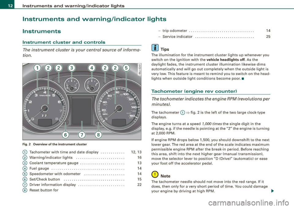
tion .
6
Fig . 2 Ove rv iew of the ins trum ent cluster
0
0
0
©
©
©
G)
©
Tachometer with time and date display ......•.....
Warning/indicator lights .. ... ..... ... ........ .. .
Coolant temperature gaug e .... ... ...... ...... .. .
Fuel gauge .. .... ... .. ...... .... ... ..... ... ... .
Speedome ter with odometer ..... .... ... .. .. ... .
Set/Chec k button ..... ... ..... ..... ... ........ .
Driver information display
Reset but ton for
~
"' N 9
i
12, 13
16
13
14
14
15
22
- trip odometer
- Service indicator
[ i ] Tip s
14
25
The illumination for the instrument cluster lights up whenever you
switch on the ign ition with the
ve hicle hea dlight s off. As the
daylight fades, the instrument cluster illumination likewise dims
automatically and wil l go out completely when the outside light is
very low. This feature is meant to remind you to switch on th e head
lights when outside light conditions become poor. •
Tachometer (engine rev counter)
The tachometer indicates the engine RPM (revolutions per
minutes) .
The tachometer 0 ~ fig. 2 is the left of the two large c lock -type
displays.
The engine turns at a speed
1,000 times the single digit in the
display, e.g . if th e ne edle is pointing a t the
"2" the engine is turning
at 2,000 RPM .
If engine RPM drops below 1,500, you should downshif t to the next
lower gear . The red ar ea at the end of th e scale indica tes maximum
permissible engine RPM after the break- in period. Before reaching
th is area , shift into the next higher gear (manua l transmission),
move the selec tor lever to position "D (Drive)" (automatic) or ease
your foot off the accelerator pedal.
0 Note
T he tachometer need le should not move into the red range . If it
does, then on ly for a very short period of time . You could damage
your engine by driving a t high RPM. ...
Page 15 of 316
<£> For the sake of the environment
Upshifting early saves fuel and reduces engine noise. •
Digital clock with date display
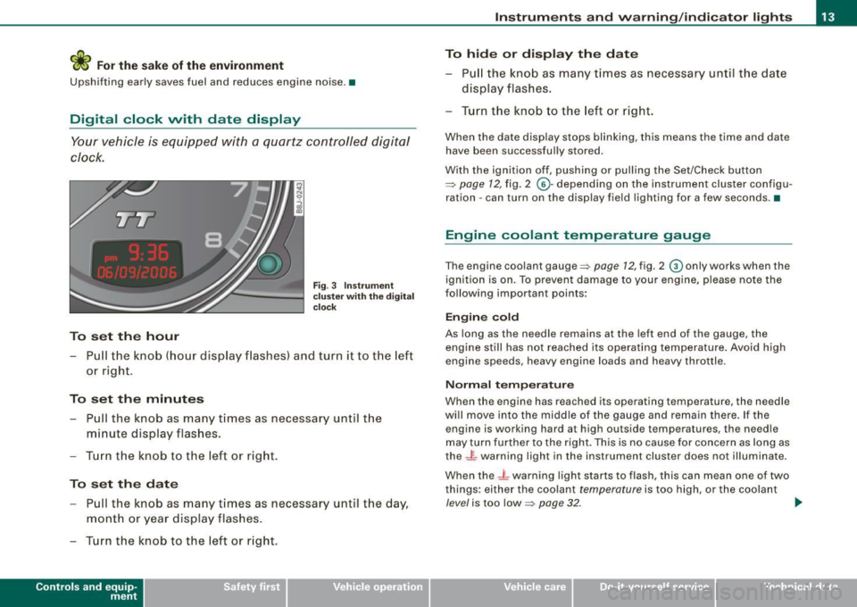
Your vehicle is equipped with a quartz controlled digital
clock.
To set the hour
Fig. 3 Instrument
c luste r with the digital
c lock
- Pull the knob (hour display flashes) and turn it to the left
or right.
To set the minutes
- Pull the knob as many times as necessa ry until the
m in ute display flashes.
- Turn the knob to the left or right.
To set the date
-Pull the knob as many times as necessary until the day,
month or year display flashes.
- Turn the knob to the left or right.
Con tro ls and eq uip
ment
Instruments and warning /indicator lights
To hide or display the date
- Pull the knob as many times as necessary until the date
display flashes .
- Turn the knob to the left or right.
When the date display stops blinking, this means the time and date
have been successfully stored.
With the ignition off, pushing or pulling the Set/Check button
~ page 12, fig. 2 ©-depending on the instrument cluster configu
ration - can turn on the display field lighting for a few seconds .•
Engine coolant temperature gauge
The engine coolant gauge~ page 12, fig. 2 © only works when the
ignition is on. To preven t damage to your engine, please note the
following important points:
Engine cold
As long as the needle remains at the left end of the gauge, the
engine still has not reached its operating temperature . Avoid high
engine speeds, heavy engine loads and heavy throttle.
Normal temperature
When the engine has reached its operating temperature, the needle
will move into the middle of the gauge and remain there. If the
engine is working hard at high outside temperatures, the needle
may turn further to the right. This is no cause for concern as long as
the -~- warning light in the instrument cluster does not illuminate.
When the
_J _ warning light starts to flash, this can mean one of two
things: either the coolant
temperature is too high , or the coolant
level is too low~ page 32 . ~
Vehicle care I I irechnical data
Page 16 of 316
Instruments and warning/indicator lights
& WARNING
• Always observe the warning in=;, page 212, " Engine compart
ment" before opening the engine hood and checking the engine
coolant level.
• Never open the engine hood if you see or hear steam , or if you
see engine coolant dripping from the engine compartment . You
c ould burn your self. Let the engine cool off first so that you cannot
hear or see any steam or engine coolant .
0 Note
• Mounting additiona l lights or accessories in front of the a ir inlets
reduces the co oling effect of the radiat or. At high outside tempera
tures or h igh engi ne load, the eng ine could overheat.
• The fron t spoile r has been designed t o properly dis trib ute the
coo ling air when the veh icle is mov ing . If the spo iler is damaged,
this could red uce the coo ling effect and the engine co uld then ove r
heat. Ask your authorized Audi deale r for assistance. •
Fuel gauge
The fuel gauge wor ks only when the ignition is on .
When the needle reaches the red area, the warning light in the i nstrument cluster w ill illu m ina te =;,
page 35 . Thi s means yo u
have approx imate ly 1.9 gallons (7 litres) of fuel left in the tank.
Time
to refuel!
The tota l tank capacity of your vehicle is listed in=;, page 297. Be
awa re of the diffe rent ta nk capaci ties of front -wheel a nd q uat tro®
a ll- w hee l d ri ve models .
0 Note
Never run the tank comple tely dry! An irre gular suppl y of fuel can
cause engine m isf iring and fuel could enter into the exhaust system.
The catalytic converter could then overheat and be
damag ed. •
Speedometer with odometer
The speedometer shows y ou t he vehic le speed, and the
o dome ter sho ws you ho w ma ny m iles (kilo meters) yo u
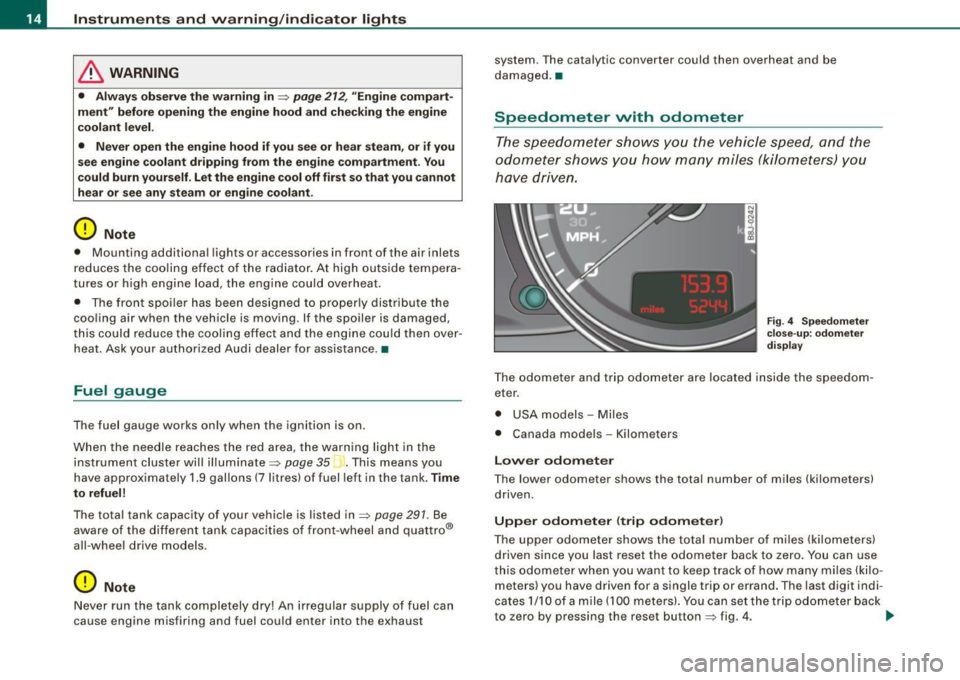
have dri ven.
Fig . 4 Speedomete r
close -up : odomet er
displ ay
T he od ometer an d trip odo mete r are locate d insid e th e spe edom
eter .
• USA model s - Miles
• Canada mode ls - Kilometers
Lower odometer
The lower odometer shows the total number of miles (kilometers)
d riven.
Upper odometer (trip odometer )
The upper o dometer shows the tota l number o f mi les ( kilom eters)
driven since you last reset the odometer bac k to ze ro . You can use
thi s odomete r w hen you want to keep track of how ma ny m iles ( kilo
meters) you have driven for a single trip or errand. The last digit indi
cates 1/10 of a m ile (10 0 meters). You ca n set t he trip od o meter back
to zero by pressing the reset button
=;, fig . 4 . ..,,
Page 17 of 316
With the ignition off, pushing of the Set/Check button~ page 12,
fig. 2 © can turn on the display field lighting for a few seconds .
Malfunction message
If there is a malfunction somewhere in the instrument cluster, dEF
will appear in the trip odometer and will stay on. Contact your
authorized Audi dealer to have the problem corrected.
Immobilizer
When the ignition is switched on, the data on the ignition key are
scanned automatically.
If an unauthorized key was used, SAFE is displayed continuously in
the odometer display field. The vehicle cannot be operated
~ page 49.
[ i ] Tips
• The digital c lock and the odometer are turned on for about 30
seconds when the driver's door is opened.
• When the ignition is turned off, the odometer reading and the
digital clock with date display can be switched on for about
30 seconds by pressing the Set/Check button~
page 12, fig. 2 @ . •
Set /Check button
Con tro ls and eq uip
ment
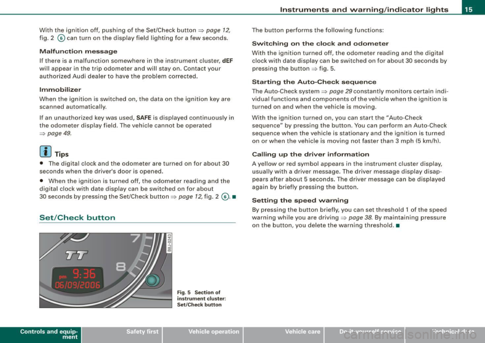
Fig . 5 Section of
in strument cluster:
Set/Check button
Instruments and warning /indicator lights
The button performs the following functions:
Switching on the clock and odometer
With the ignition turned off, the odometer reading and the digital
clock with date display can be switched on for about 30 seconds by
pressing the button~ fig. 5 .
Starting the Auto -Check sequence
The Auto -Check system ~ page 29 constantly monitors certain indi
v idual functions and components of the vehicle when the ignition is
turned on and when the vehicle is moving.
With the ignition turned on, you can start the "Auto -Check
sequence" by pressing the button. You can perform an Auto-Check
sequence when the vehicle is stationary and the ignition is turned
on or when the vehicle is moving not faster than 3 mph (5 km/h).
Calling up the driver information
A yellow or red symbol appears in the instrument cluster display,
usually with a driver message. The driver message display disap
pears after about 5 seconds. The driver message can be displayed
again by briefly pressing the button.
Setting the speed warning
By press ing the button brief ly, you can set threshold 1 of the speed
warning while you are driving~
page 38. By maintaining pressure
on the button, you delete the warning threshold.•
Vehicle care I I irechnical data
Page 21 of 316
Additional information about the electrically retractable rear spoiler
=:> page 187 . •
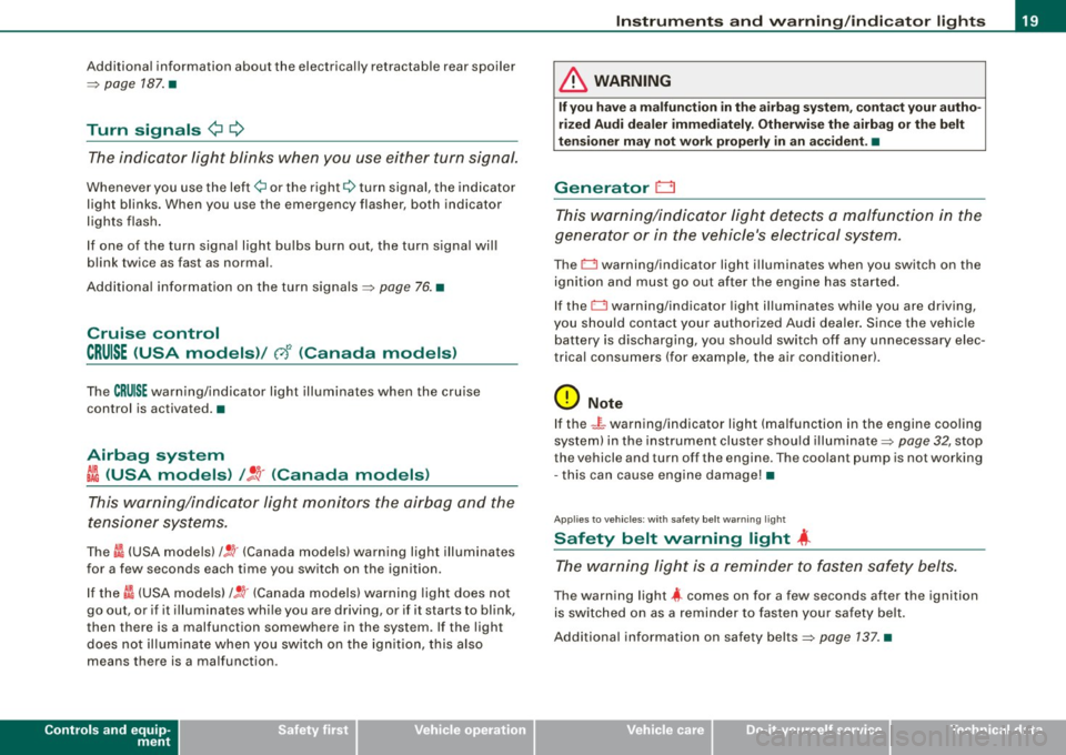
Turn signals ¢ Q
The indicator light blinks when you use either turn signal.
Whenever you use the left¢ or the right c::::> turn signal, the indicator
light blinks. When you use the emergency flasher, both indicator
lights flash .
If one of the turn signa l light bu lbs burn out, the turn signal will
blink twice as fast as normal.
Additiona l information on the turn signals :::::>
page 76. •
Cruise control
CRUISE (USA models )/ (')<> (Canada models)
The CRUISE warning/indicator light illuminates when the cruise
control is activated. •
Airbag system
~~ (USA models) / !_~· (Canada models)
This warning/indicator light monitors the airbag and the
tensioner systems .
The ti (USA models) !! 'tr (Canada models) warning light illuminates
for a few seconds each time you switch on the ignition .
If the m (USA mode ls)
/ J q· (Canada models) warning light does not
go out, or if it i lluminates whi le you are driving, or if it starts to blink,
then there is a malfunction somewhere in the system. If the light
does not illuminate when you switch on the ignition, this also
means there is a malfunction.
Controls and equip
ment
Instruments and warning /indi cator lights
& WARNING
If you have a malfunction in the airbag system, contact your autho
rized Audi dealer immediately. Otherwise the airbag or the belt
tensioner may not work properly in an accident. •
Generator 0
This warning/indicator light detects a malfunction in the
generator or in the vehicle's electrical system.
The D warning/indicator light illuminates when you switch on the
ignition and must go out after the engine has started.
If the D warning/indicator light illuminates while you are driving,
you should contact your authorized Audi deale r. Since the vehicle
battery is discharging, you should switch off any unnecessary elec
trical consumers (for example, the air conditioner).
0 Note
If the -~- warning/indicator light (malfunction in the engine cooling
system) in the instrument cluster shou ld illuminate :::::>
page 32, stop
the vehicle and turn off the engine . The coolant pump is not working
- this can cause engine damage!•
Applies to veh ic les : w ith safety belt warning l ight
Safety belt warning light 4
The warning light is a reminder to fasten safety belts.
The warning light 4 comes on for a few seconds after the ignition
is switched on as a reminder to fasten your safety belt.
Additional information on safety belts:::::>
page 137. •
I • •
Page 24 of 316
Driver inf ormation sy ste m
Driver information system
Introduction
General notes
The driver information display inside the instrument
cluster provides you, the driver, with important informa
tion.
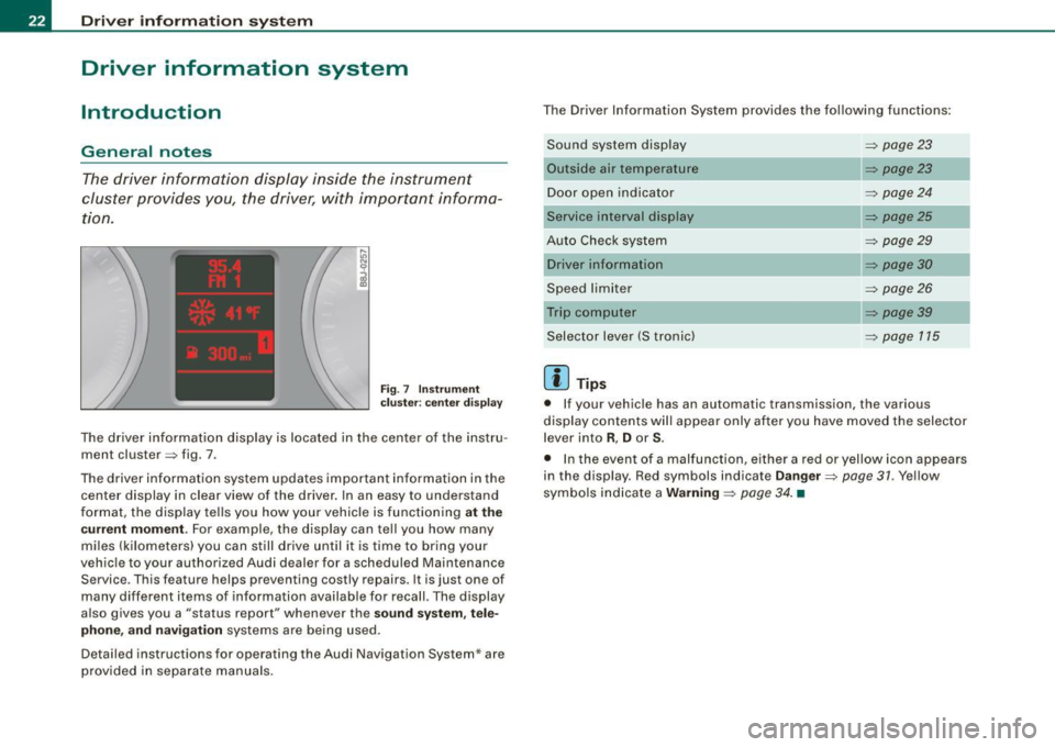
F ig. 7 In st rum ent
c luster : center d is p lay
The driver information display is located in the center of the instru
ment cluster => fig . 7 .
The driver information system updates important information in the center display in clear view of the driver. In an easy to understand
format, the display tells you how your vehicle is functioning
at t he
cu rre nt m omen t.
For example, the display can tell you how many
miles (kilometers) you can still drive until it is time to bring your
vehicle to your authorized Audi dealer for a scheduled Maintenance Service . This feature helps preventing costly repairs. It is just one of
many different items of information availab le for recall. The display
a lso gives you a "status report" whenever the
so und s ystem , tel e
ph on e, a nd navi gation
systems are being used.
Detailed instructions for operating the Audi Navigation System* are provided in separate manuals . The Driver Information System provides the following functions:
Sound system display
Outside air temperature
Door open indicator
Service interval display
Auto Check system
Speed limiter
Selector lever (S t ronic)
[ i ] Tip s
=> page 23
=> page23
=> page 24
=> page25
=> page29
=> page30
=> page 26
=> page 39
=> page 115
• If your vehicle has an automatic transmission, the various
display contents will appear only after you have moved the selector
lever into
R , D or S.
• In the event of a malfunction, e ither a red or yellow icon appears
in the display. Red symbols indicate
D anger => page 31 . Yellow
sy mbols indicate a
W arning => page 34 . •
Page 27 of 316
If, however, the Malfunction Indicator Lamp (MIU comes on,
always drive to your nearest authorized Audi dealer or qualified
workshop and have the vehicle checked.
For more information =>
page 216, "Refuelling".•
Service interval display
The service interval display reminds you when your next
service is due.
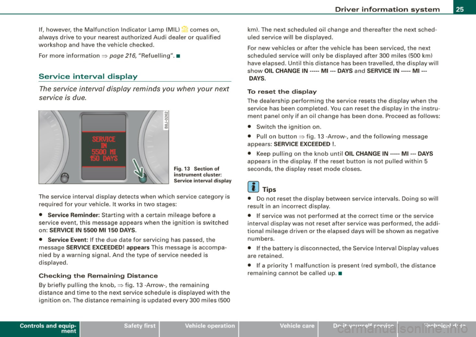
Fig. 13 Section of
instrument cluster:
Service interval display
The service interval display detects when which service category is
required for your vehicle. It works in two stages:
• Service Reminder : Starting with a certain mileage before a
service event, this message appears when the ignition is switched
on:
SERVICE IN 5500 Ml 150 DAYS.
• Service Event:
If the due date for servicing has passed, the
message
SERVICE EXCEEDED! appears This message is accompa
nied by a warning signal. And the type of service needed is
displayed.
Checking the Remaining Distance
By briefly pulling the knob,=> fig. 13 -Arrow -, the remaining
distance and time to the next service schedule is displayed with the
ignition on . The distance remaining is updated every 300 miles (500
Controls and equip
ment
Driver information system
km). The next scheduled oil change and thereafter the next sched
uled service will be displayed.
For new vehicles or after the vehicle has been serviced, the next
scheduled service will only be displayed after 300 miles (500 km)
have elapsed. Until this distance has been travelled, the display will
show
OIL CHANGE IN----- Ml ---DAYS and SERVICE IN----- Ml --
DAYS.
To reset the display
The dealership performing the service resets the display when the service has been completed . You can reset the display in the instru
ment panel only if an oil change has been done. Proceed as follows:
• Switch the ignition on .
• Pull on button=> fig.
13 -Arrow-, and the following message
appears:
SERVICE EXCEEDED !.
• Keep pulling on the knob until OIL CHANGE IN ---- -Ml ---DAYS
appears in the display. If the reset button is not pulled within 5
seconds, the display reset mode closes.
[ i] Tips
• Do not reset the display between service intervals. Doing so will
result in an incorrect display.
• If service was not performed at the correct time or the service
interval display was not reset after service was performed, the addi
tional mileage driven or the elapsed days will be shown as negative
numbers.
• If the battery is disconnected, the Service Interval Display values
are retained.
• If a priority 1 malfunction is present (red symbol), the distance
remaining cannot be called up. •
I • •
Page 28 of 316
Driver inf ormation sy ste m
On-Board Diagnostic system (08D)
Malfunction Indicator Lamp (MIL )
The Malfunction Indicator Lamp (MIU in the instrument cluster
=:> page 16, fig. 6 is part of the On -Board Diagnos tic (OBD II) system.
The warning/indicator ligh t ill uminates when the ignition is
switched on and goes out after the engine starts and the idle has
stabilized . This indicates that the MIL is working properly .
If th e light d oes not go out after the engine is started, or illuminates
while you are driving, a ma lfunction may exist in the engine system.
If the light starts flashing, the catalytic converter cou ld be damaged .
Continue driving
w ith redu ced pow er (avoiding sustained high
speeds and/or rapid acce lerations) and have the condition
corrected. Contact your authorized Audi dealer.
If the light illuminates, the e lectronic speed limiter may also be
malfunctioning. For more information=:>
page 26, "E lectronic speed
limiter".
An imprope rly clo sed fuel filler c ap m ay als o c au se th e MIL light t o
illumi nate =:. page 216. •
On-Board Diagnostics
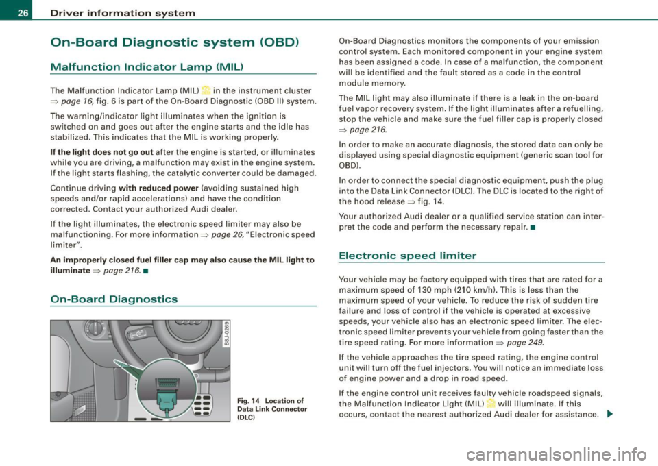
F ig . 14 L ocation of
Data Link Co nnector
( DL Cl
On -Board Diagnostics monitors the components of your emission
control system. Each monitored component in your engine system
has been assigned a code. In case of a malfunction, the component
will be identified and the fault stored as a code in the control
module memory .
The MIL light may also illuminate if there is a leak in the on -board
f ue l vapor recovery system. If the light i lluminates after a refuelling,
stop the vehicle and make sure the fuel filler cap is properly closed
=:>
page 216.
In order to make an accurate diagnosis, the stored data can only be
displayed using special diagnostic equipment (generic scan too l for
OBD).
In order to connect the special diagnostic equipment, push the plug
into the Data Link Connector (DLCl. The DLC is located to the right of
the hood release =:> fig . 14.
Your authorized Audi dealer or a qualified service station can inter
pret the code and perform the necessary repair. •
Electronic speed limiter
Your vehicle may be factory equipped with tires that are rated for a
maximum speed of 130 mph (210 km/h). This is less than the
maximum speed of your vehicle. To reduce the risk of sudden tire
failure and loss of control if the vehicle is operated at excessive
speeds, your vehicle also has an electronic speed limiter . The elec
tronic speed limiter prevents your vehic le from going faster than the
tire speed rating. For more in formation=:>
page 249.
If the vehicle approaches the tire speed rating, the engine control
unit will turn off the fue l injectors. You will notice an immediate loss
of engine power and a drop in road speed .
If the engine control unit receives faulty vehicle roadspeed signals,
the Ma lfunction Indicator Light (MIU will illuminate. If this
occurs, contact the nearest authorized Audi dealer for assistance.
~
Page 32 of 316
Driver inf ormation sy ste m
If Auto Check senses an irregu lar condition or a malfunction
requiring urgent repair, it generates a specific symbol or short message in the instrument cluster center display . You will also hear
an audible warning tone. The displays are color coded in either red
or yellow depending on their level of priority.
The red symbols indicate a
d angerou s conditio n which is addition
a lly signal led by
th ree warning tones. Whereas the ye llow symbols
represent a
W arning which is signalled by one warning tone. In
specific situations, messages for the driver appear in addition to the red symbols~
page 30. •
Driver information messages
Along with some particular warning/indic ator lights and
instrument cluster symbols, additional messages will
appear in the display .
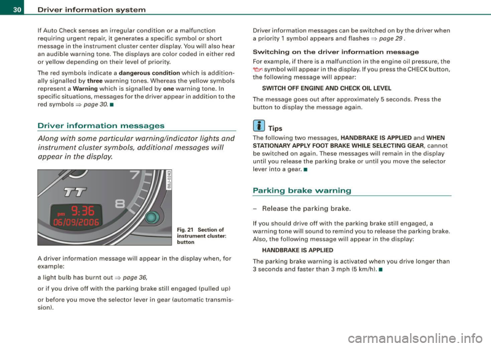
Fig. 21 Sectio n of
i n strum ent c luster:
b utton
A driver information message will appear in the disp lay when, for
example :
a light bulb has burnt out~
page 36,
or if you drive off with the parking brake still engaged (pulled up)
or before you move the se lector lever in gear (automatic transmis
sion). Driver information messages can be switched on by the driver when
a priority 1 symbo
l appears and flashes~
page 29.
Sw itc hing on th e driv e r inf orm ation m ess ag e
For example, if there is a malfunction in the engine oi l pressure, the
~ symbo l will appear in the display. If you press the CHECK button,
the fo llowing message will appear :
SWITCH O FF ENG IN E AND CHE CK OIL LE VEL
The message goes out after approximately 5 seconds. Press the
button to disp lay the message again.
[ i ] Tips
The fol lowing two messages, HANDBRAKE IS APPLIED and WHEN
S TA TIONARY APPLY FOOT BRA KE WHILE SELE CTIN G G EAR ,
cannot
be switched on again . These messages will remain in the display
until you release the parking brake or until you move the selector
l ever into a gear .•
Parking brake warning
- Release the parking brake.
If you should drive off with the parking brake still engaged, a
warning tone w ill sound to remind you to release the parking brake.
A lso, the following message will appear in the display:
HANDBR AKE IS APPLIED
The parking brake warning is activated when you drive longer than
3 seconds and faster than 3 mph (5 km/h). •
Page 40 of 316
Driver inf ormation sy ste m
[ i J Tip s
Even though your vehicle is equ ipped with a speed warning system ,
you should still watch the speedometer to make sure you are not
driving faste r than the speed limit. •
Speed warning 1 : setting a speed limit
Warning threshold 1 is set by the button.
Storing the ma ximum speed
Drive at the desired maximum speed.
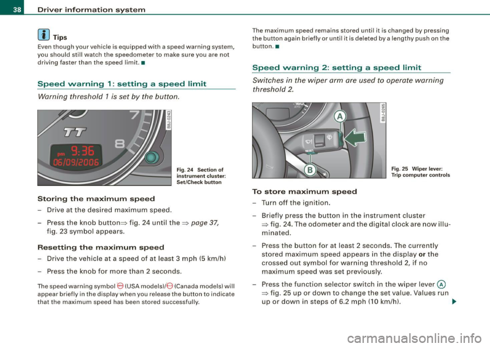
Fig . 2 4 Sec tio n of
in strum en t cl ust er:
Set/C hec k butto n
- Press the knob button~ fig. 24 until the ~ page 37,
fig. 23 symbol appears .
Resetting the max imum spe ed
- Drive the vehicle at a speed of at least 3 mph (5 km/h)
- Press the knob for more than 2 seconds .
The speed warning sy mbol 8 (USA models)/ 8 (Canada models) will
appear briefly in the d isplay when you release the button to indica te
that the maximum speed has been stored successfully . T
he maximum speed remains stored until it is changed by pressing
t he button again briefly or unti l it is dele ted by a lengthy push on the
but ton .•
Speed warning 2 : setting a speed limit
Switches in the wiper arm are used to operate warning
threshold 2.
To stor e maximum spee d
-Turn off the ignition.
Fig . 25 Wiper leve r:
T rip computer con tro ls
- Briefly press the button in the instrument cluster
=> fig. 24 . The odometer and the digital clock are now illu
mina ted .
- Press the button for at least 2 seconds. The currently stored maximum speed appears in the display
or the
crossed out symbol for warning threshold 2, if no
maximum speed was set previous ly.
- Press the function selector switch in the w iper lever @
=> fig. 25 up or down to c hange the set value . Va lues run
up or down in steps of 6 .2 mph (10 km/h). .,_