instrument cluster AUDI TT ROADSTER 2014 Owners Manual
[x] Cancel search | Manufacturer: AUDI, Model Year: 2014, Model line: TT ROADSTER, Model: AUDI TT ROADSTER 2014Pages: 244, PDF Size: 60.87 MB
Page 11 of 244
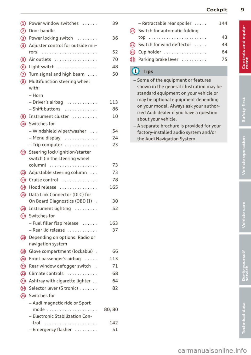
(!) Power window switches
@
®
©
Door handle
Power locking sw itch
Adjuster control for outside mir- rors ... . ............. .... .
® Air outlets ............... . .
@ Light switch . ... .... ... .. .. .
(J) Turn signa l and high beam . .. .
@ Mu ltifunction stee ring wheel
with:
- Horn
- Drive r's ai rbag .... ... .. .. .
- Shift buttons ..... ... .. .. .
® Instrument cluster
@ Sw itches for
- Windshield wiper/washer
- Menu disp lay ..... ... .. .. .
39
36
S2
70
48
so
113
86
10
S4
24
- T rip computer . . . . . . . . . . . . . 23
© Steering lock/ignition/starter
switch (in the steering wheel
column) . . . . . . . . . . . . . . . . . . . 73
@ Adjustab le s teer ing column . . . 73
@ Cruise control . . . . . . . . . . . . . . 78
€3J H ood re lease . . . . . . . . . . . . . . . 165
@ Data L ink Connector (DLC) for
On Board Diagnostics ( OBD II) 30
@ Instrument lighting . . . . . . . . . 52
@ Switches for
- Fuel filler flap release 163
- Rea r lid re lease . . . . . . . . . . . . 3 7
@ Depending on opt ions: Rad io or
nav igat ion system
@ Glove compar tment ( lockable) 66
@ Front passenger's a irbag . . . . . 113
@ Rear window defogger sw itch 7 1
@ Climate controls . . . . . . . . . . . . 68
@ Ashtray w ith cigarette lighter . . 64
@ Selecto r l ever (5 troni c) . . . . . . . 82
@) Switches for
- Audi magnet ic r ide or Sport
mode . . . . . . . . . . . . . . . . . . . . 80, 80
- Electronic Stab ilizat ion Con-
tro l . . . . . . . . . . . . . . . . . . . . . 142
- Emergency flasher . . . . . . . . . 51
Cockpi t 9
- Retractable rear spo iler .. ...
@ Switch for automatic folding
144
top . ... .. .. .. .. . .. .... ... .
@ Swi tch for wind deflector .... .
@ C up ho lder .. .. .. .......... .
@ Pa rking brake lever
(D Tips
- Some of the equipment or features
show n in the genera l illustration may be
standard equ ipme nt on your vehicle or
may be opt ional equ ipment depending
on you r model. Always as k yo ur au tho r
ized Aud i de aler if you have a quest ion
abou t your vehi cle.
- A separate bro ch ure is p rov ided for yo ur
facto ry-installed audio system and/or
the A udi Navigation System.
43
4 4
64
75
Page 12 of 244
10 Instruments and warning/indicator lights
Instruments and warning/indicator Lights
Instruments
Instrument cluster and controls
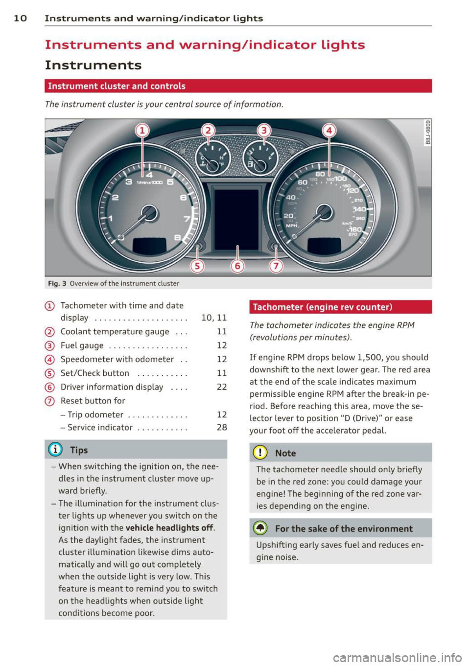
The instrument cluster is your central source of information.
Fig. 3 Overv iew of the inst rument cluster
(D Tachometer with time and date
dis play .. .... ..... ........ .
@ Coolant temperature gauge .. .
® Fuel gauge ................ .
© Speedometer with odometer ..
® Set/Check button ..... ... .. .
@ Driver information display
(?) Reset button for
- Trip odometer .......... .. .
- Service indicator
@ Tips
10 ,11
11
12
12
11
22
12
28
- When switching the ignition on, the nee
dles in the instrument cluster move up
ward briefly.
- The illumination for the instrument clus
ter lights up whenever you switch on the
i gnition with the
vehicle headlights off .
As the daylight fades, the instrument
cluster illumination likewise dims auto
matically a nd will go out completely
when the outside light is very low. This
feature is meant to remind you to switch
on the head lights when outside light
conditions become poor .
Tachometer (engine rev counter)
The tachometer indicates the engine RPM
(revolutions per minutes) .
en 0
~
~
"'
If engine RPM drops below 1,500, you should
downshift to the next lower gear. The red area
at the end of the scale indicates maximum
permissible engine RPM after the br eak-in pe
riod. Before reaching this area, move these
lector lever to position "D (Drive)" or ease
your foot off the acce lerator pedal.
(D Note
The tachometer needle should only briefly
be in the red zone: you could damage your
engine! The beg inning of the red zone var
i es depending on the engine.
@ For the sake of the environment
Upshifting early saves fuel and reduces en
gine noise.
Page 14 of 244
12 Instruments and warning/indicator lights
Fuel gauge
The fuel gauge works only when the ignition is
on . When the needle reaches the red area, the
warning light in the instrument cluster will il
luminate ¢
page 20 00']. Time to refuel!
The total ta nk capacity of your vehicle is listed
in
¢ page 224
CD Note
Never run the tank completely dry! An ir
regula r supply of fue l can cause engine
m isfiri ng and fuel could enter into the ex
haust system. The catalyt ic converter
could then overheat and be damaged.
Speedometer with odometer
The speedometer shows you the vehicle
speed , and the odometer shows you how
many miles (kilometers) you have driven.
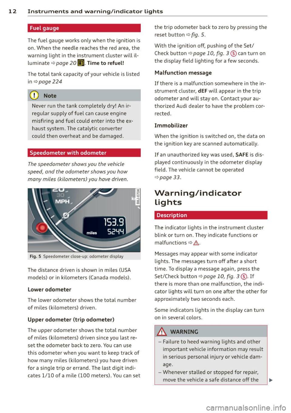
Fig . S Spee domete r close -up: odometer display
The dis tance driven is shown in miles (USA
models) or in kilometers (Canada models) .
Lower odometer
The lower odometer shows the total number
of miles (kilometers) driven.
Upper odometer (trip odometer)
The upper odometer shows the total number
of mi les (kilometers) driven since you last re
set the odometer back to zero. You can use
this odometer wh en you want to keep track of
how many miles (kilometers) you have driven
for a sing le trip or errand. The last digit indi
ca tes 1/10 of a mile (100 me ters). You can se t the trip odometer
back to zero by pressing the
reset button
¢ fig. 5.
With the ign ition off, pushing of the Set/
Check button ¢
page 10, fig . 3 ® can turn on
the display fie ld lighting for a few seconds.
Malfunction message
If there is a malfunct ion somewhere in the in
strument cluster,
dEF will appear in the trip
odometer and will stay on. Contact your au
thorized Audi dea ler to have the problem cor
rected .
Immobilizer
When the ignition is sw itched on, the data on
the ignition key are scanned automat ically .
If an unauthor ized key was used,
SAFE is dis
played continuously in the odometer display
field . The vehicle cannot be operated
¢ page 33.
Warning/indicator
Lights
Description
T he ind icator lights in the instrument cluster
blink or turn on . They indicate funct ions or
malfunctions ¢
,&.
Messages may appear with some indicator
lights . The messages turn
off after a short
time . To display a message again, press the
Set/Check button¢
page 10, fig . 3 ® · If
there is more than one ma lfunction, the indi
cator lights will turn on one after the other for
approximat ely two seconds each.
Some indicators lights in the display can turn
on in severa l colors.
A WARNING
=
- Failure to heed warning lights and other
important vehicle information may result
in ser ious personal in jury or vehicle dam
age.
- Whenever stalled or stopped for repair,
move the vehicle a safe distance
off the
Page 21 of 244
Instrument s and warnin g/indic ator ligh ts 19
-USA models: If the la warning light,
the
G1 warning light and the m:IJ warn
ing light come on together, t he rear
wheels could lock up first under hard
braking. Rear wheel lock-up can cause
loss of vehicle control and an accident .
Have your vehicle repai red immediately
by you r autho rized Aud i dea ler or a qua li
fied workshop. Drive slowly and avoid
sudden, hard brake applications .
-Canada models: If the brake warn ing
light ., the
&J warn ing light and the
ABS warning light
[IJ come on together,
the rear wheels could lock up first under
hard braking. Rear wheel lock-up can
cause loss of vehicle control and an acci
dent . Have you r vehicle repaired immed i
ately by your authorized Audi dealer or a
qualified wo rkshop . Dr ive slowly and
avo id sudden, hard brake applicat ions.
( 0) Worn brake pads
riJ Che ck brake pad s!
If the warn ing light illum inates, immediately
contact your authorized A udi dealer or quali
f ied workshop to have all brake pads inspect
ed. O n USA models the wa rning lig ht
riJ
comes on togethe r wi th the warn ing light
la . Both sets of b ra ke pads on an axle
must always be replaced at the same time .
A WARNING
Driving with bad brakes can cause a colli
sion and serious personal injury.
- If the warning light riJ and the warning
light
lai1 ) w it h the message Brake
pads !
comes on in the instr ument cluster
display, immediately contact your au
tho rized Aud i dea le r or qualified work
shop to have a ll brake pads checked or
replaced if necessary .
1) - : USA mod els on ly
-
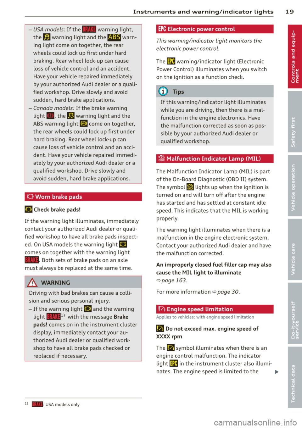
EPC Electronic pow er control
This warning/indicator light monitors the
electronic power control.
The ~ warning/indicator light (Electronic
Power Control) illuminates when you switch
on the ignition as a function check .
@ Tips
If this warning/ indicato r light illum inates
while you are driving, then there is a mal
funct ion in the engine electronics . Have
the malfunct ion corrected as soon as pos
sible by your authori zed A udi dealer or
q ualified works hop .
~ Malfunction Indicator lamp (MIL )
The Ma lfun ction Indicator Lamp ( MIL) is par t
of the On -Board Diagnostic (OBD II) system.
The symbo l
fl lights up when the ignition is
turned on and will turn off after the eng ine
has started and has settled at constant idle
speed . This indicates that the MIL is work ing
proper ly.
The warning light illuminates when there is a
malfu nction in the eng ine electron ic system .
Contact your a uthorized Audi dea ler and have
the malfunction corrected.
An improperly closed fuel filler cap may also
cause the MIL l ight to illum inate
c::> page 163.
For more information c::> page 30 .
!?) Engine speed limitation
App lies to vehicles : wi th engine speed limitatio n
(m Do not e xceed ma x. engine speed of
XXXX rpm
The (Ill symbol illuminates when there is an
engine contro l ma lf u nction . The indicator
li ght ~ in the instrument cl uster a lso illumi-
nates. The engine speed is limited to the .,.
Page 30 of 244
28 Driver information system
Fue l economy messages are displayed when
fuel consumption is increased by certain con
ditions. If you follow these fuel economy mes
sages, you can reduce your vehicle's consump
t ion of fuel. The messages appear automati
cally and are only displayed in the efficiency
program . The fuel economy messages turn off
automatically after a certain period of time .
.,. To turn a fuel economy message off immedi
ately after it appears, press the
! R ESET I but
ton
¢ page 24 , fig . 1 O @, or
.,. Press the function selection switch
¢page 24, fig.10 @.
(D Tips
-Once you have turned a fuel economy
message off, it will only appear again af
ter you turn the ignition on aga in.
- The fuel economy messages are not dis
played in every instance, but rather in in
tervals over a period of ti me.
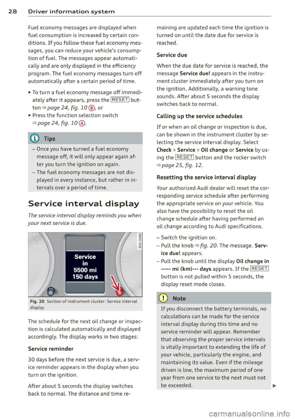
Service interval display
The service interval display reminds you when
your next service is due.
Fig. 20 Sectio n of inst rume nt cl uster : Serv ice interv al
d isplay
The schedule for the next oil change or inspec
tion is calculated automatically and displayed
according ly . The display works in two stages :
Service reminder
30 days before the next service is due, a serv
ice rem inder appears in the display when you
turn on the ignition.
After about 5 seconds the display sw itches
back to normal. The d istance and time re- maining are
updated each time the ignition is
turned on until the date due for service is
reached.
Service due
When the due date for service is reached, th e
message
Service due! appears in the instru
ment cluster immediately after you turn on
the ignition . Additionally, a warning tone
sounds. After about 5 seconds the disp lay
switches back to normal.
Calling up the service schedules
If or when an oil change or inspection is due,
can be shown in the instrument cluster by se
lecting the service interval display . Select
Chec k > Service > Oil change or Service by us
ing the
I RESET I button and the rocker switch
r:::> page 25, fig. 12 .
Resetting the service interval display
Your authorized Audi dealer will reset the cor
responding service schedule after performing
the appropriate service on you r vehicle. You
also have the possibility to reset the oil
change schedule after having performed an
o il change according to Audi specif ications.
- Switch the ignition on.
- Pull the knob
r:::> fig. 20. The message. Serv-
ice due!
appears.
- Pull the knob until the display
Oil change in
-----mi (km)--- days appears . If the I RESET I
button is not pulled within 5 seconds, the
display reset mode closes.
(D Note
If you disconnect the battery terminals, no
calculations can be made for the service
interval display dur ing this time and no
serv ice reminder will appear. Remember
that observing the proper service intervals
i s vitally important to extending the life of
your vehicle, pa rticularly the engine, and
maintaining its value. Even if the mileage
driven is low, the maximum period of one
year from one service to the next m ust not
be exceeded.
II>-
Page 32 of 244
30 Driver information system
Evaluating times and continuing or
resetting timing
Applies to vehicles: with lap timer
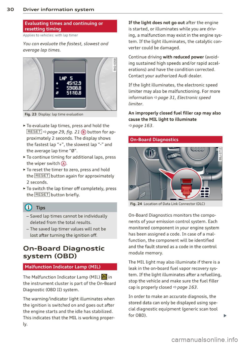
You can evaluate the fastest, slowest and
average lap times.
LAP 5
+ 45:12.9
59:08.8
0 51 :10.a
Fig. 23 Display: lap time eval uation
.. To eva luate lap times, press and hold the
I RESET Ir=) page 29, fig . 21 @ button for ap
proximate ly 2 seconds. The display shows
the fastest lap" +", the s lowest lap"-" and
the average lap time
"0" .
.. To continue t iming for addit ional laps, press
the wiper switch @ .
.. To reset the timer to zero , press and hold
the
I RESET I button again for approximately
2 seconds .
.. To switch the lap timer off comp letely, press
the
I RESET ! button briefly.
(D Tips
- Saved lap times cannot be individually
deleted from the tota l resu lts.
- The saved lap timer values will not be
l os t after turning the ignition off.
On-Board Diagnostic
system (OBD)
Malfunction Indicator Lamp (MIL)
The Malfunction Indicator Lamp (M IL) Iii in
the instrument cluster is part of the On-Board
Diagnostic (OBD
II) system.
The warning/indicator ligh t illuminates whe n
the ignition is switched on and goes out after
the eng ine starts and the idle has stabilized.
This indicates that the MIL is working proper
ly .
If the light does not go out after t he engine
is started, or illuminates while you are driv
i ng, a malfunction may exist in the eng ine sys
tem. If the light illuminates, the catalytic con
verter could be damaged .
Contin ue driving
with reduced power (avoid
i ng sustained high speeds and/or rapid accel
erations) and have the cond ition corrected.
Contact your a uthorized Audi dea ler.
If the light il luminates, the electronic speed
limiter may also be malfunct ioning. For more
information
c:> page 31, Electronic speed
limiter.
An improperly closed fuel filler cap may also
cause the MIL light to illuminate
c:> page 163.
On-Board Diagnostics
Fig. 24 Locat ion of Data Link Connector (DLC)
On-Board Diagnostics monitors the compo
nents of your emission contro l system . Each
monitored component in your engine system
has been assigned a code. In case of a mal
funct ion, the component will be identified
and the fault stored as a code in the control
module memory.
The MIL light may also illuminate if there is a
leak in the on-board fuel vapor recovery sys·
tem. If the light illuminates after a refuelling,
stop the vehicle and make sure the fuel filler
cap is properly closed
c:> page 163.
In order to make an accurate diagnosis, the
stored data can on ly be displayed using spe
c ial dia gnost ic equipment (generic scan tool
furOBD) .
~
Page 40 of 244
38 Openin g and clo sing
well as the vehicle doors closed when not
in use.
@ Tips
- If the rear lid is ope n or not properly
locked when the ignition is turned on,
the door and rear lid warning appears in
the instrument cluster disp lay.
- If the rear lid on a locked vehicle is un
locked with the middle button
c;j on the
remote key, the rear lid is automatically
l ocked again immediately after clos ing .
This is indicated by the turn signals blinking .
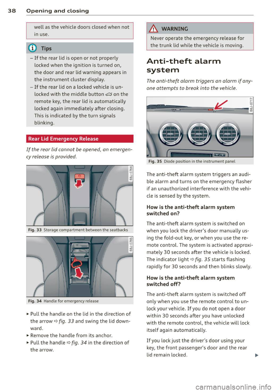
Rear Lid Emergency Release
If the rear lid cannot be opened , an emergen
cy release is provided .
Fig. 33 Storage compartment between t he seatbacks
Fig. 3 4 Handle for emergency re lease
., Pull the hand le on the lid in the d irect ion of
the arrow
i=;, fig. 33 and swing the lid down
ward .
.. Remove the handle from its anchor.
.. Pull the hand le
r::;, fig. 34 in the direction of
the arrow.
A WARNING
-Never operate the emergency release for
the trunk lid while the vehicle is moving .
Anti-theft alarm
system
The anti -the~ alarm triggers an alarm if any
one attempts to break into the vehicle.
F ig . 35 D iode positio n in th e instr ument pane l
,..
-q
i
The anti-theft alarm system triggers an audi
ble a larm and turns on the emergency flasher
if an unauthorized interference with the vehi
cle is sensed by the system .
How is the anti- theft ala rm sy ste m
sw itched on ?
The anti-theft alarm system is switched on
when you lock t he driver's door manually us
ing the fold-out key, or when you use the re
mote control. The system is activated approx i
mately 30 seconds after the vehicle is locked.
T he ind icator light
r::;,fig. 35 starts flashing
rapid ly for 30 seconds and then bl inks slowly .
How is th e anti-theft alarm sy stem
sw itched off?
T he anti-theft alarm system is switched off
o nly when you use the remote control to un
lock your vehicle . If you do not open a door
within 30 seconds after you have unlocked
with the remote control, the vehicle wi ll lock
itself aga in automatically .
If you lock just the driver's door using your
key, the front passenger's door and the rear
lid remain locked. ..,.
Page 49 of 244
opening for the eme rgency locking crank is
l ocated behind the protective cap.
Removing the square shaft
.,. Insert the threaded side of the crank into
the insertion opening
q fig. 52 .
.,. Turn the crank to the right until it is tightly
screwed into place@ .
.,. Pull the crank with the square shaft thread
ed onto it downward to remove the shaft
completely @.
Using the crank to lock the convertible
top
.,. Insert the other side of the crank (with the
mult ipoint head) into the opening until the
stop ring lies against the closing mo tor @
qfig . 52 .
.,. Turn the crank clockwise to open the retain
ers and pull the convertible top down at the
s ide .
.,. Turn the crank counter-clockwise until the
top is fully locked in place and the indicator
light on the instrument cluster goes out .
.,. Pull the crank out.
.,. Unscrew the square shaft from the crank .
.,. Insert the square shaft into the opening un
t il you hear it click into place .
.,. Use the protective cap to close off the inser -
t ion open ing .
The convertible top is now completely closed .
H ave the malfunct ion repaired as soon as pos
sible.
(Dl Tips
Turn the emergency operat ion screw in the
luggage compartment to the r ight to close
the convertible top hydraulic system.
Convertible top 47
Page 50 of 244
48 Clear vision
Clear vision Lights
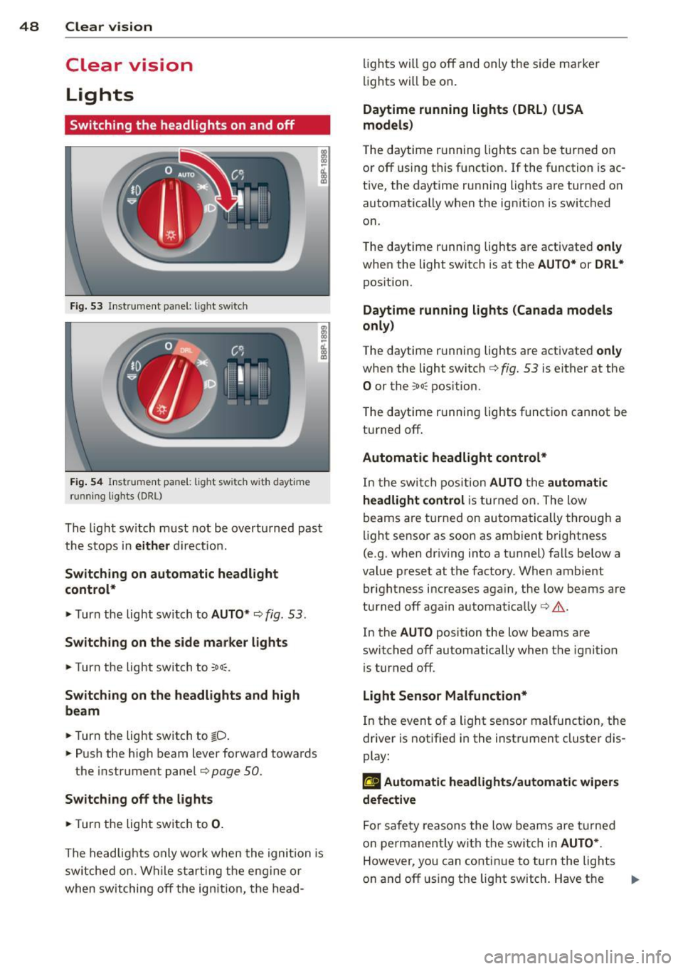
Switching the headlights on and off
Fig . 53 Instr ument pane l: light sw itch
Fig. 54 Instr ument pane l: ligh t switch w ith dayti me
running lights (DR L)
The light switch must not be overturned past
the stops in
either direct ion.
Switching on automatic headlight
control*
.,. Turn the light switch to AUTO* ¢ fig. 53.
Switching on the side marker lights
... Turn the light switch to :;oo:.
Switching on the headlights and high
beam
... Turn the light switch to iD.
... Push the high beam lever forward towards
the instrument panel¢
page SO.
Switching off the lights
... Turn the light switch to 0.
The head lights only work when the ignition is
switched on. While start ing the engine or
when switching off the ignition, the head- lights
will go off and only the side ma rker
lights will be on.
Daytime running lights (DRL) (USA
models)
T he daytime running lights can be turned on
or off using this function. If the function is ac
tive, the daytime running lights are turned on
automatically when the ignit ion is switched
on.
The daytime running lights are activated
only
when the light switch is at the AUTO* or DRL *
position.
Daytime running lights (Canada models
only)
The daytime running lights are activated only
when the light switch ¢ fig. 53 is either at the
0 or the :;oo: position.
T he daytime r unning lights funct ion cannot be
turned off.
Automatic headlight control*
In the switch position AUTO the automatic
headlight control
is turned on. The low
beams are turned on automatically through a
light sensor as soon as ambient brightness
(e .g. when driving into a tunnel) falls below a
value preset at the factory. When ambient
brightness increases aga in, the low beams are
turned off again automatically ¢.&. .
In the
AUTO position the low beams are
switched off automatically when the ignition
is turned off .
Light Sensor Malfunction*
In the event of a light sensor malfunction, the
driver is notified in the instrument cluster dis
play:
El Automatic headlights/automatic wipers
defective
For safety reasons the low beams are turned
on permanently with the switch in
AUTO* .
However, you can continue to turn the lights
on and off using the light switch. Have the
Ill>-
Page 52 of 244
50 Clear vis ion
Front fog lights
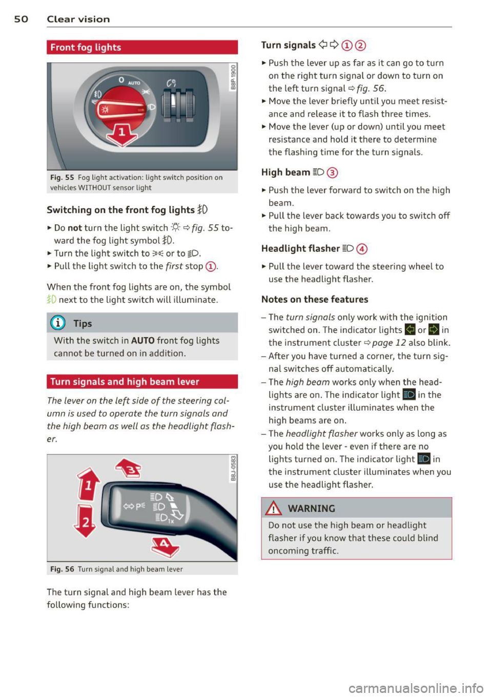
F ig. 55 Fog light act ivation: light switch pos itio n on
veh icles WITHOUT sensor light
Switching on the front fog lights iO
.,. Do no t turn the light switch ·'t/- · ¢ fig. 55 to-
ward the fog light symbol
}D.
.,. Turn the light switch to :o o: or to io .
.,. Pull the ligh t switch to the first stop @.
When the front fog lights are on, the symbol
}D next to the light switch will i llum ina te.
@ Tips
With the switch in AUTO front fog lights
cannot be turned on in addit ion.
Turn signals and high beam lever
The lever on the left side of the steering col
umn is used to operate the turn signals and
the high beam as well as the headlight flash
er .
Fig. 56 Tu rn signa l and hig h beam lever
The turn signal and high beam lever has the
following functions:
Turn signals ¢ Q ©@
.,. Push the lever up as fa r as it ca n go to t urn
on the right turn s ignal or down to tu rn on
the left turn signal ¢
fig. 56 .
.,. Move the lever briefly unti l you meet res ist
ance and release it to flash three times .
.,. Move the lever (up or down) until you meet
resistance and hold it there to determine
the flashing time for the turn signals .
High be am gD @
.,. Push the lever forward to switch on the high
beam.
.,. Pull the lever back towards you to switch off
the high beam.
Headlight fla sh er gD @
.,. Pull the lever toward the steering whee l to
use the headlight flasher.
Not es on thes e features
- The turn signals on ly work wi th the ignition
sw itched on. The indicator lights
F-1 or rl in
the instrument cluster¢
page 12 also blink.
- After you have turned a co rner, the turn s ig-
na l switches off automa tically .
- The
high beam works on ly w hen the he ad
lights a re on . The indicator light
II in t he
instrument cluster illuminates when the
high beams are on.
- The
headlight flasher works only as long as
you ho ld the lever - even if there a re no
lights turned on. The indicator light
II in
the instrument cluster illuminates when you
use the headlight flasher.
A WARNING
-
Do not use the h igh beam or head light
flasher if yo u know that these could b lind
oncom ing traffic.
-