display AUDI TT ROADSTER 2015 Owner's Manual
[x] Cancel search | Manufacturer: AUDI, Model Year: 2015, Model line: TT ROADSTER, Model: AUDI TT ROADSTER 2015Pages: 244, PDF Size: 60.74 MB
Page 54 of 244
52 Clear vis ion
Instrument panel illumination
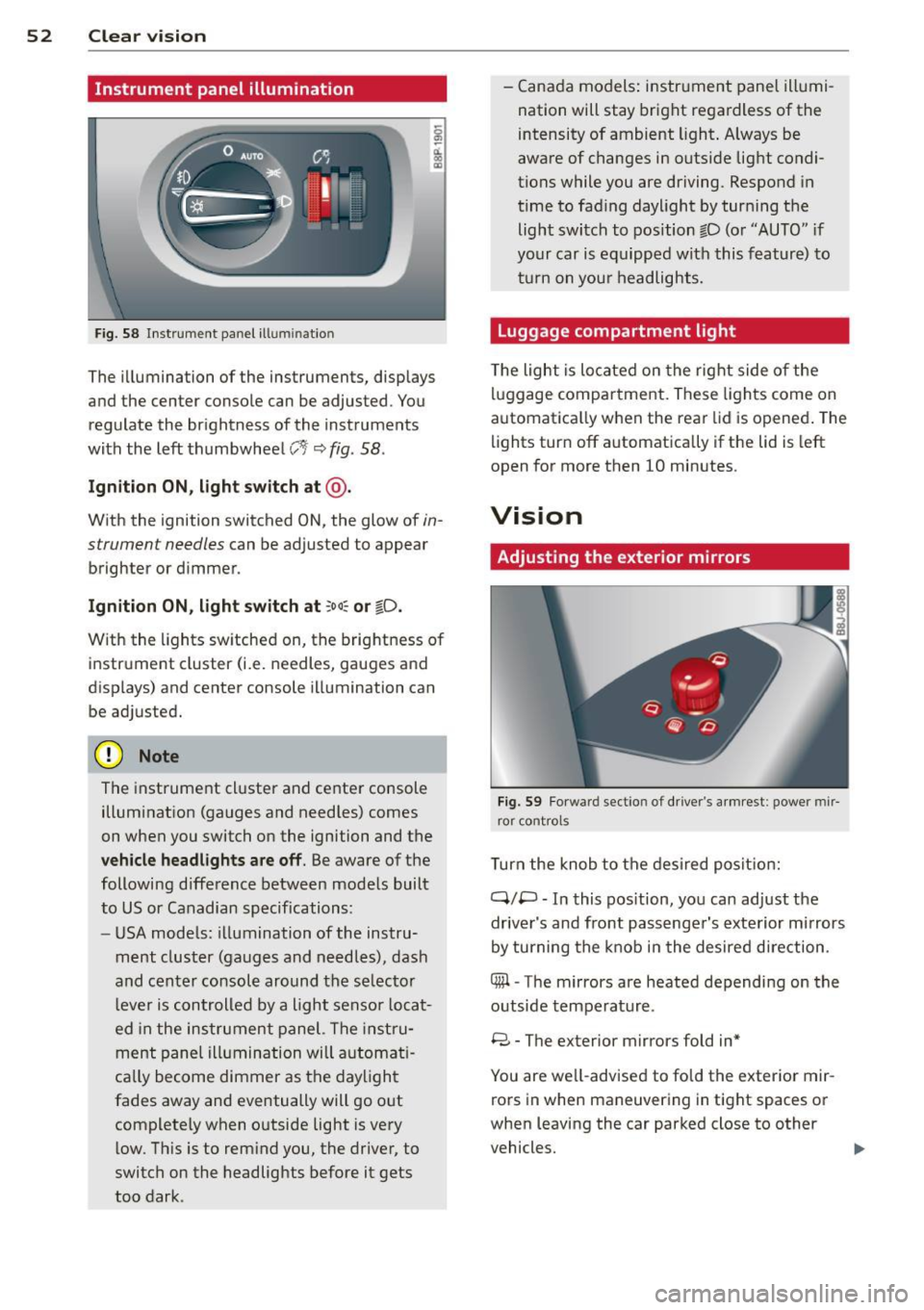
F ig. 58 Instrument panel ill umination
The illumination of the instruments, displays
and the center console can be adjusted. You
regulate the brightness of the instruments
with the left thumbwheel
CJ:J ~ fig. 58.
Ignition ON, light switch at @ .
With the ignition switched ON, the glow of in
strument needles can be adjusted to appear
brighter or dimmer.
Ignition ON , light switch at ;oo~ or io .
With the l ights sw itched on, the brightness of
instrument cluster (i.e. needles, gauges and
displays) and center console illumination can
be adjusted.
@ Note
The instrument cl uster and cente r console
illumination (gauges and needles) comes
on when you switch on the ignition and the
vehicle headligh ts ar e off . Be aware of the
following difference between mode ls built
to US or Canadian specifications:
- USA mode ls: illumination of the instru
ment cluster (gauges and needles), dash
and center consol e around the se lector
l ever is controlled by a light senso r locat
ed in the instrument panel. The instru
ment pane l illumination will a utomat i
cally become dimmer as the daylight
fades away and eventually will go out
complete ly when outside light is very
l ow . Th is is to rem ind you, the driver, to
switch on the headlights before it gets
too dark . -
Canada models: instrument panel illumi
nation will stay bright regardless of the
intensity of ambient light . Always be
aware of changes in outside light condi
tions while you are driving. Respond in
time to fading daylight by tur ning the
light switch to position fD (o r "AUTO" if
your car is equipped with this feature) to
t ur n on you r headlights.
Luggage compartment light
The light is located on the right side of the
lu ggage compartme nt. These lights come on
automat ica lly when the rear lid is opened . The
lights turn off automatica lly if the lid is left
open for more then 10 minutes.
Vision
Adjusting the exterior mirrors
Fig. 59 Fo rwa rd section of driver's a rmrest: power mir
ror controls
Turn the knob to the desired posit ion:
Q/ P -In this pos ition, you can adjust the
driver's and front passenger's exte rior m irrors
by turning the knob in the desired d irection.
4iil -The mirrors are heated depending on the
outside temperature .
8 -The exterior mirrors fold in*
You are we ll-advised to fold the exterior mir
rors in when maneuvering in tight spaces or
when leaving the car parked close to other
vehicles. ..,,.
Page 58 of 244

56 Clear vis ion
The washer jets extend forward out o f the
front bumper driven by water pressure to
spray the front headlights with water.
You shou ld inspect the headlights regularly
(for example when refueling) and clean
off
any solid dirt or insects from the lenses .
To ensure the system wo rks properly in wi nter,
keep the washer jets free of snow and remove
any ice using a de-icing spray.
Service position
It is only possible to change wiper blades if
you move the wiper arms to the service posi
tion .
In o rder to use the windsh ield wipers, t he
front lid mus t be comp lete ly closed.
Moving w iper blades to the service
position
• When there is a risk of frost, make s ure that
the wiper b lades a re not frozen to the wind
shield .
.. Switch the ignition on.
.. Move the wiper lever to position
0
c> page 54, fig. 62.
.. Press the I Reset I button until the Displa y
typ e
menu appears in the Driver Informa
t ion System display .
.. Us ing the rocker switch and the
! Reset ! but
ton, select the
S et > W iper s > Front > Serv
ice positi on on
function. The winds hield
wiper arms move to the service position.
Moving wiper blades to park position
.. Make certain that the wiper arms are lying
against the windshie ld .
.. Switch the ign ition on and move t he wiper
l ever from posi tion
O to 4 c> page 54,
fig . 62 .
The wiper arms will move back to
the park position.
«I) Note
Never drive yo ur vehicle when the w ind
shie ld w iper arms are in the service pos i
tion and pulled away from the windshie ld .
When you dr ive faste r than 4 mp h (6 km/ h), the wiper a
rms automatically return to
the park position and cou ld cause paint
damage to the front lid!
(D Tips
- Yo u can also turn on the se rvice posit ion,
for example, if yo u want to protect the
w indshield from icing by using a cover .
- The service posit ion moves to
off a uto
matically when you operate the w ind
shield wiper lever, or speed exceeds
4 mph (6 km/h).
Cleaning windshield wiper blades
Clean the windshie ld w iper blades when they
begin to leave streaks. Use a soft cloth and
glass cleaner to clean the windshield wiper
blades.
.. Place the windshie ld w iper arms in the serv
ice pos it ion . Refer to
c::> page 56 .
"' Lift the wiper arm away from the front win
dow.
_&. WARNING
Di rty windsh ield wiper b lades can impair
your view. This can lead to accidents .
-
Page 60 of 244
58 Clear vision
-To help prevent damage to the wiper
arms or oth er components, do not at
tempt to move the wipers by hand.
@ Tips
- Commercial hot waxes applied by auto
matic car washes aff ect the cleanability
of the glass surface .
- The front wiper blades are different
lengths; the blade on the driver's side is
longer .
Digital compass
Activating or deactivating the compass
Applies to vehicles: with digital compass
Fig. 65 Inside re ar view mirro r: di gital compass ac ti
va ted
• To activate or deactivate , hold the@
¢ fig. 65 button down until the red display
appears or disappears.
The digital compass only works with the igni
tion turned on . The directions are displayed as
initials:
N (North), NE (Northeast) , E (East),
SE (Southeast) , S (South), SW (Southwest),
W (West), NW (Northwest).
The compass has to be recalibrated if the dis
play is wrong or inaccurate
¢ page 58.
(j) Tips
-To avoid inaccurate directions, do not al
low any remote controls, electrical sys
tems, or metal parts close to the mirror.
- The correct magnetic deflection zone
must be set in order to display the direc
tions correctly.
Setting the magnetic deflection zone
Applies to vehicles: with digital compass
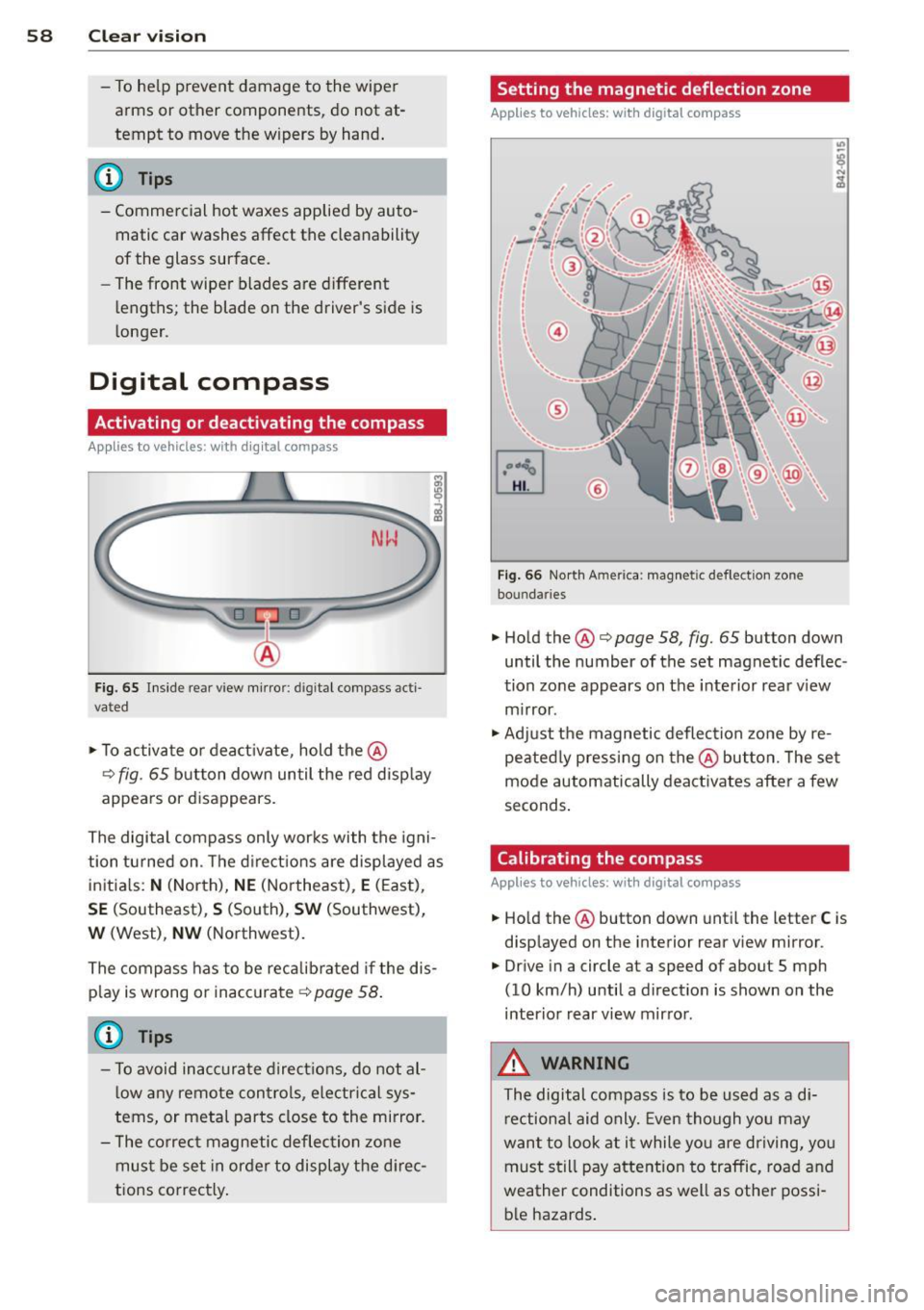
Fig. 66 North A meri ca : magn etic defle ction zo ne
bo undaries
• Hold the@¢ page 58, fig. 65 button down
until the number of the set magnetic deflec
tion zone appears on the interior rear view
mirror .
• Adjust the magnetic deflection zone by re
peatedly pressing on the@button. The set
mode automatically deactivates after a few
seconds.
Calibrating the compass
Applies to vehicles: with digital compass
• Hold the @button down until the letter C is
displayed on the interior rear view mirror .
• Drive in a circle at a speed of about S mph
(10 km/h) until a direction is shown on the
interior rear view mirror.
_&. WARNING
The digital compass is to be used as a di
rectional aid only. Even though you may
want to look at it while you are driving, you
must still pay attention to traffic, road and
weather conditions as well as other possi
ble hazards.
-
Page 78 of 244
![AUDI TT ROADSTER 2015 Owners Manual 76 On the road
ignition, assum ing that you have not changed
or reset the setting.
The speed warning symbo l
ID] (USA models)/
1aj (Canada models) in the warning 1 displ ay
appears AUDI TT ROADSTER 2015 Owners Manual 76 On the road
ignition, assum ing that you have not changed
or reset the setting.
The speed warning symbo l
ID] (USA models)/
1aj (Canada models) in the warning 1 displ ay
appears](/img/6/57664/w960_57664-77.png)
76 On the road
ignition, assum ing that you have not changed
or reset the setting.
The speed warning symbo l
ID] (USA models)/
1aj (Canada models) in the warning 1 displ ay
appears when you exceed the maximum
speed. It goes o ut when the speed fa lls below
the stored max imum speed .
The speed wa rning symbo l w ill also go out i f
the speed
exceeds the sto red max imum speed
by more than about 25 mph (40 km/h) for at
l east 10 seconds. The stored maxim um speed
is deleted .
Sett ing speed warning 1
¢page 76 .
Speed warning 2
Sto ring warning 2 is re commended if you al
ways
want to be reminded of a certa in speed,
for exam ple when yo u are traveling i n a cou n
try th at has a general maximum speed limi t,
or if you do not want to exceed a specified
speed for winter tires.
The speed w arning 2 symbol,
lDJ (USA mod
e ls)/
lDJ (Canada models) appea rs in the dis
p lay when you exceed the stored speed limit .
Unlike warning 1, it will not go out unti l th e
vehicle speed drops below the stored speed limit.
Setting s peed warn ing 2
¢ page 77 .
@ Tips
Even t hough your vehicle is equ ipped wi th
a speed w arni ng sys tem, yo u shou ld st ill
watch the s peedomete r to make sure you
are not driving faster than the speed lim it.
Speed warning 1: setting a speed limit
Warning threshold 1 is set by the button .
Fig. 8 3 Sectio n of instru ment clus ter: Set/C heck b ut
to n
Storing the max imum speed
.,. Dr ive at the desired ma ximum speed.
.,. Press the knob buttonc>fig .
83 unti l the
speed warn ing
symbo1 1m1 (U SA mode ls)/ 181
(Canada models) appears.
Resetting the maximum speed
.,. Dr ive the veh icle at a spee d of at least
3 mph ( 5 km/h)
.,. Press the knob for more than 2 seconds.
T he speed warning symbol
ID] (USA mode ls)/
k•j
cate that the maximum speed has been stored
s uccessfully .
The maxim um speed remains stored until it is
c h anged by pressing the button aga in b rief ly
or unt il it is deleted by a lengthy push on the
button.
Page 79 of 244
Speed warning 2: setting a speed limit
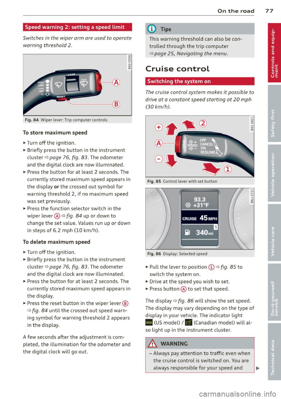
Switches in the wiper arm are used to operate warning threshold
2 .
'----I ®
Fig. 84 W iper lever: Trip computer controls
To store maximum speed
.. Turn off the ignit ion .
.. Briefly press the button in the instrument
cluster¢
page 76, fig. 83. The odometer
and the digital clock are now illuminated .
.. Press the button for at least 2 seconds. The
currently stored maximum speed appears in
the display
or the crossed out symbol for
warning threshold 2, if no maximum speed
was set previously .
.. Press the function selector switch in the
wiper lever@¢
fig. 84 up or down to
change the set value. Values run up or down
i n steps of 6.2 mph (10 km/h).
To delete maximum speed
.. Turn off the ignition.
.. Briefly press the button in the instrument
cluster ¢
page 76, fig. 83. The odometer
and the digital clock are now illuminated.
.. Press the button for at least 2 seconds. The
currently stored maximum speed appears in
the display.
.. Press the reset button in the wiper lever®
¢
fig . 84 until the crossed out speed warn
ing symbol for warning threshold 2 appears
in the d isplay.
A few seconds after the adjustment is com pleted, the illumination for the odometer and
the digital clock will go out.
On the road 77
@ Tips
This warning threshold can a lso be con
trolled through the trip computer
¢ page 25, Navigating the menu.
Cruise control
Switching the system on
The cruise control system makes it possible to
drive at a constant speed starting at
20 mph
(30kmlh).
®-
Fig. 85 Co ntro l leve r w ith set b utto n
Fig. 86 Display : Se lected speed
.. Pull the lever to position @¢ fig. 85 to
switch the system on .
.. Dr ive at the speed you w ish to set .
.. Press button @ to set that speed.
The display ¢
fig. 86 will show the set speed .
The display may vary depending on the type of
display in your vehicle. The indicator light
II (US model) /. (Canadian model) will al
so light up in the instrument cluster .
A WARNING
-Always pay attention to traffic even when
the cruise control is switched on. You are
always responsible for your speed and
Page 83 of 244
Transmission S tronic transmission
Introduction
Your vehicle is equipped with a S tronic trans miss ion, also called a double-clutch system/
transmission.
Power is transferred between the engine and
the transmission by means of two i ndepend
ent clutches. They replace the to rque convert
e r of conventional automat ic transm iss ions
and a llow the vehicle to acce lerate without a
noticeable break in the power flow .
W ith the aid
of tiptr oni c, the gea rs can op
tionally be sh ifted
manually¢ page 84.
Selector lever positions
All the selector lever positions are explained
in this section.
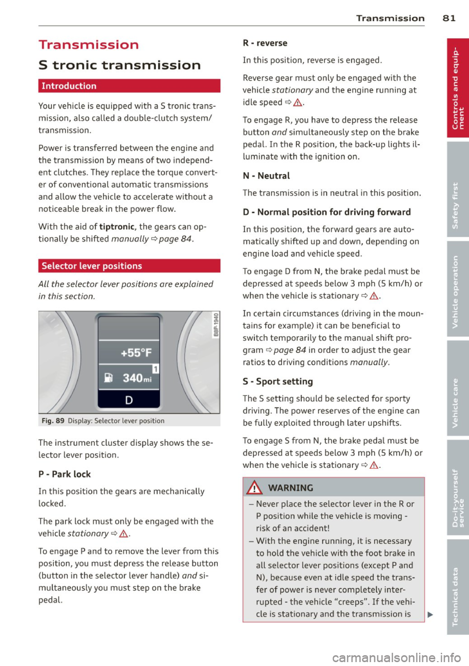
F ig . 89 Display: Selector lever position
The instrument cluster display shows these
l ector lever position.
P -Park loc k
In th is position the gea rs are mechan ically
l ocked .
The park lock must on ly be engaged with the
ve hicle
stationary¢ /1. .
To engage P and to remove the lever from th is
position, you must depress the release button
(button in the selector lever handle)
and si
multaneously you must step on the brake
pedal.
Tran sm iss ion 8 1
R -re ver se
In this position, reverse is engaged.
Reverse gear must only be engaged w ith the
vehicle
stationary and the engine ru nning at
idle speed ¢
/1..
To engage R, you have to depress the release
button
and simultaneously step on the brake
pedal. I n the R pos ition, the bac k-up lights il
luminate w ith the ignition on.
N -Neutral
The transm iss ion is in neutral in this pos ition.
D -Normal po sition fo r dri ving fo rward
In this position, the forward gears are auto
matically shifted up and down, depending on
engine load and vehicle speed.
T o engage D from
N, the brake pedal must be
depressed at speeds below 3 mph (5 km/h) or
when the vehicle is stationary¢&. .
In certa in circ umstances (driving in the moun
tains for examp le) it can be beneficia l to
switch temporari ly to the man ual shift pro
gram ¢
page 84 in order to adjust the gear
ratios to driving conditions
manually .
S -Sport setting
The S set ting should be se lected for sporty
driving. The power reserves of the engine can
be fully exploited through later upshifts.
T o e ngage 5 from N, the b rake peda l must be
depressed at speeds below 3 mph (5 km/h) or
when the vehicle is stationary¢&. .
A WARNING
-Never p lace the selector lever i n the R or
P posit ion while the veh icle is moving -
risk of an accident!
- With the engine r unning, it is necessary
to hold the vehicle with the foot brake in
all se lector lever positions (except P and
N), because even at idle speed the trans
fe r of power is never completely inter
r u pted -the vehicle "creeps". If t he vehi
cle is stat io nary and the transm ission is
Page 87 of 244
If you have selected a lower gear than the cur
rent one, the transmission will only shift down
when the engine cannot be overspeeded .
If kick-down is actuated, the transmission
shifts into a lower gear independent ly of
speed and engine rpm .
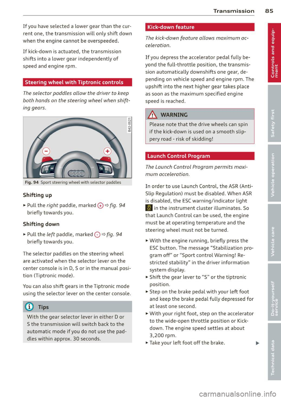
Steering wheel with Tiptronic controls
The selector paddles allow the driver to keep
both hands on the steering wheel when shift
ing gears.
Fig. 94 Sport stee ring wheel with selecto r paddles
Shifting up
.,. Pull the right paddle, marked 0 ¢ fig. 94
briefly towards you .
Shifting down
.. Pull the left paddle, marked 0 ¢ fig. 94
briefly towards you.
The selector paddles on the steering wheel
are activated when the selector lever on the
center console is in D, Sor in the manual posi
tion (Tiptronic mode).
You can also shift gears in the Tiptronic mode
using the selector lever on the center console.
@ Tips
With the gear selector lever in either Dor
S the transmission will switch back to the
automatic mode if you do not use the pad
dles within approx . 30 seconds.
Transmission 85
Kick -down feature
The kick-down feature allows maximum ac
celeration .
If you depress the accelerator pedal fully be
yond the full-throttle position, the transmis
sion automatically downshifts one gear, de
pending on vehicle speed and engine rpm. The
upshift into the next higher gear takes place
as soon as the maximum specified engine
speed is reached.
_&. WARNING
Please note that the drive wheels can spin
if the kick-down is used on a smooth slip
pery road -risk of sk idding!
Launch Control Program
The Launch Control Program permits maxi
mum acceleration.
In order to use Launch Control, the ASR (Anti
Slip Regulation) must be disabled. When ASR
is disabled, the ESC warning/indicator light
I) in the instrument cluster illuminates. So
that Launch Control can be used, the engine must be at operating temperature and the
steering wheel must not be turned .
.. With the engine running, briefly press the
ESC button . The message "Stabilization pro
gram off" or "Sport control Warning! Re
stricted stability" in the driver information
system display.
.. Shift the gear lever to "S" or the tiptron ic
position .
.. Step on the brake pedal with your left foot
and keep the brake pedal fully depressed for
at least one second .
.. With your right foot, step on the accelerator
to the wide-open throttle position or Kick
down. The engine speed settles at about
3,200 rpm.
.. Take your left foot off the brake.
Page 88 of 244
86 Transmis sion
& WARNING ,-
- Always adapt your driving to the traffic
flow.
- Only use Launch Control when road and
traffic conditions allow it and other driv
ers will not be endangered or annoyed by
your driving and the acceleration of the
vehicle .
- Make sure that ESC remains enabled.
With the ESC disabled, the vehicle could
brake away, particularly on a slick and
slippery road - risk of skidding!
- Once acce lerat ion is finished, switch ASR
on again by briefly pushing the ESC but
ton.
(j) Tips
- The transmission temperature may in
crease significantly after using the Launch Control Program. If that hap
pens, the program may not be available
for a few minutes.
It will be available
again after a cool-down period.
- When accelerating using the Launch
Control program, all vehicle parts are
subject to heavy loads . This can result in
increased wear.
Back-up program
In the event of a system malfunction, there is
a back-up program.
In the event of system malfunction, the auto
matic transmission switches to the fail-safe
mode. Al l of the selector lever position dis
plays for the automatic transmission are high
lighted with a light background in the instru
ment cluster display . In some cases you can
not use reverse gear any more.
If the transmission switches to fail-safe mode, you should take the vehicle to an au
thorized Audi dealership as soon as possible
to have the condition corrected .
Clutch is overheating
• Clutch is overheating! Please stop vehi
cle!
If the symbols are illum inated, the clutch is
overheating and could be damaged if you con
t inu e to drive. Stop the vehicle and allow the
transmission to cool with the se lector lever in
the P position while the engine runs at idle. If
the warning does not turn off, do not continue driving. See your authorized Audi dealer or
qualified repair facility for assistance. Other
wise serious transmission damage could re
sult . Once the indicator light has turned off,
drive to your authorized Audi dealer or quali
fied repa ir facility immed iately to have the
malfunction corrected .
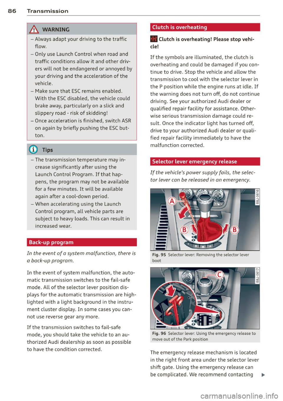
Selector lever emergency release
If the vehicle's power supply fails, the selec
tor lever can be released in an emergency.
--
-
-
-
-
---Fig. 95 Selecto r lev er: Remov ing the selector le ver
boot
Fig. 96 Selecto r lever : Using the emerge ncy release to
move out of the Park positio n
The emergency release mechanism is located
i n the right front area under the selector lever
shift gate. Using the emergency release can
be complicated. We recommend contacting ..,_
Page 145 of 244
Switching ESC off (sport mod e)
I n ce rtain sit uat ions, it m ight make sense to
allow some slip. For example :
- Rocking the vehicle to free it when it is stuck
- Driving in deep snow or on loose ground
- Driving with snow cha ins
Press the[!] button . The ESC ind icator light
II turns on and Stab iliz ation p rogr am off
appears in the display. ASR deactivates com
p letely and the stabilizat ion effects from the
ESC system are lim ited .
Sw itchin g on
Press the[!] button again. The message
Sta b i
liz ation p rog ram on
appears briefly in the dis
p lay.
A WARNING
Only switch ESC sport mode on when your
driving abilities and the traffic s ituation
permit . Please note that the dr iv ing
w heels can spin and the vehicle can break
away in ESC sport mode, especia lly when
t he road is slippery.
(D Tips
If the re a re faults in the rear spo iler sys
tem or in Audi magnet ic r ide, it may not be
possible to act ivate ESC sport mode o r
normal mode may act ivate aga in a utoma t
ically.
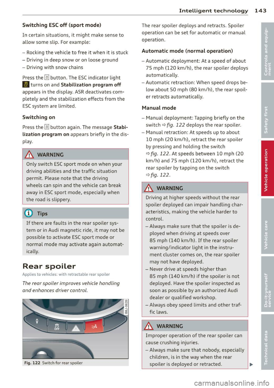
Rear spoiler
Appl ies to vehicles: with retractable rear spoiler
The rear spoiler improves vehicle handling
and enhances driver control.
Fig. 122 Switch for rear spo ile r
Intelligen t technolog y 143
The rear spoi ler deploys and retracts . Spoiler
operation can be set for automatic or man ual
operation.
Aut omatic mode (normal ope ration )
- Automatic deployment : At a speed of about
75 mph (120 km/h), the rea r spo ile r deploys
automatically .
- Au tomatic retraction: When speed drops be
low about SO mph (80 km/h), the rear spoil
er retracts a utomatica lly.
Manual mode
- Man ual deployment : T app ing br iefly on the
sw itch
¢ fig . 122 deploys the rear spoiler.
- Manual retraction : At speeds up to about
10 mph (20 km/h), retract the rear spoiler
by pressing and holding the sw itch
¢ fig. 122. At speeds between 10 mph (20
km/h) and 75 mph (120 km/h), retract the
rear spoi ler by tapping on the switch
¢ fig. 122 .
A WARNING
-
Driving at higher speeds without the rear
spoiler deployed can impair handling char
acter istics, making the vehicle harder to
control.
- Always make su re that the spo ile r is de
ployed when driving at speeds over
85 mph (140 km/h) . If th e rear spoil er
warn ing/ indicator light in the inst ru
men t cluster comes on, the rear spoiler
may not have deployed.
- Never d rive a t speeds higher than
85 mph (140 km/h) i f th e spoiler is not
deployed . Have the spoiler inspected as
soon as possible by an authorized Audi
dea ler or qualified workshop.
- A lways obey speed limits and other traf
fic laws .
A WARNING
Improper operation of the rear spoi ler can
cause crushing injuries .
- Always make sure that nobody, especially
children, is in the way when the rear
spoiler is dep loyed or retracted.
Page 149 of 244
Basically, energy management consists of
batter y di agno sis, idling cur rent man age
ment
and d yn ami c en ergy m anagement.
Battery diagnosis
Battery d iagnosis continuously dete rmines
the state of the battery. Senso rs determ ine
battery vo ltage, battery current and battery
temperature. This determines the current
state of charge and the power of the battery.
Idling curre nt management
Idling c urrent management red uces energy
consumption while the vehicle is standing.
With the ignition switched off, it contro ls the
energy supply to the various electrica l compo
nents . Data from battery diagnosis is consid
ered.
Depending on the battery's state of charge,
individua l consumers are grad ually turned off
to prevent excess ive d ischarge of the battery
and thus mainta in start ing capability.
Dynam ic energ y manag em ent
While the vehicle is being driven, dynamic en
ergy management distributes the energy gen
erated according to the needs of the individu
a l components. It regu lates consumption, so
that more electrical energy is not being used
than is being generated and ensures an opti
mal state of charge for the battery .
(D Tips
-But even energy management cannot
negate the limits of physics. Consider
that the power and life of a battery are l imited.
- If starting ab ility is threatened, you are
i nformed by a warn ing
c!;> page 148,
Driver notification in the instrument
cluster display.
Int ellig ent technolog y 147
What you should know
The highest priority is given to maintaining
starting capability.
The battery is severely taxed in short-distance
driv ing, in city traff ic and during the cold time
of year . Abundant electrical energy is re
quired, but only a l ittle is generated .
It is also
c ritical if the engi ne is not running and electri
ca l components are turned on . In this in
stance ene rgy is be ing consumed but none is
being generated.
It i s in precise ly these situations that you will
notice ene rgy management act ive ly regu lat
ing the d istribu tion of ene rgy.
V ehicle stands for an extended period
If you do not drive your vehicle over a period
of several days or weeks , e lectr ica l compo
nents a re g radually cut back or switched off.
T his reduces energy consumption and ma in
ta ins s tart ing capability over a longer pe riod .
Take into considerat ion that when you unlock
you r vehicle, some convenience functions,
s u ch as the remo te key o r power seat adjust
ment, may not be available. The convenience
f unct ions wi ll be available again when you
turn on the ignition and start the engine.
With the engine turned off
If you listen to the radio, for examp le, w ith
the engine tu rned o ff, the battery is being dis
charged .
If starting capabi lity is jeopardized due to en
ergy consumption , a message appears in the
driver in formation d isplay.
You have to start t he engine to charge the
battery.
With the engine running
Although electrical energy is generated when
the vehicle is being driven, the battery can be come discharged . This happens mostly when
little energy is being gene rated and a great
deal consumed and the battery's state of
c h arge is not opt imal.
•
•