instrument cluster AUDI TT ROADSTER 2017 Owners Manual
[x] Cancel search | Manufacturer: AUDI, Model Year: 2017, Model line: TT ROADSTER, Model: AUDI TT ROADSTER 2017Pages: 314, PDF Size: 76.54 MB
Page 9 of 314
co
co
.... N
" N .... 0
" "' c:o
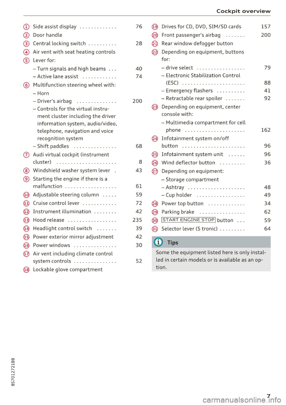
(!) Side assist display ..... ... .. .. .
@ Door handle
®
©
®
Cent ral locking switch
Air vent with seat heating controls
Lever for:
- T urn s ignals and h igh beams .. .
- Active lane assis t ......... .. .
® Multifunction steering wheel with :
- Horn
- Driver's ai rbag .. ......... .. .
- Controls for the virtual instru-
ment cluster includ ing the driver
information system, aud io/video,
telephone, navigation and voice
recogn ition system
- Shift paddles . .... ..... ... . .
0 Aud i v ir tu al co ckpit (instrument
cluster) ... .... .. .... ... .. .. .
@ W indshield washer system lever
® S tarting the engi ne if the re is a
mal func tion .. ........... .. .. .
@ Adjustab le st eering column . ... .
@ Cruise co ntrol lever .. ..... ... . .
@ Ins trument i llum ination ... .. .. .
@ Hood release . .... ......... .. .
0 H eadlight cont rol sw itch .... .. .
@ Power exterior mirror adjustment
@ Power windows . .... ..... ... . .
@ A ir ven t incl uding climate con trol
system controls ... .... ... .. .. .
@ Lockable g love compartment
76
28
40
74
200
68
8
43
6 1
59
72
42
235
39
42
30
52
Coc kpit o ve rv iew
@) Drives for CD, DVD, SI M/SD cards
@ Front passenger's ai rbag ...... .
@ Rear window defogger bu tton
@ Depending on equipment, buttons
for:
- drive select .. .. ............ .
- Electronic Stabilization Control
(ESC) ..... .. .. ............ .
- Emergency flashers . ...... .. .
- Retractab le rear spoiler ...... .
@ Depend ing on equ ipment , center
co nsole with:
- Mu ltimedia compartment for cell
phone .... .. .............. .
~ Infotai nment system on/off
button . .. .. .. .. ............ .
@ Infotainment system unit ... .. .
@ Wind deflector button ........ .
@ Depending o n eq uipment:
- Storage compartment
- Ashtray ... .. ... .. .. ..... .. .
- Cup holder .. ... .. .. ..... .. .
@ Power top button ............ .
@ Parking b rake . .. ............ .
@ I S TAR T ENGINE ST OP I butto n ...
@ Selector lever (S tronic)
@ Tips
1S7
200
79
88
41
92
162
9 6
96
36
48
49
34
62
59
64
Some the equipment listed here is only instal
l ed in certa in models or is available as an op
tion.
7
Page 10 of 314
Instrumen ts and ind icator ligh ts
Instruments and indicator Lights
Instruments
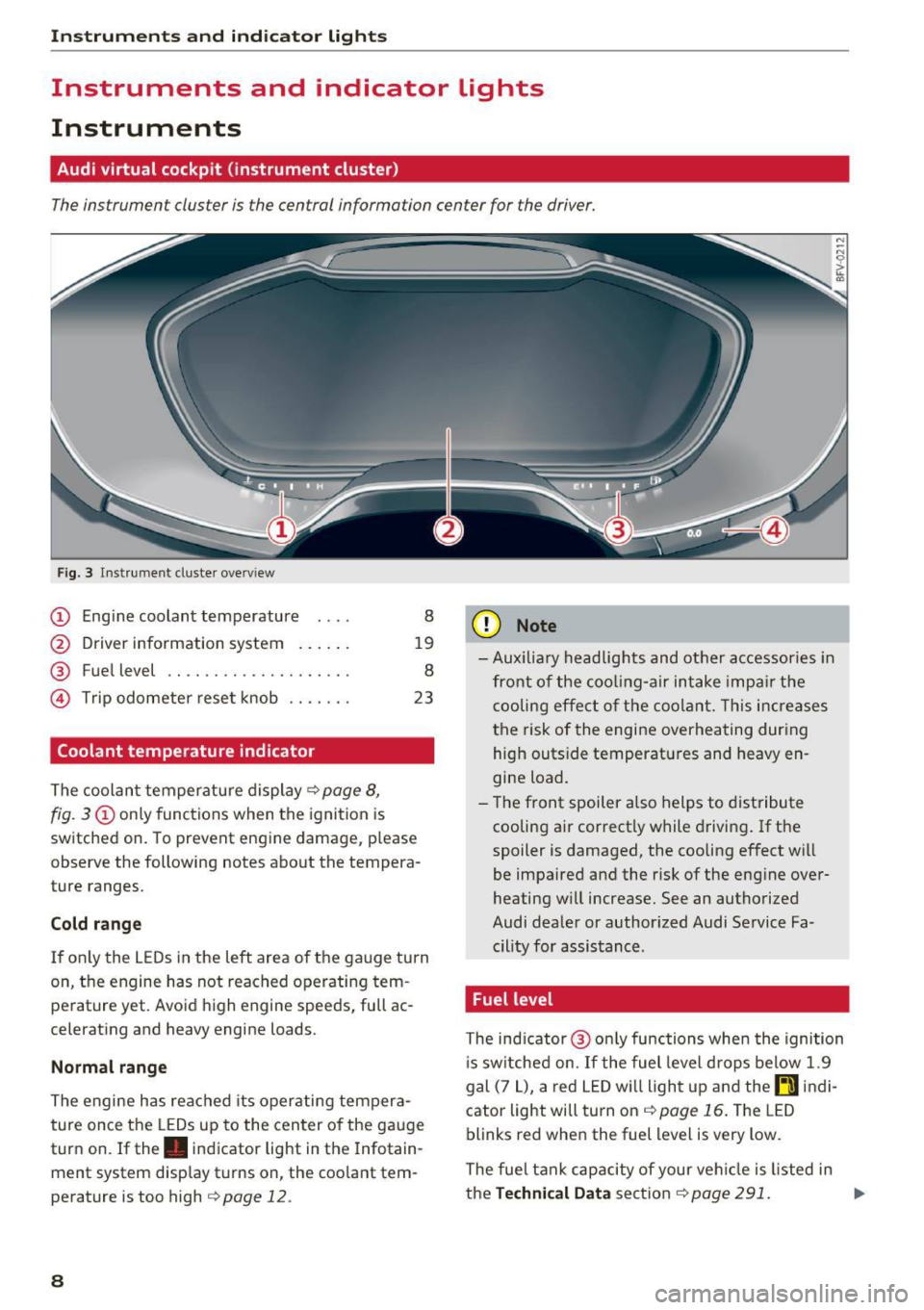
Audi virtual cockpit (instrument cluster)
The instrument cluster is the central information center for the driver.
Fig. 3 Instrume nt cluster overv iew
(D Eng ine coolant temperature 8
@ Driver information system . . . . . . 19
® Fuel level . . . . . . . . . . . . . . . . . . . . 8
@ Trip odometer reset knob . . . . . . . 23
Coolant temperature indicator
The coolan t temperature display c:> page 8,
fig. 3
(D only functions when the ignition is
switched on. To prevent engine damage, p lease
observe the following notes about the tempera
ture ranges.
Cold rang e
If o nly the L EDs in the left area of the gauge turn
on, the engine has not reached operating tem
perature yet. Avoid high engine speeds, full ac
celerating and heavy engine loads .
Normal range
The engine has reached its operating tempera
ture once the LEDs up to the center of the gauge
turn on . If the . indicator light in the Infotain
ment system display turns on, the coolant tem
perature is too high
c:> page 12.
8
(D Note
-Aux iliary head lights and other accessories in
front of the coo ling-a ir intake impa ir the
cooling effect o f the coolant. This increases
the risk of the engine overheating during high outside temperatures and heavy en
gine load.
- T he front spoiler a lso helps to distribute
cooling air correctly while driving . If the
spoiler is damaged, the cooling effect will
be impaired and the risk of the eng ine over
heating w ill increase. See an authorized
Audi dealer or author ized Audi Service Fa
cility for assistance .
Fuel level
The indicator @ only func tions when the ignition
i s sw itched on. If the fuel level drops below 1.9
gal (7
L), a red LED wi ll light up and the rD indi
cator light will turn on
c:> page 16 . The LED
blinks red when the fuel level is very low.
The fuel tank capacity of your veh icle is listed in
the
Techni cal Dat a sectio n c:> page 291. ..,_
Page 11 of 314
co
co
.... N
" N .... 0
" "' c:o
(D Note
Never drive until the tank is completely emp
ty. The irregular supply of fuel that results
from that can cause engine misfires . Uncom
busted fuel will then enter the exhaust sys
tem. This can cause overheating and damage
to the catalytic converter .
Indicator lights
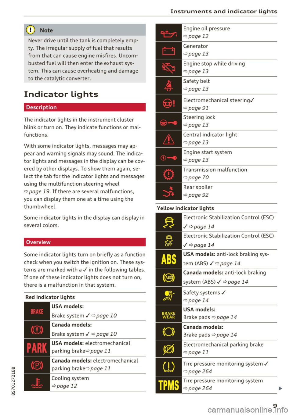
Description
The indicator lights in the instrument cluster
blink or turn on. They indicate functions or mal
functions.
With some indicator lights, messages may appear and warning signals may sound. The indica
tor lights and messages in the display can be cov
ered by other displays. To show them again, se lect the tab for the indicator lights and messages
using the multifunction steering wheel
c;, page 19. If there are several malfunct ions,
you can display them one at a time using the
thumbwheel.
Some ind icator lights in the display can display in
several colors .
Overview
Some indicator lights turn on briefly as a function
check whe n you switch the ign ition on . These sys
tems are marked with a
,I in the following tables.
If one of these indicator lights does not turn on,
there is a ma lfunction in that system.
Red indicator lights
---------------
US A models :
Brake system ./ c;, page 10
Canada models:
Brake system ./ c;, page 10
USA models : electromechanical
parking brake¢
page 11
Canada models: electromechanical
parking brake¢
page 11
Cooling system
<=>page 12
Instruments and indicator lights
Engine oil pressure
c;,page 12
Generator
¢page 13
Engine stop while driving
¢page 13
Safety be lt
c;, page 13
Electromechanical steering./
c;,page 91
Steering lock
¢page 13
Central indicator light
c;,page 13
Engine start system
c;,page 13
Transmission malfunction
c;, page 70
Rear spoiler
c;,page 92
Yellow indicator lights
Electronic Stabilization Contro l (ESC)
,I c;, page 14
Electronic Stabilization Control (ESC)
./ c;, page 14
USA models: anti-lock braking sys
tem (ABS)./
c;, page 14
Canada models: anti-lock braking
system (ABS) ./
c;, page 14
Safety systems ,I
c;,page 14
USA models:
Brake pads c;, page 14
Canada models:
Brake pads c;, page 14
Electromechanical parking brake
c;,page 11
Tire pressure monitoring system../
c>page264
Tire pressure monitoring system
<=>page 264
9
Page 15 of 314
co
co
.... N
" N .... 0
" "' c:o
@ Tips
The oil pressure warning is not an o il level in
dicator. Always check the oil level reg ularly .
D Generator/vehicle battery
• Electric system: malfunction! Battery is not
being charged
There is a malfunction in the alternator or the ve
h icle elect rical system.
Dr ive t o an autho rized Aud i dea le r o r a uth orized
Au di Service Facility immediately. Tur n off all un
necessa ry e lectr ica l equi pment because it w ill
drain the batte ry. See your authorized A udi deal
er or authori zed Audi Service Facility if the bat
tery charge level is too low .
(•) Electrical system: low battery charge. Bat
tery w ill be charged while driving
The start ing a bili ty may be impai red.
I f t his message tu rns off aft er a lit tle while , the
ve hicl e ba ttery charged enough w hile dr iving.
If the message does not turn off, have an a uthor
iz ed A udi dealer o r au tho riz ed Aud i Serv ice Fac ili
ty repa ir th e malfunction.
~ Engine stop while driving
• Engine stopped : no power steering or brake
servo possible
There is a malfunction in the eng ine o r in the fue l
supp ly sys tem .
Mo re force is needed to steer and bra ke the mov
in g vehicle when t he engine is stopped. If the ve
hi cle is roll ing , try to b ring it to a stop off to the
side from moving traffic. See an au thoriz e d Au di
dea le r or autho riz e d Au di Serv ice Fa cility fo r as
sis tance.
A WARNING
If the eng ine stops while dr iving , yo u will
nee d to use more fo rce to bra ke the vehicle .
Th is increases the r isk o f an acci dent . There
w ill st ill be power steering if the ignit ion is
switched on w hil e the vehicle is rolling and
Instruments and ind icator lights
the re is suff ic ient battery charge. Ot herwise,
you must use greater force when stee ring.
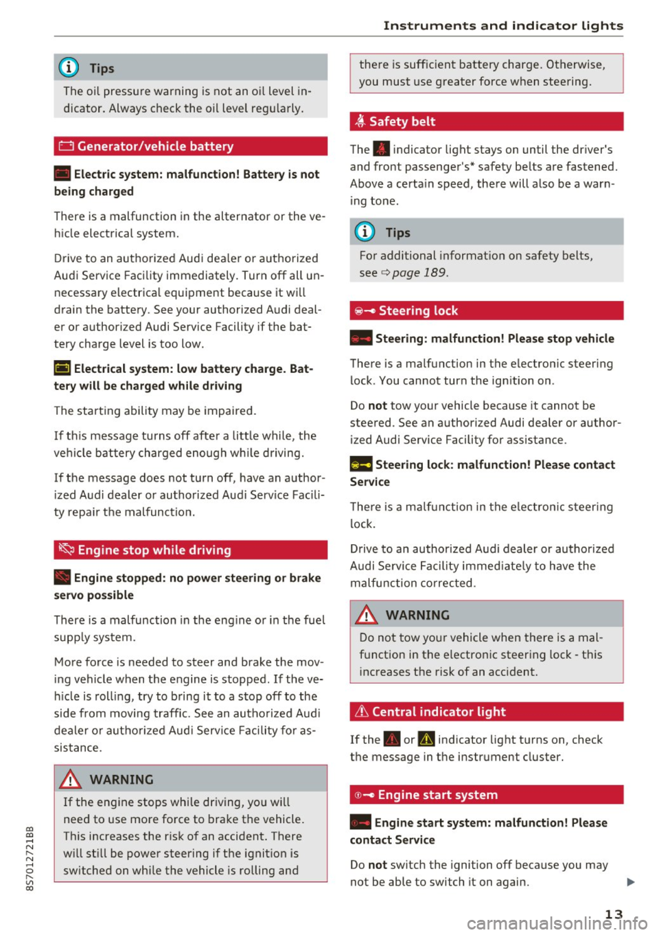
~ Safety belt
The . indicator light stays on until the dr iver's
and fro nt passenger's* safety be lts a re fastened .
Above a certa in speed, the re will a lso be a war n
i ng tone .
(D Tips
For additional informat ion on safety belts,
se e
c:> page 189 .
@-c, Steering lock
• Steering: malfunction! Please stop veh icle
The re is a ma lfunction in the e lectron ic steering
lock . You cannot tur n the ign ition on .
Do
not tow yo ur vehicle because it cannot be
stee red. See an a uthori zed Audi dea ler or author
ized Audi Service Facility for ass istance.
f!m Steering lock: malfunction! Please contact
Service
T he re is a m alfu n cti on in the e lectron ic st eering
l ock .
Dr ive to an author ized A udi dealer or au tho riz e d
A udi Se rvice Fa cility i mmed iate ly to h ave the
ma lfunction correcte d.
D o not tow yo ur vehicle when there is a mal
f u nction in t he electron ic steer ing lock -th is
i nc reases the risk of an acc iden t.
6 Central indicator light
If the . or Pm in dicator light t urns on, check
t h e message in the i nstr ument cluster.
© -c> Engine start system
• Engine start system: malfunction! Please
contact Service
Do not switch the ignition off because you may
not be able to switch it on again.
Ill>-
13
Page 19 of 314
CD
CD
.... N
" N .... 0 r--. V, co
@:.D Light/rain sensor
l!I Automatic headlights: malfunction! See
owner' s manual
El Automatic wipers : malfun ction! See owner 's
manual
The light/ra in sensor is malf unct ion ing.
The low beams remain switched on at all times
for safety reasons when the light switch is in the
AUTO position. You can continue to turn the
lights on and off using the light switch . You can
still cont rol a ll wipe r functions that a re inde
pendent of the ra in se nsor.
Drive to an authorized Aud i dea ler or a ut horized
Audi Service Facility immediately to have t he
malfunction corrected .
; Adaptive dampers
Applies to: vehicles with Audi drive select
B Suspension : malfunction! You may continue
driving
There is an adaptive damper malf unct ion.
Drive to an aut horize d Aud i dea le r or a uthorized
Aud i Service Facility immediately to have t he
malfunct ion corrected.
¢i ¢ Turn signals
If t he B or Ill indicator light b links, a t urn sig
n a l is turned on. If both indicator lig hts are blink
i ng, the eme rgency flash ers a re on .
On-Board Diagnostic
system (OBD)
Malfunction indicator lamp (MIL)
The malfunction indica to r l amp (MIL) ¢.j in the
in str ument cluster is part of the O n Board Diag
n os tic Sys tem ( OBD II).
The warning/indicator light turns on w hen the ig
ni tion is switched o n and turns off once the e n
g ine is s tarted an d is runn ing in id le at a stab le
speed. This indica tes th at the MIL is functioning
cor re ct ly.
Instruments and indicator lights
If the light does not turn off after starting the
engine
or turns on while driving, this may in di
cate there is a malfunction in the engine.
If the
indicato r turns on, the cata lytic conve rter may be
damaged .
Drive
with reduced engine performan ce (avo id
high speeds for extended per io d s of t ime and/o r
fast acceleration) and have the ma lfunction cor
rected. See an author ized Audi dealer or author
ized Audi Service Facility.
The in dicator may turn on if the e lectron ic speed
li miter is faulty. For add it iona l information, see
¢ page 72, Electronic speed limiter.
On-Board Diagnostics
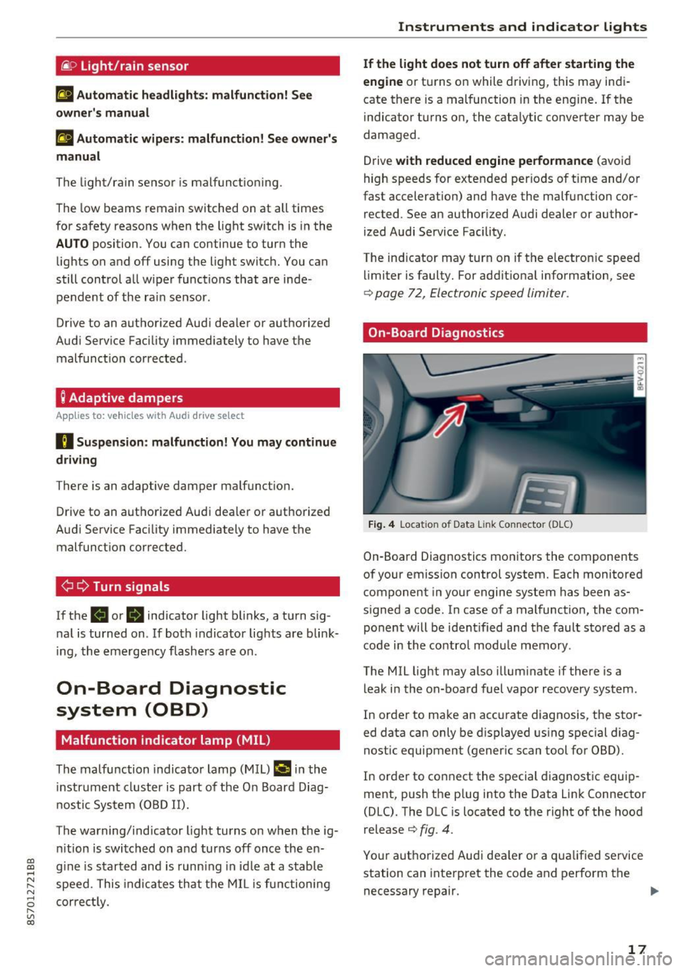
Fig. 4 Location of Data Link Connector (DLC)
On-Boa rd Diagnostics mo nitors the components
of your emission control system. Each monitored
component in your engine system has been as
s igned a code. In case o f a malfunction, the com
ponent will be i dent ified and the faul t st o red as a
co de i n t he co ntro l mo dule mem ory.
The MIL lig ht may also illum inate if there is a
leak in the on-boa rd fuel vapor recovery system .
In or de r to ma ke an acc urate diagnosis, the sto r
ed data can only be d isplayed using special d iag
nostic equipment (gener ic scan to ol for OBD).
In order to co nnect the s pecial diagnost ic equi p
ment, push the p lug into the Data Link Connector
(DLC). T he DLC is located to the right of the hood
re lease
¢ fig. 4.
You r aut horize d Aud i dea le r or a qua lified se rvice
station can inte rpret the code and perform the
necessary repair.
IJJI,
17
Page 36 of 314
Power top
Power top
Power top
General information
The power top opens and closes automatically .
When open, the power top is stored completely
in the power top compartment. The power top
can be opened or closed at speeds up to 30 mph
(SO km/h).
Under normal conditions, the power top is wind
and waterproof. In rare cases, small droplets of
water may form under extreme weather condi
tions such as torrential or prolonged rain. That is
normal and no cause for concern.
Follow the care instructions to keep the power
top free of leaks and to maintain its appearance
~ page 266, Core and cleaning. Also observe the
following:
- Open and stow the power top only when it is
clean and dry . Sharp-edged dirt particles can
cause damage to the rear window and the pow
er top . Stowing the power top when it is damp
can create imprints in it, and if it is left that
way for long periods of time, mildew and other
damage can form .
- Do not leave the power top open for several weeks or the creases in it may become discol
ored.
- Remove ice and snow before opening the power
top. Do not use any sharp edged objects to re move ice and snow or the power top could be
scratched or damaged . The rear window may be
cleared with a standard ice scraper .
- Do not open the power top when the tempera
ture is below 32 °F (0 °C). The fabric in the
power top loses elasticity in sub-zero tempera
tu res .
34
Opening and closing the power top
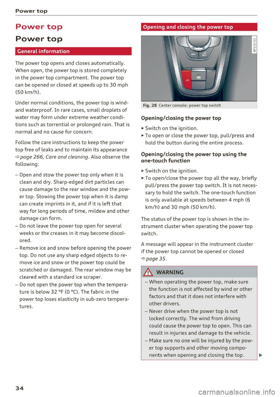
Fig. 28 Center conso le: power top sw itch
Opening/closing the power top
.,. Switch on the ignition.
.,. To open or close the power top, pull/press and
hold the button during the entire process.
Opening/closing the power top using the
one-touch function
.,. Switch on the ignition .
.,. To open/close the power top all the way, briefly
pull/press the power top switch. It is not neces
sary to hold the switch. The one-touch function
is only available at speeds between 4 mph (6
km/h) and 30 mph (SO km/h).
The status of the power top is shown in the in
strument cluster when operating the power top
switch.
A message will appear in the instrument cluster
if the power top cannot be opened or closed
~ page 35.
A WARNING
-When operating the power top, make sure
the function is not affected by wind or other
factors and that it does not interfere with
other drivers.
- Never drive when the power top is not
locked correctly. The wind from driving
could cause the power top to open. This can
result in injuries and damage to the vehicle .
- Make sure no one will be injured by the pow
er top supports and other moving compo
nents when opening and closing the top.
Page 37 of 314
CD
CD
.... N
" N ...... 0 r--. V, co
-When operating the power top, visibility to
the rear is limited. Avoid operating the top
while driving in reverse.
(D Note
-To prevent damage to the power top:
- do not store any objects in the power top
storage compartment .
- make sure there is enough space above
the vehicle when opening or closing the
power top.
(D Tips
- To prevent the vehicle battery from draining
unnecessarily, do not open or close the pow
er top repeatedly when the engine is switch
ed off.
- A message will appear in the instrument cluster if there is a malfunction in the power
top
¢ page 35.
- The power top can also be operated manual
l y temporarily if there is a malfunction
¢ page 3 7, Power top emergency opera
tion.
An authori zed A udi dealer or au thor
i zed Audi Service Facility should diag nose
and correct the cause of the ma lfunction as
soon as possib le .
- If the vehicle is parked with the power top open, the vehicle interior is not p rotected
from damaging weather or unauthorized ac
cess. Lock any items you leave behind in the
l uggage compartment. Close the power top
before leaving the vehicle .
- The side windows automat ically lower
slight ly when opening or closing the power
top.
P owe r top
Power top convenience opening and closing
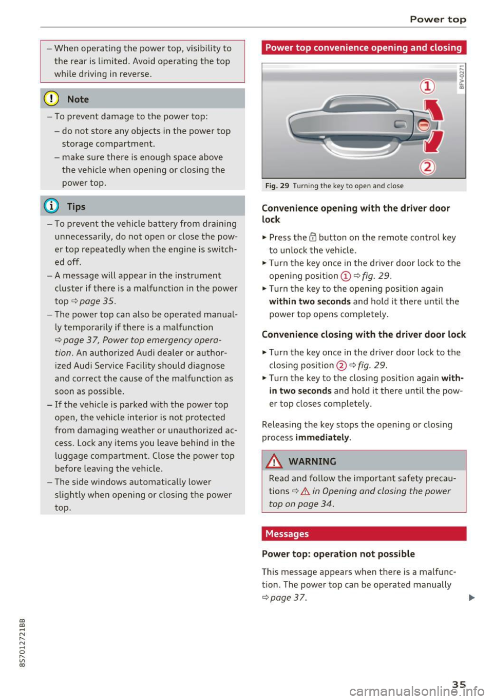
Fig. 29 Turning the key to open and close
Conven ience opening with the dri ver door
lock
.,. Press the 63 button on the remote control key
to un lock the vehicle .
.,. Turn the key once in the driver door lock to the
open ing pos ition
© ¢fig. 29.
.,. Turn the key to the opening posi tion again
within tw o second s and hold it there until the
power top opens completely.
Convenience closing with the driver door lock
.,. Turn the key once in the driver door lock to the
clos ing position @¢
fig. 29.
.,. Tur n the key to the closing position again
with
in two second s
and ho ld it there un til the pow
er top closes complete ly .
Releasing the key s tops the opening or clos ing
process
immedi ate ly.
A WARNING
-
Read and fo llow the important safety preca u
tions
¢ .&. in Opening and closing the power
top on page 34.
Messages
Pow er top : operation n ot pos sibl e
This message appears when there is a malfunc
t ion. The power top can be operated manually
¢ page 37. ..,.
35
Page 44 of 314
Lights and Vision
Instrument illumination
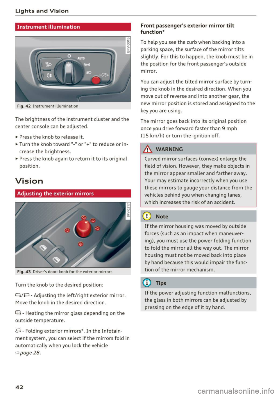
Fig . 42 Inst ru m ent illuminat io n
"' ~ 0 0
~ (0
The brightness of the instrument cluster and the
center console can be adjusted.
• Press the knob to release it .
• Turn the knob toward"-" or"+" to reduce or in
c rease the b rightness .
• Press the knob again to ret urn it to its original
pos ition.
Vision
Adjusting the exterior mirrors
F ig. 4 3 Driver's door: knob for the exter ior m irrors
T u rn the knob to the desired pos ition:
Q/P -Adjusti ng the left/right exter ior mir ror.
Move the knob in the desired direction.
®-Heat ing the mi rror g lass depending on the
outside temperat ure.
8 -Folding exterior mirrors *. In the Infotain
ment system, you can select if the mirrors fold in
automatically when you lock the vehicle
9 page28.
42
Front passenge r's exterior mirror tilt
function *
To help you see the cur b when backing into a
parking space, the surface of the m irror tilts
slight ly. For this to happen, the knob must be in
the position for the front passenger's outside
mir ror .
You can adjust the tilted mirror s urface by turn
i ng the knob in the desired direct ion. When you
move out of reverse and into another gear, the
new m irror position is stored and assigned to the
key you are using.
The m irror goes back into its or ig inal pos ition
once you drive forward faster than 9 mp h
(15 km/h) or turn the ignition off .
,&. WARNING
Curved mirror surfaces (convex) e nla rge the
field of vision. Howeve r, they make objec ts in
the m irror appear s maller and fart he r aw ay.
Your may estima te inc orrec tly when yo u use
these m irrors to ga uge you r distan ce from the
vehicles behind you w hen changing la nes ,
which increases the risk of an accident.
(D Note
If th e mir ror h ousing w as move d by o utsid e
forces (such as an imp act when ma neuver
i ng), you must use the power fo lding funct ion
to fo ld the m irror all the way out. The m irror
h ousing must not be moved back into place
by hand because this would impair the func
tion o f the m irro r mechan ism.
(D Tips
If the power ad justing function ma lfunctions ,
the glass in both m irrors can be adjusted by
pressing on t he edge of it by hand.
-
Page 64 of 314
Driving
Electromechanical
parking brake
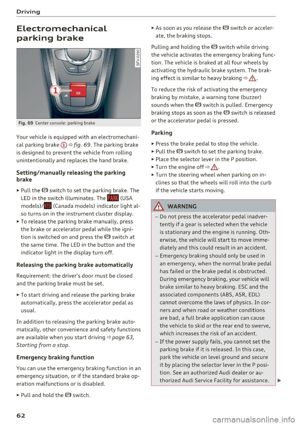
Fig . 69 Center conso le: par king brake
Your vehicle is equipped with an electromechani
cal parking brake
(D o fig. 69. The parking brake
is designed to prevent the vehicle from rolling
unintentionally and replaces the hand brake.
Setting /manuall y re le asing the parking
bra ke
.. Pull the(®) switch to set the parking brake. The
LED in the switch illuminates. The -(USA
models)/ . (Canada models) indicator light al
so turns on in the instrument cluster display .
.. To release the parking brake manua lly, press
the brake o r acce lerato r pedal while the igni
tion is swi tched on a nd p ress the
«el) switch at
the same time. The L ED in the b utton and the
indicator light in the display t urn off.
Releasing the parking brake automatically
Req uirement: the driver's door must be closed
and the park ing brake must be set.
.. To start driving and release the park ing brake
automat ically, press the accelerator pedal as
u su al.
In addition to releasing the park ing brake auto
mat ica lly, other convenience and safety functions
are available when you start driving
o page 63,
Starting from a stop .
Emergency braking function
You can use the emergency brak ing function in an
emergency situation, or if the standard brake op
eration mal functions or is disabled .
.. Pull and hold th e®> switch.
62
.. As soon as you re lease the (®) switch or acceler-
ate, the braking stops.
P ulli ng and ho ld ing the®) switch wh ile driving
the ve hicle ac tiva tes the emerge ncy braking func
tion . The vehi cle is braked at a ll four wheels by
activating the hydraulic brake system . The brak
i ng effect is sim ilar to heavy brak ing
o ,A .
To reduce the risk of act ivat ing the emergency
braking by mistake, a warning tone (buzzer)
sou nds when the© switch is pulled . Emergency
bra king stops as soon as the®) switch is released
or the accelerator pedal is pressed.
Parking
.. Press the bra ke pedal to stop the veh icle.
.. Pull the®> switch to set the parking brake.
.. Place the selector lever in t he P position .
.. Turn the engine off
cc> ,A.
.. Turn the steering wheel when parking on in
cl ines so that the wheels w ill roll into the curb
if the vehicle starts moving.
.&. WARNING
- Do not press the acce lera to r pedal inadve r
tently if a gea r is selec ted whe n the vehicle
is st ation ary and the e ngine is runni ng. Oth
erwise, the vehi cle will s tart to move imme
diate ly and this could result i n an accident.
- E mergency brak ing sho uld only be used i n
an emergency, when the norma l bra ke pe dal
has failed or the brake peda l is o bstr ucted .
During emergency brak ing, your vehicle will
brake s imilar to heavy braking. ESC and the
associated components (ABS, ASR, EDL)
cannot ove rcome the laws of physics. In co r
ners and when road or weather conditions
are bad, a fu ll brake application can cause
the vehicle to s kid or the rea r end to swe rve,
whi ch in crease s the risk of an ac cident.
- I f the power supply fails, you cannot set the
pa rking bra ke if it is released. In this ca se,
p ar k the vehicle on leve l grou nd and secure
it by plac ing the sele ctor lever in the P pos i
tion. See an authorized A udi dealer or au -
thorized A udi Service Facil ity for assistance.
~
Page 74 of 314
Ass is t
Assist
Electronic speed Limiter
Your v ehicle may be factory equipped with tires
that are rated for a maximum speed of 130 mph (210 km/h). This is less than the maximum sp eed
of your vehicle . To reduce the risk of sudden tire
failure and loss of control if the vehicle is operat ed at excessive speeds, your vehicle also has an
electronic speed limiter . The electronic speed
lim iter prevents your vehicle from going faster
than the t ire speed rating. For mo re information
~ page 253.
If the engine control unit receives faulty vehicle
road speed s ignals , the Malfunction Indicator
L amp (MIL)
¢..ffi will illumina te . If this occurs,
con tact the nearest au thorized A ud i dealer for
assistance.
_& WARNING
Always observe the posted speed limits and
adjust you r speed to suit prevailing road, traf
fic and weather conditions. Never drive your
vehicle faster than the maximum speed rating
of the tires installed .
Speed warning system
Applies to: vehicles with speed warning system
The speed warning system helps you to stay be
low a specified maximum speed that can be set,
changed or deleted in the Infotainment system . -
The speed warning system warns you if you are
exceeding the maximum speed that you have set
.
A warni ng tone will sound as soon as you r speed
exceeds the sto red value s lightly . The
(OJ (USA
models)
I [OJ (Canada models) indicator light
and a message appear i n the ins trumen t cluster
d isp lay a t the same time. Th@
Hll (USA models)/
[O](Canada models) i ndicator light and the mes
sage turn off when the vehicle speed drops be low
the stored maximum speed.
Se tting a threshold is rec om mended if you would
like to be reminded when yo u reach a certa in
maximum speed . Situations where you may want
to do so include driving in a country w it h a ge ne r-
72
al speed limit or if there is a spec ified maximum
speed for winter tires.
Setting the warning threshold
.,. Select in the Infotainment system: IM ENU ! but
t on
> Vehicle > left con trol b utton > Driver as
sistance > Speed warning > Manu al.
a) Tips
Regar dless of the speed warning sys tem, you
sh ould alw ays mon itor your spee d using the
speedometer and tnake s ure yo u are fo llow ing
the lega l speed limit.
Cruise control system
Switching on
Applies to: vehicles with cruise control system
The cruise control sys tem makes it possible to
drive at a constant speed starting at 15 mph (20kmlh) .
0
f
~
0
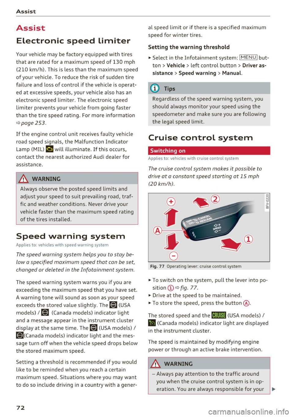
Fig. 7 7 Operat ing lever: c ruise co ntro l sy ste m
.,. To switch on the system, pu ll the lever in to po -
sition @~
fig. 77 .
.,. Drive at th e speed to be maintained.
.,. To store the speed, press the button @.
The stored speed and the
M;\1)~1j (USA models) /
l'I (Canada models) indicator light are disp layed
in the instrument cluster.
The speed is maintained by modifying engine power or through a n active brake intervention.
_& WARNING
- Always pay attention to the traffic around
you when the cruise contro l system is in op
erat ion. You are always respons ible for your ,...