AUDI TT ROADSTER 2019 Owners Manual
Manufacturer: AUDI, Model Year: 2019, Model line: TT ROADSTER, Model: AUDI TT ROADSTER 2019Pages: 304, PDF Size: 80.77 MB
Page 271 of 304
8S8012721BA
Emergency assistance
— The tire sealant must not come in contact
with skin, eyes, or clothing.
— If tire sealant comes into contact with your
eyes or your skin, thoroughly rinse the af-
fected area immediately with clean water.
— Do not inhale the fumes.
— If you swallow any of the tire sealant, thor-
oughly rinse your mouth immediately and
drink a lot of water. Do not induce vomiting.
Seek medical attention immediately.
— Change your clothing immediately if it
comes into contact with tire sealant.
— If an allergic reaction occurs, seek medical
attention immediately.
— Keep the tire sealant away from children.
G) Tips
— If sealant leaks, allow it to dry in place. You
can then peel it off like a sticker.
— Note the expiration date on the sealant bot-
tle. Replace the tire sealant at an authorized
Audi dealer or authorized Audi Service Fa-
cility.
— Radio reception can be interrupted when
operating the compressor.
— Follow the legal regulations that are appli-
cable in the country where you are operating
the vehicle.
Fate ma cry
Applies to: vehicles with tire mobility kit
RAZ-0213]
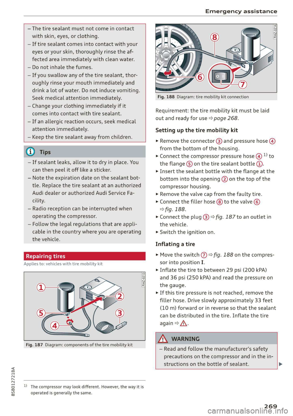
Fig. 187 Diagram: components of the tire mobility kit
D_ The compressor may look different. However, the way it is
operated is generally the same.
mo FP
aa Z, (Fy
Fig. 188 Diagram: tire mobility kit connection
Requirement: the tire mobility kit must be laid
out and ready for use > page 268.
Setting up the tire mobility kit
» Remove the connector @) and pressure hose (4)
from the bottom of the housing.
> Connect the compressor pressure hose (4) ) to
the flange ©) on the tire sealant bottle @.
> Insert the sealant bottle with the flange at the
bottom into the opening (2) on the top of the
compressor housing.
> Remove the valve cap from the faulty tire.
> Connect the filler hose (8) to the valve ©)
> fig. 188.
> Connect the plug @) > fig. 187 to an outlet in
the vehicle.
> Switch the ignition on.
Inflating a tire
> Move the switch (7) > fig. 188 on the compres-
sor into position I.
> Inflate the tire to between 29 psi (200 kPA)
and 36 psi (250 kPA) and read the pressure on
the gauge.
> If this tire pressure is not reached, remove the
filler hose. Drive slowly approximately 33 feet
(10 m) forward or in reverse so that the sealant
can be distributed in the tire. Inflate the tire
again > A\.
ZA WARNING
— Read and follow the manufacturer's safety
precautions on the compressor and in the in-
structions on the bottle of sealant. >
269
Page 272 of 304
Emergency assistance
— Ifa tire pressure of 29 psi (200 kPA) cannot
reached after inflating for 6 minutes, then
the tire is too severely damaged. Do not con-
tinue driving.
— If the tire cannot be repaired with the tire
sealant, see an authorized Audi dealer or au-
thorized Audi Service Facility for assistance.
@) Tips
Do not operate the compressor for more than
six minutes continuously, or it can overheat.
Once the compressor has cooled, you can con-
tinue to use it.
fey CLL)
Applies to: vehicles with tire mobility kit
> Affix the sticker that says "max. 50 mph (max.
80 km/h)" that is provided with the tire mobili-
ty kit within the driver's field of vision.
> Stop the vehicle after driving for about 10 mi-
nutes and check the tire pressure.
> If the tire pressure is lower than 19 psi (130
kPA), then the tire is too severely damaged. Do
not continue driving.
ZA WARNING
Pay attention to the following after repairing
the tire:
— Do not drive faster than 50 mph (80 km/h).
— Avoid hard acceleration or braking and driv-
ing fast around curves.
— The vehicle may become more difficult to
control.
— If the tire is too severely damaged, see an
authorized Audi dealer or authorized Audi
Service Facility for assistance.
@ For the sake of the environment
You can give the used tire sealant bottle to an
authorized Audi dealer or authorized Audi
Service Facility for disposal.
@ Tips
Remember to obtain a new bottle of sealant
from an authorized Audi dealer or authorized
Audi Service Facility after repairing a tire.
270
Replacing wheels
You must complete the preparation before
changing a tire.
> Read and follow the important safety precau-
tions > page 268, General information.
> Set the parking brake.
> Select the "P" selector lever position.
> Lay out the vehicle tool kit > page 268 and the
spare tire > page 274.
ZA WARNING
When using the vehicle jack* on a road with a
steep hill or when offroad, you must take ex-
tra precautions to prevent the vehicle from
rolling. Use suitable objects to block the front
and back of the wheel that is diagonal from
the wheel with the flat tire.
Removing the cover
B4L-1521
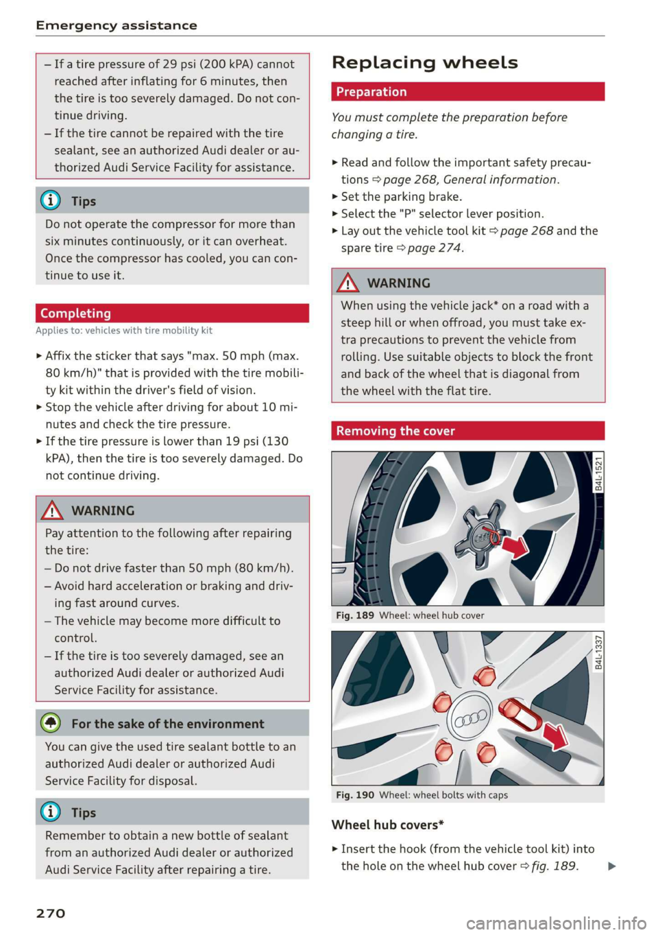
Fig. 189 Wheel: wheel hub cover
V6
Es
al
Fig. 190 Wheel: wheel bolts with caps
B4L-1337
@
Wheel hub covers*
> Insert the hook (from the vehicle tool kit) into
the hole on the wheel hub cover > fig. 189. >
Page 273 of 304
8S8012721BA
Emergency assistance
> Remove the wheel hub cover.
Wheel bolts with caps*
> Slide the plastic clip from the vehicle tool kit
onto the cap until it engages > fig. 190.
> Remove the cap with the plastic clip.
Oe ULE At ee)
Applies to: vehicles with anti-theft wheel bolts
7
i ue
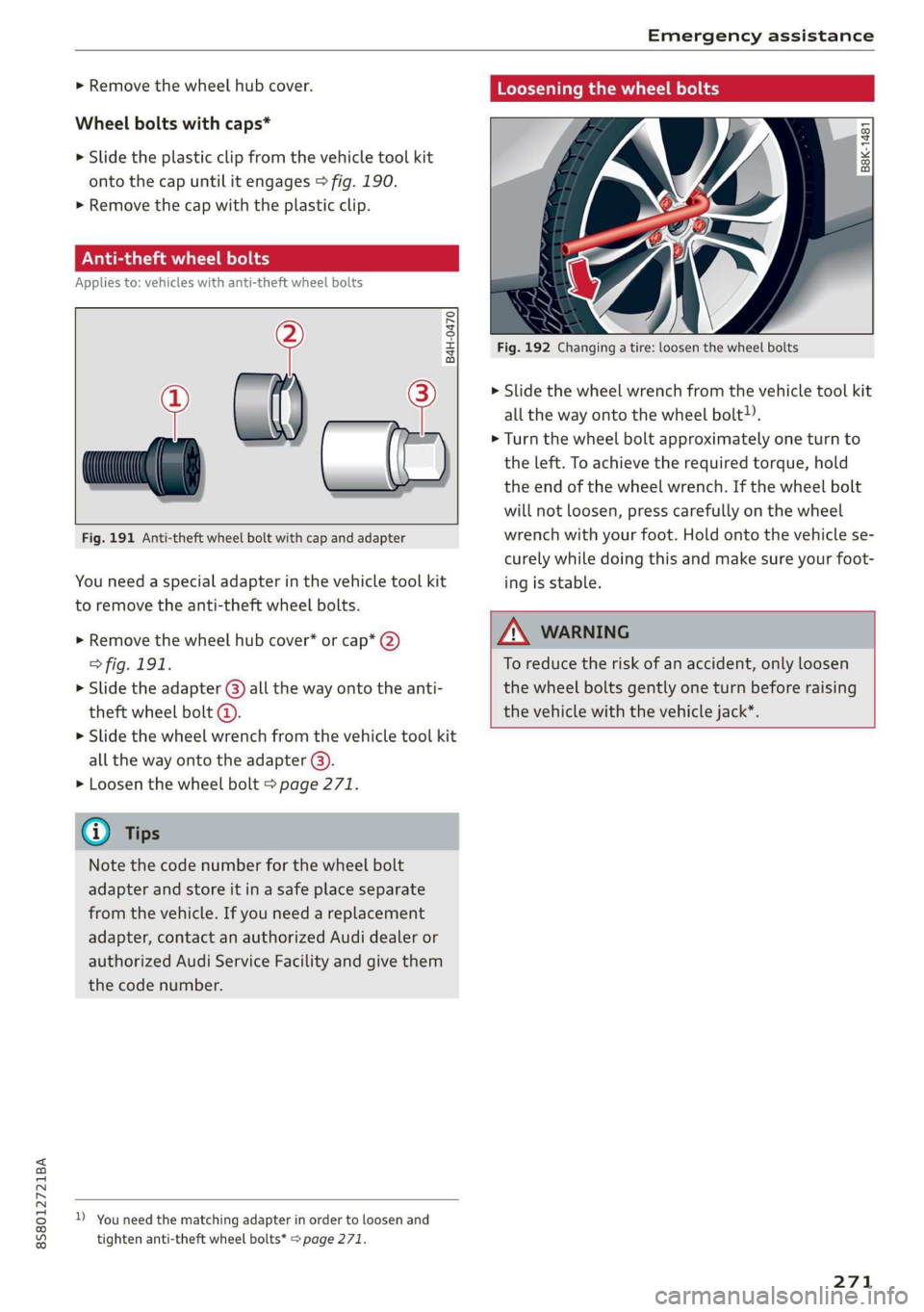
Fig. 191 Anti-theft wheel bolt with cap and adapter
B4H-0470
You need a special adapter in the vehicle tool kit
to remove the anti-theft wheel bolts.
>» Remove the wheel hub cover* or cap* 2)
> fig. 191.
> Slide the adapter () all the way onto the anti-
theft wheel bolt @.
» Slide the wheel wrench from the vehicle tool kit
all the way onto the adapter @).
> Loosen the wheel bolt > page 271.
@) Tips
Note the code number for the wheel bolt
adapter and store it in a safe place separate
from the vehicle. If you need a replacement
adapter, contact an authorized Audi dealer or
authorized Audi Service Facility and give them
the code number.
D_ You need the matching adapter in order to loosen and
tighten anti-theft wheel bolts* > page 271.
Loosening the wheel bolts
| B8K-1481
Fig. 192 Changing a tire: loosen the wheel bolts
> Slide the wheel wrench from the vehicle tool kit
all the way onto the wheel bolt).
> Turn the wheel bolt approximately one turn to
the left. To achieve the required torque, hold
the end of the wheel wrench. If the wheel bolt
will not loosen, press carefully on the wheel
wrench with your foot. Hold onto the vehicle se-
curely while doing this and make sure your foot-
ing is stable.
ZA WARNING
To reduce the risk of an accident, only loosen
the wheel bolts gently one turn before raising
the vehicle with the vehicle jack*.
271
Page 274 of 304
Emergency assistance
Raising the vehicle
Applies to: vehicles with vehicle jack
A,
BFV-0151
ry oS
a
S| > in oO
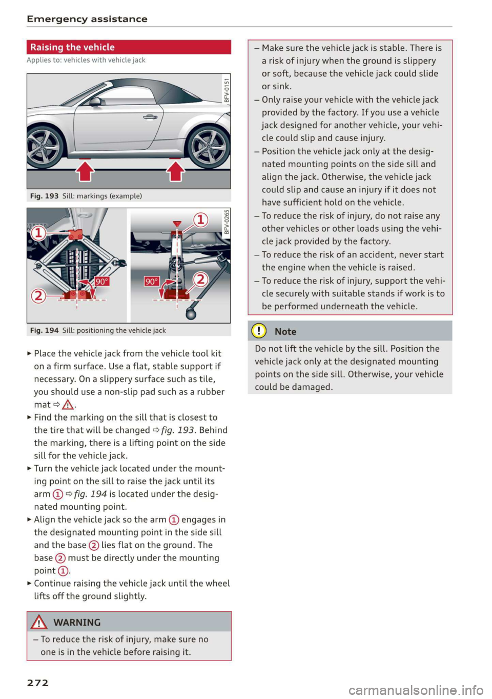
Fig. 194 Sill: positioning the vehicle jack
> Place the vehicle jack from the vehicle tool kit
ona firm surface. Use a flat, stable support if
necessary. On a slippery surface such as tile,
you should use a non-slip pad such as a rubber
mat > /\.
> Find the marking on the sill that is closest to
the tire that will be changed > fig. 193. Behind
the marking, there is a lifting point on the side
sill for the vehicle jack.
> Turn the vehicle jack located under the mount-
ing point on the sill to raise the jack until its
arm @) ° fig. 194 is located under the desig-
nated mounting point.
> Align the vehicle jack so the arm (@) engages in
the designated mounting point in the side sill
and the base (2) lies flat on the ground. The
base (2) must be directly under the mounting
point @).
> Continue raising the vehicle jack until the wheel
lifts off the ground slightly.
— Make sure the vehicle jack is stable. There is
a risk of injury when the ground is slippery
or soft, because the vehicle jack could slide
or sink.
— Only raise your vehicle with the vehicle jack
provided by the factory. If you use a vehicle
jack designed for another vehicle, your vehi-
cle could slip and cause injury.
— Position the vehicle jack only at the desig-
nated mounting points on the side sill and
align the jack. Otherwise, the vehicle jack
could slip and cause an injury if it does not
have sufficient hold on the vehicle.
—To reduce the risk of injury, do not raise any
other vehicles or other loads using the vehi-
cle jack provided by the factory.
—To reduce the risk of an accident, never start
the engine when the vehicle is raised.
—To reduce the risk of injury, support the vehi-
cle securely with suitable stands if work is to
be performed underneath the vehicle.
Z\ WARNING
—To reduce the risk of injury, make sure no
one is in the vehicle before raising it.
272
@) Note
Do not lift the vehicle by the sill. Position the
vehicle jack only at the designated mounting
points on the side sill. Otherwise, your vehicle
could be damaged.
Page 275 of 304
8S58012721BA
Emergency assistance
Removing and mounting a wheel
@ Rg Tt
“ 0 oO
B8K-1477
Fig. 196 Wheel: alignment pin in the top hole
Removing a wheel
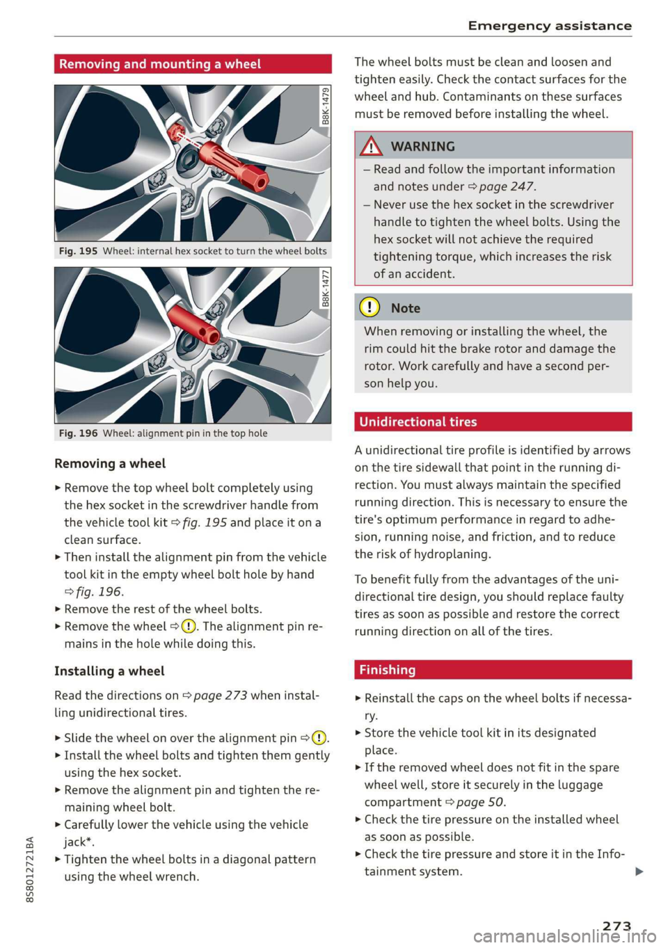
> Remove the top wheel bolt completely using
the hex socket in the screwdriver handle from
the vehicle tool kit > fig. 195 and place it ona
clean surface.
> Then install the alignment pin from the vehicle
tool kit in the empty wheel bolt hole by hand
> fig. 196.
> Remove the rest of the wheel bolts.
>» Remove the wheel >). The alignment pin re-
mains in the hole while doing this.
Installing a wheel
Read the directions on > page 273 when instal-
ling unidirectional tires.
> Slide the wheel on over the alignment pin >@.
> Install the wheel bolts and tighten them gently
using the hex socket.
> Remove the alignment pin and tighten the re-
maining wheel bolt.
> Carefully lower the vehicle using the vehicle
jack*.
> Tighten the wheel bolts in a diagonal pattern
using the wheel wrench.
The wheel bolts must be clean and loosen and
tighten easily. Check the contact surfaces for the
wheel and hub. Contaminants on these surfaces
must be removed before installing the wheel.
ZA\ WARNING
— Read and follow the important information
and notes under > page 247.
— Never use the hex socket in the screwdriver
handle to tighten the wheel bolts. Using the
hex socket will not achieve the required
tightening torque, which increases the risk
of an accident.
() Note
When removing or installing the wheel, the
rim could hit the brake rotor and damage the
rotor. Work carefully and have a second per-
son help you.
Unidirectional tires
A unidirectional tire profile is identified by arrows
on the tire sidewall that point in the running di-
rection. You must always maintain the specified
running direction. This is necessary to ensure the
tire's optimum performance in regard to adhe-
sion, running noise, and friction, and to reduce
the risk of hydroplaning.
To benefit fully from the advantages of the uni-
directional tire design, you should replace faulty
tires as soon as possible and restore the correct
running direction on all of the tires.
> Reinstall the caps on the wheel bolts if necessa-
ry.
> Store the vehicle tool kit in its designated
place.
> If the removed wheel does not fit in the spare
wheel well, store it securely in the luggage
compartment > page 50.
> Check the tire pressure on the installed wheel
as soon as possible.
> Check the tire pressure and store it in the Info-
tainment system. >
273
Page 276 of 304
Emergency assistance
> The wheel bolt tightening specification must be
90 ft lbs (120 Nm). Have it checked as soon as
possible with a torque wrench. Drive carefully
until then.
> Have the faulty wheel replaced as quickly as
possible.
Spare tire
General information
Applies to: vehicles with space-saving spare tire (compact
spare tire)
—maa
BFV-0166
The spare tire is intended for short-term use only.
Have the damaged tire checked and replaced if
necessary by an authorized Audi dealer or author-
ized Audi Service Facility as soon as possible.
There are some restrictions on the use of the
compact spare tire. The compact spare tire has
been designed specifically for your type of vehi-
cle. Do not replace it with the spare tire from an-
other type of vehicle.
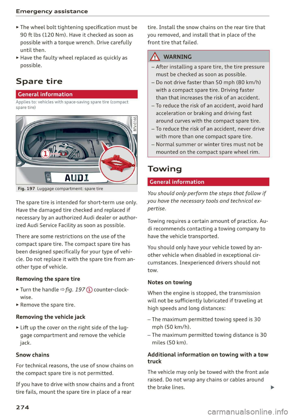
Removing the spare tire
> Turn the handle > fig. 197 @ counter-clock-
wise.
>» Remove the spare tire.
Removing the vehicle jack
> Lift up the cover on the right side of the lug-
gage compartment and remove the vehicle
jack.
Snow chains
For technical reasons, the use of snow chains on
the
compact spare tire is not permitted.
If you have to drive with snow chains and a front
tire fails, mount the spare tire in place of a rear
274
tire. Install the snow chains on the rear tire that
you removed, and install that in place of the
front tire that failed.
Z\ WARNING
— After installing a spare tire, the tire pressure
must be checked as soon as possible.
— Do not drive faster than SO mph (80 km/h)
with a compact spare tire. Driving faster
than that increases the risk of an accident.
— To reduce the risk of an accident, avoid hard
acceleration or braking and driving fast
around curves with the compact spare tire.
— To reduce the risk of an accident, never drive
with more than one compact spare tire.
— Normal summer or winter tires must not be
mounted on the compact spare wheel rim.
Towing
General information
You should only perform the steps that follow if
you have the necessary tools and technical ex-
pertise.
Towing requires a certain amount of practice. Au-
di recommends contacting a towing company to
have the vehicle transported.
You should only have your vehicle towed by an-
other vehicle when disabled in exceptional cir-
cumstances. Inexperienced drivers should not
tow.
Notes on towing
When the engine is stopped, the transmission
will not be sufficiently lubricated if traveling at
high speeds and long distances:
— The maximum permitted towing speed is 30
mph (50 km/h).
— The maximum permitted towing distance is 30
miles (50 km).
Additional information on towing with a tow
truck
The vehicle may only be towed with the front axle
raised. Do not wrap any chains or cables around
the brake lines.
Page 277 of 304
8S8012721BA
Emergency assistance
If the vehicle should be towed with the axle
raised, then the ignition must be switched off to
reduce the risk of damage to the drivetrain.
Tow bar and towing cable
The vehicle can be towed with a tow bar or tow-
ing cable. Both drivers should be familiar with
the special considerations when towing, especial-
ly when using a towing cable.
Always make sure the traction force does not ex-
ceed the permitted level and there are no shock
loading conditions. There is always the risk of the
coupling becoming overloaded when driving off-
road.
For the most safety and security, drive with a tow
bar. You should use a towing cable only if a tow
bar is not available. Use a towing cable made of
synthetic elastic cable similar elastic material.
ZA\ WARNING
— Towing highly increases the risk of an acci-
dent, for example from colliding with the
towing vehicle.
— To reduce the risk of an accident, do not al-
low anyone to remain inside the vehicle
when it is being transported by a tow truck
or a special transporter.
@) Note
— If normal towing is not possible, for exam-
ple if the transmission is faulty or if the
towing distance is greater than 30 miles
(50 km), then transport the vehicle on a
special carrier.
— If the vehicle is towed by a tow truck at the
axle that is not permitted, this can cause se-
vere damage to the transmission.
— The vehicle must not be tow started for
technical reasons.
@) Tips
—If there is a power failure, the selector lever
will not move out of the "P" position. The
parking lock must be released using the
D_ Requirement: the vehicle battery must have a sufficient
charge level.
emergency release before towing the vehi-
cle > page 68.
— Follow the local legal regulations for tow-
ing.
Read and follow the important information under
=> page 274.
Preparations
> Only secure the towing cable or tow bar at the
designated towing loops > page 276,
=> page 276.
> Make sure the towing cable is not twisted. Oth-
erwise it could disconnect from the towing loop
while towing.
» Switch the emergency flashers on in both vehi-
cles > page 40. However, do not do this if it
prohibited by law.
Towing vehicle (front)
> Only start to drive when the towing cable is
taut.
> Be especially careful when accelerating.
> Avoid sudden braking or driving maneuvers.
Vehicle being towed (rear)
» Make sure the ignition is switched on so that
the steering wheel is not locked and so that you
can use the turn signals, the horn, and the
windshield wipers if needed > A\.
> The brake booster only works when the engine
is running. Power steering only works when the
ignition is switched on and the vehicle is roll-
ing )). If the brake booster and power steering
are not functioning, you must press the brake
pedal much harder and use more force to steer.
> Release the parking brake > page 59.
> Select the "N" selector lever position.
> Make sure the towing cable is always taut.
275
>
Page 278 of 304
Emergency assistance
Z\ WARNING
Never tow a vehicle using a tow bar or towing
cable if the vehicle does not have electrical
power.
Front towing loop
———
Fig. 198 Front bumper: installing the towing loop
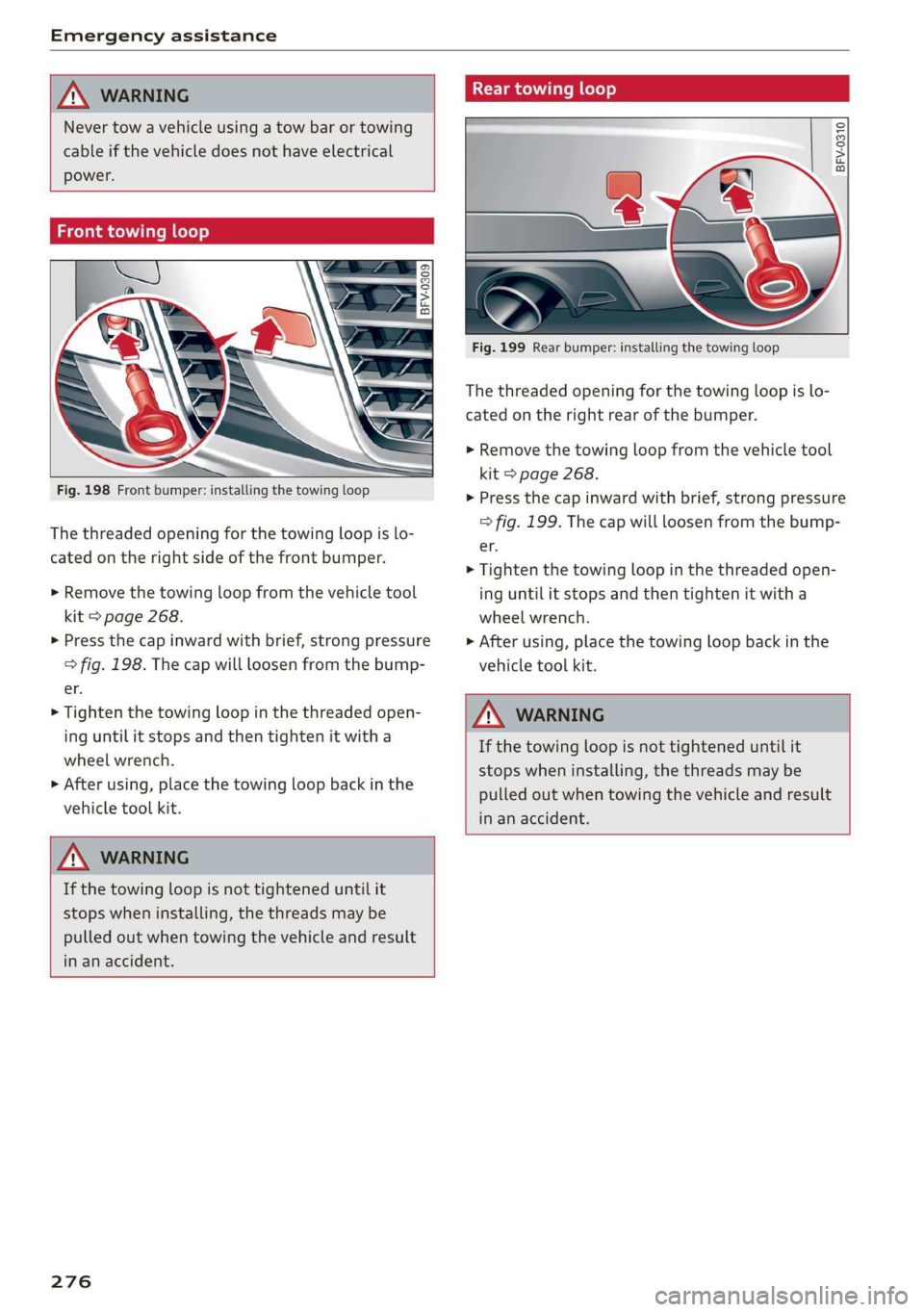
The threaded opening for the towing loop is lo-
cated on the right side of the front bumper.
> Remove the towing loop from the vehicle tool
kit > page 268.
> Press the cap inward with brief, strong pressure
> fig. 198. The cap will loosen from the bump-
er.
> Tighten the towing loop in the threaded open-
ing until it stops and then tighten it with a
wheel wrench.
> After using, place the towing loop back in the
vehicle tool kit.
ZX WARNING
If the towing loop is not tightened until it
stops when installing, the threads may be
pulled out when towing the vehicle and result
in an accident.
276
Rear towing loop
BFV-0310
Fig. 199 Rear bumper: installing the towing loop
The threaded opening for the towing loop is lo-
cated on the right rear of the bumper.
> Remove the towing loop from the vehicle tool
kit > page 268.
> Press the cap inward with brief, strong pressure
> fig. 199. The cap will loosen from the bump-
er.
> Tighten the towing loop in the threaded open-
ing until it stops and then tighten it with a
wheel wrench.
» After using, place the towing loop back in the
vehicle tool kit.
Z\ WARNING
If the towing loop is not tightened until it
stops when installing, the threads may be
pulled out when towing the vehicle and result
in an accident.
Page 279 of 304
8S58012721BA
Fuses and bulbs
Fuses and bulbs
Fuses
Replacing fuses
S 6
= o
q
= 2 % a.
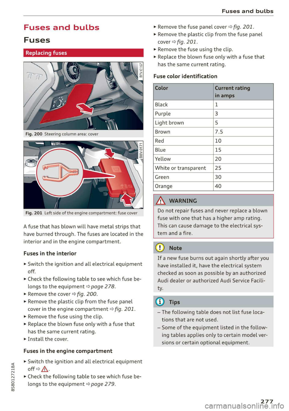
Fig. 201 Left side of the engine compartment: fuse cover
A fuse that has blown will have metal strips that
have burned through. The fuses are located in the
interior and in the engine compartment.
Fuses in the interior
> Switch the ignition and all electrical equipment
off.
> Check the following table to see which fuse be-
longs to the equipment > page 278.
» Remove the cover > fig. 200.
> Remove the plastic clip from the fuse panel
cover in the engine compartment © fig. 201.
> Remove the fuse using the clip.
> Replace the blown fuse only with a fuse that
has the same current rating.
> Install the cover.
Fuses in the engine compartment
> Switch the ignition and all electrical equipment
off > A\.
> Check the following table to see which fuse be-
longs to the equipment > page 279.
> Remove the fuse panel cover > fig. 201.
> Remove the plastic clip from the fuse panel
cover > fig. 201.
> Remove the fuse using the clip.
> Replace the blown fuse only with a fuse that
has the same current rating.
Fuse color identification
Color Current rating
in amps
Black 1
Purple 3
Light brown 5
Brown 1d
Red 10
Blue 15
Yellow 20
White or transparent [25
Green 30
Orange 40
Z\ WARNING
Do not repair fuses and never replace a blown
fuse with one that has a higher amp rating.
This can cause damage to the electrical sys-
tem and a fire.
CG) Note
If a new fuse burns out again shortly after you
have installed it, have the electrical system
checked as soon as possible by an authorized
Audi dealer or authorized Audi Service Facili-
ty.
@) Tips
— The following table does not list fuse loca-
tions that are not used.
— Some of the equipment listed in the follow-
ing tables applies only to certain model ver-
sions or certain optional equipment.
277
Page 280 of 304
![AUDI TT ROADSTER 2019 Owners Manual Fuses and bulbs
Interior fuse assignment
ft
pl Bel Fe
» BEBE ERED
Poo
ns
[24] 25) rao) 27) Fe Ra
23 |
Fsacsomeemr STE 42)
eases eres] b
ro Wa a i ee
1F52) FOL
Re
B8V-0217
AUDI TT ROADSTER 2019 Owners Manual Fuses and bulbs
Interior fuse assignment
ft
pl Bel Fe
» BEBE ERED
Poo
ns
[24] 25) rao) 27) Fe Ra
23 |
Fsacsomeemr STE 42)
eases eres] b
ro Wa a i ee
1F52) FOL
Re
B8V-0217](/img/6/57667/w960_57667-279.png)
Fuses and bulbs
Interior fuse assignment
ft
pl Bel Fe
» BEBE ERED
Poo
ns
[24] 25) rao) 27) Fe Ra
23 |
Fsacsomeemr STE 42)
eases eres] b
ro Wa a i ee
1F52) FOL
Re
B8V-0217
No. | Equipment
F20 | Power lumbar support adjustment
Front passenger's side neck heating (Road-
F22
ster)
Right vehicle electrical system control
F24
module
F25 | Driver side door
F26 | Seat heating
Vehicle electrical system control module
Fae (terminal 30)
F28 | AMI High media port
F29 | Vehicle electrical system control module
F32 | Driver assistance systems
F33 | Airbag
Sockets, interior sound, tail light switch,
F34 | temperature sensor, oil level sensor, neck
heating, garage door opener
Fig. 202 Vehicle interior: fuse assignment
No. Equipment
Diagnosis, headlight range control, air
quality sensor, automatic dimming rear-
view mirror, center instrument panel
switch module
F35
F4 Central computer processor (MIB-2) F36 | Right cornering light / right LED headlight
FS Gateway (diagnostics) F37 | Left cornering light / left LED headlight
Fo Selector lever (automatic transmission)
F7
Climate control system controls, rear win-
dow defogger, tire pressure monitoring
Engine control module, ESC control mod-
F38
ule
F39 | Front passenger side door
F8
Switch for the electromechanical parking
brake, light switch, rain/light sensor, inte-
rior lighting, diagnostic connector, roof
electronics F40
| Cigarette lighter, sockets
F41 | Fuel tank diagnosis
F42 | Central locking area
FQ Steering column switch module
F44 | All wheel drive clutch control module
F10 Vehicle positioning
F45 | Power adjustable driver's side seat
Fll
All wheel drive clutch, left vehicle electri-
cal system control module
F46 | Driver's side neck heating (Roadster)
F49 | Engine start, clutch sensor
F12 Infotainment components
F52 | Control module for suspension control
F1l4 Climate control system blower fan
F53 | Rear window defogger
Fis Electronic steering column lock
F16
Infotainment system components, safety
belt microphone
F17 Instrument cluster
F18 Rearview camera
F19
Convenience access control module
278
The power seats* are protected via circuit break-
ers that automatically switch on after a few sec-
onds after the overload has been reduced.