ESP BMW 135IS COUPE 2013 User Guide
[x] Cancel search | Manufacturer: BMW, Model Year: 2013, Model line: 135IS COUPE, Model: BMW 135IS COUPE 2013Pages: 284, PDF Size: 6.93 MB
Page 42 of 284
41
Opening and closing
Controls
Convertible: window and convertible
top operation
With the ignition at radio readiness or beyond,
you can open and close the windows and the
convertible top when a remote control is
located inside the vehicle.
Unlocking the trunk lid separately
Press the button on the ou
tside of the trunk lid.
This corresponds to pressing the button. If the vehicle detects that a remote con-
trol has been accident ally left inside the
locked vehicle after the trunk lid is closed, the
lid will reopen. The haza rd warning flashers
flash and a signal sounds. <
Switching on radio readiness
Pressing the Start/Stop button switches on
radio readiness.
Do not depress the brake or the clutch; other-
wise, the engine will start immediately.
Starting the engine
The engine can be started or the ignition can be
switched on when a remote control is inside the
vehicle. It is not necessa ry to insert a remote
control into the ignition lock, refer to page 61.
Switching off the engine in cars with
automatic transmission
The engine can only be switched off when the
selector lever is in po sition P, refer to page 63.
To switch the engine off when the selector lever
is in position N, the remote control must be in
the ignition lock.
Malfunctions
Local radio waves can in terfere with the func-
tion of Comfort Access, for example when a
mobile phone is in the immediate vicinity of the
remote control or by when a mobile phone is
being charged in the vehicle. If this happens, open and close the vehicle via
the buttons on the remote control or using the
integrated key. To star
t the engine afterward,
insert the remote control into the ignition lock.
Warning lamps
The warning lamp in the instrument
cluster lights up when you attempt to
start the engine: the engine cannot
be started. The remote co ntrol is not inside the
vehicle or is malfunctio ning. Take the remote
control with you inside the vehicle or have it
checked. If necessary, insert another remote
control into the ignition lock.
The warning lamp in the instrument
cluster lights up wh ile the engine is
running: the remote control is no
longer inside the vehicle. After the engine is
switched off, the engine can only be restarted
within approx. 10 seconds.
The indicator lamp in the instrument
cluster comes on and a message
appears on the Control Display:
replace the battery in the remote control.
Replacing the battery
The remote control for Comfort Access con-
tains a battery that will need to be replaced from
time to time.
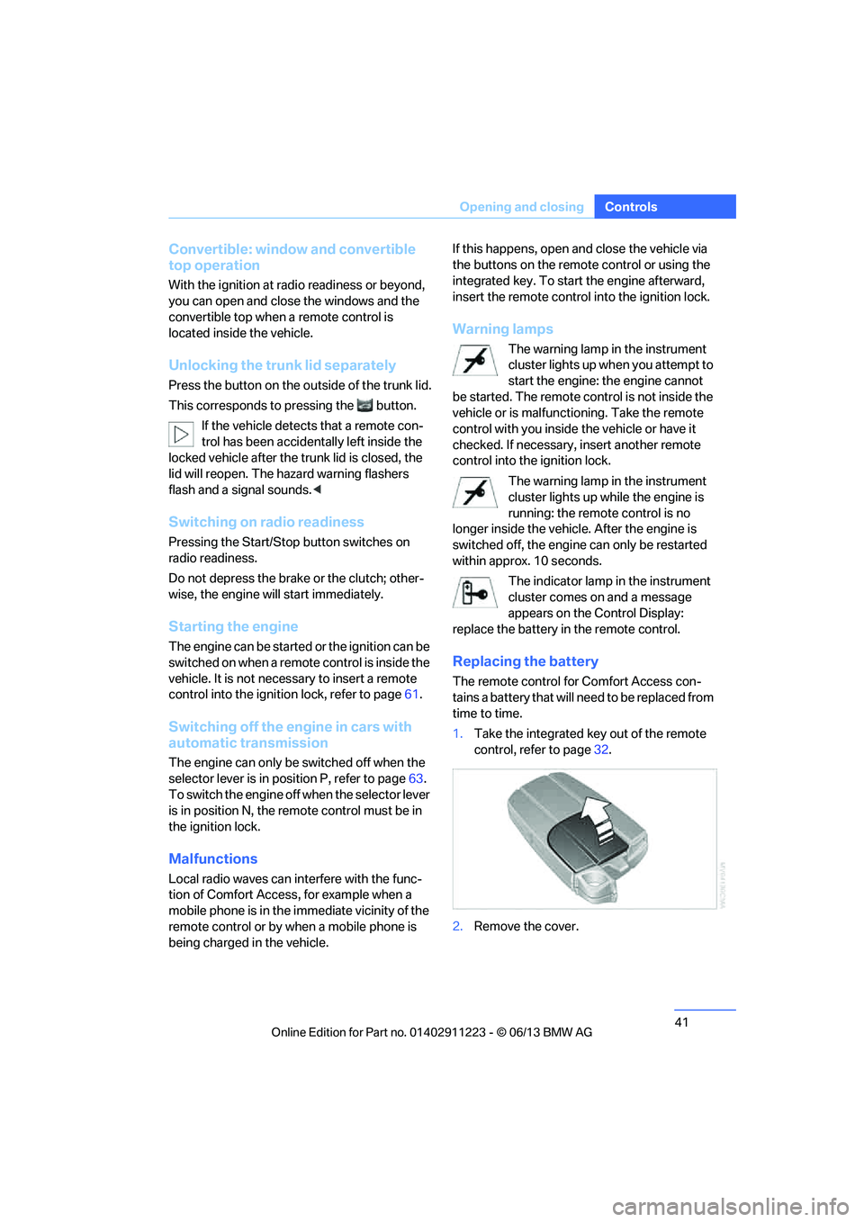
1. Take the integrated ke y out of the remote
control, refer to page 32.
2. Remove the cover.
00320051004F004C00510048000300280047004C0057004C005200510003
Page 44 of 284
43
Opening and closing
Controls
After switching off the ignition
When the remote control
is removed or the igni-
tion is switched off, you can still operate the
windows for approx. 1 minute as long as no
door has been opened.
Convenient opening and closing
For Convenient opening and closing using the
remote control, refer to page 34. For Conve-
nient closing using Comfort Access, refer to
Locking on page 40.
Pinch protection system
If the closing force exceeds a specific value as a
power window closes, the closing action is
interrupted and the window reopens slightly.
Despite the pinch protection system
check and clear the window's travel path
prior to closing it; otherwise, the safety system
might fail to detect certain kinds of obstruc-
tions, such as thin objects, and the window
would continue closing.
Do not install any accessories that might inter-
fere with window movement. Otherwise, the
pinch protection system could be impaired.
Convertible: the rear windows are not equipped
with pinch protection. Therefore, watch them
closely when closing to avoid personal injury. <
Closing without pinch protection
If there is an external danger, or if ice on the
windows, etc., prevents you from closing the
windows normally, proceed as follows:
1.Pull the switch past the resistance point and
hold it there. Pinch protection is limited and
the window reopens slightly if the closing
force exceeds a certain value.
2. Pull the switch again past the resistance
point within approx. 4 seconds and hold it
there. The window closes without pinch
protection.
Coupe: glass roof, electric
To prevent injuries, watch the glass roof
while closing it.
Take the remote contro l with you when you
leave the car; otherwise, children could operate
the roof and possibly injure themselves. <
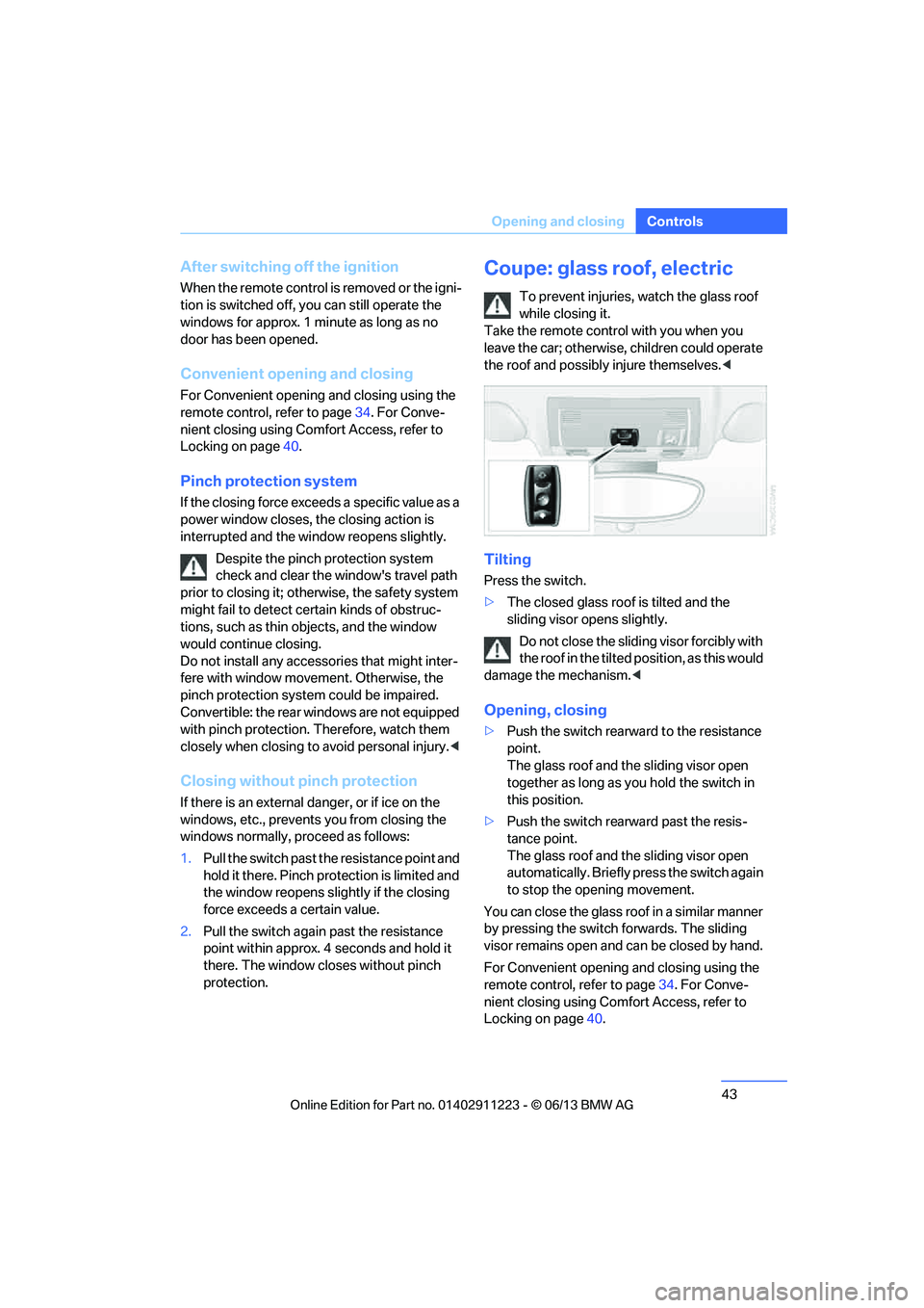
Tilting
Press the switch.
>The closed glass roof is tilted and the
sliding visor opens slightly.
Do not close the sliding visor forcibly with
the roof in the tilted position, as this would
damage the mechanism. <
Opening, closing
>Push the switch rearward to the resistance
point.
The glass roof and the sliding visor open
together as long as you hold the switch in
this position.
> Push the switch rearward past the resis-
tance point.
The glass roof and the sliding visor open
automatically. Briefly press the switch again
to stop the opening movement.
You can close the glass roof in a similar manner
by pressing the switch forwards. The sliding
visor remains open and can be closed by hand.
For Convenient opening and closing using the
remote control, refer to page 34. For Conve-
nient closing using Comfort Access, refer to
Locking on page 40.
00320051004F004C00510048000300280047004C0057004C005200510003
Page 45 of 284
44
ControlsOpening and closing
After switching off the ignition
When the remote control is removed or the igni-
tion is switched off, you can still operate the roof
for approx. 1 minute as long as no door has
been opened.
Pinch protection system
If the glass roof encounters an obstruction dur-
ing closing from approximately the middle of
the opening in the roof, or during closing from
the tilted position, the closing movement is
interrupted and the glass roof is opened again
slightly.
Despite the pinch protection system
check and clear the roof's travel path prior
to closing it; otherwise, the safety system might
fail to detect certain kinds of obstructions, such
as very thin objects, and the roof would con-
tinue closing. <
Closing without pinch protection
If there is an external danger, press the switch
forward past the resistan ce point and hold it
there. The roof closes without pinch protection.
Following interruptions in electrical
power supply
After a power failure, there is a possibility that
the glass roof can only be tilted. The system
must be initialized. BMW recommends having
this work performed at your BMW center.
Convertible: convertible top
The fully automatic top combines reliable
weather protection with simple and easy-to-
use operation.
The following tips will enhance your driving
pleasure in your Convertible:
> It is recommended that you close the con-
vertible top whenever the vehicle is parked.
The closed convertible top not only pro-
tects the vehicle interior from damage due
to unforeseen bad we ather, but also pro- vides a certain degree of protection against
theft. However, even when the top is
closed, valuables should
only be stored in
the locked trunk.
> Do not mount any roof rack systems on the
convertible top.
> If the top is opened while it is wet, e.g. after
driving in the rain, water may drip into the
trunk. If necessary, remove items from the
trunk beforehand to av oid water stains or
soiling.
At temperatures below +14 7/–10 6, do
not move the convertible top as this could
result in damage.
Do not keep the convertible top in the convert-
ible top box for longer than one day if it is wet;
otherwise, the moistu re may cause damage.
Do not place objects on the convertible top, as
otherwise they may fall off when you operate
the convertible top and cause damage or injury.
Never move the converti ble top when the roll-
over protection system is in the activated
position.
Always completely finish the operation of the
convertible top. Driving with the convertible top
incompletely opened or closed can result in
damage or injury.
Do not reach into the mechanism during the
opening or closing procedure. Keep children
away from the opening/closing path of the
convertible top.
For safety reasons, only operate the convertible
top while the vehicle is standing. <
While opening and closing, the convert-
ible top pivots upward. When operating
the convertible top in a garage, under a bridge,
etc., ensure that there are at least 6.5 ft/2 m of
headroom; otherwise, the vehicle may be
damaged. <
00320051004F004C00510048000300280047004C0057004C005200510003
Page 51 of 284
50
ControlsAdjustments
injure your abdomen in the event of a frontal
collision. Avoid wearing bulky clothing and
regularly pull the belt in the upper-body area
taut; otherwise, its rest raining effect could be
impaired. <
Safety belts, refer to page 54.
Seats
Note before adjusting
Never attempt to adjust your seat while
the vehicle is moving. The seat could
respond with unexpected movement, and the
ensuing loss of vehicle co ntrol could lead to an
accident.
On the front passenger seat as well, do not
incline the backrest too fa r to the rear while the
vehicle is being driven; otherwise, there is a
danger in the event of an accident of sliding
under the safety belt, eliminating the protection
normally provided by the belt.<
Comply with the instructions on head restraint
height on page 52, and on damaged safety
belts on page 55.
Manual adjustment
Observe the adjustment instructions
above to ensure the best possible
personal protection. <
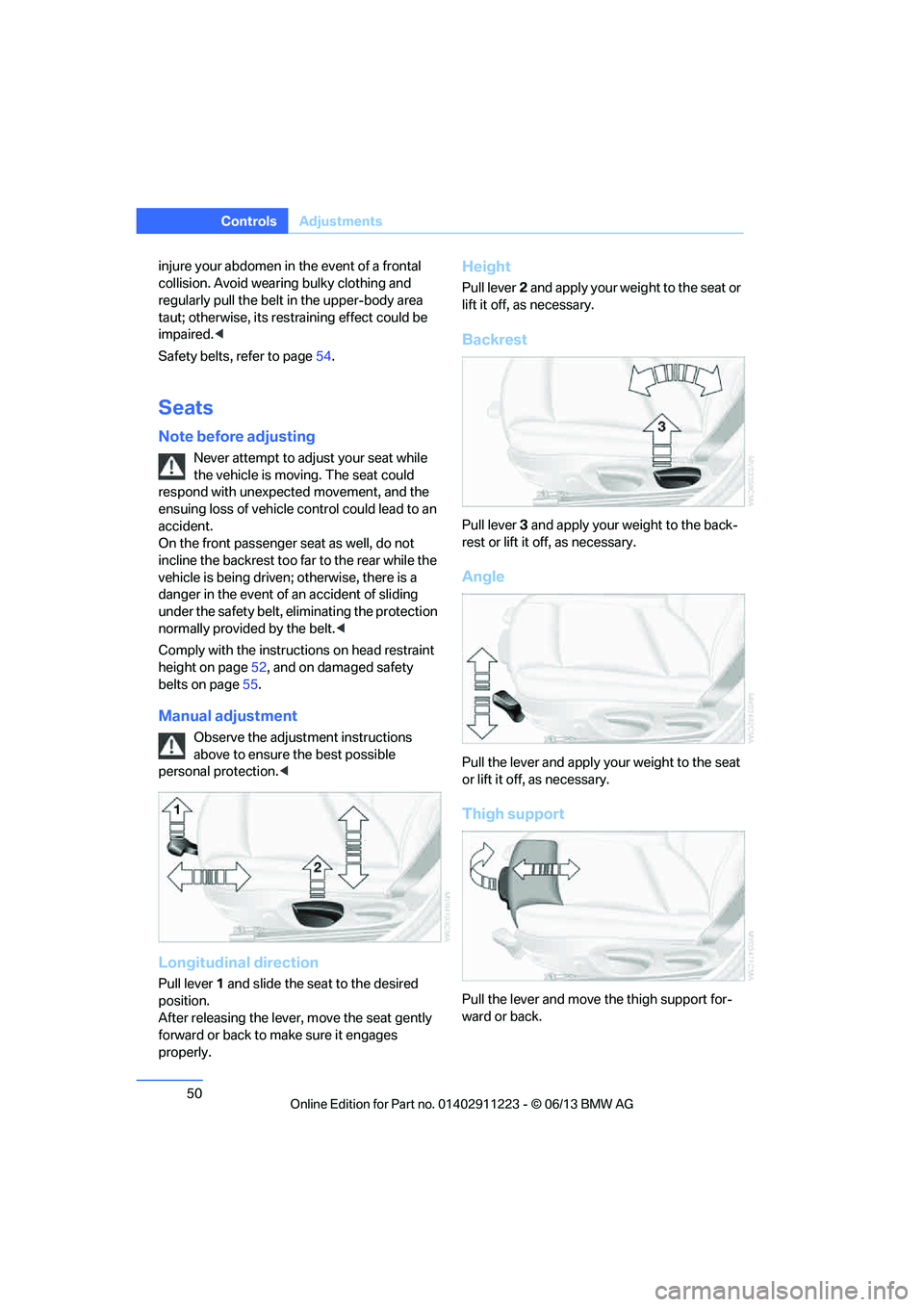
Longitudinal direction
Pull lever1 and slide the seat to the desired
position.
After releasing the lever, move the seat gently
forward or back to ma ke sure it engages
properly.
Height
Pull lever 2 and apply your weight to the seat or
lift it off, as necessary.
Backrest
Pull lever 3 and apply your we ight to the back-
rest or lift it off, as necessary.
Angle
Pull the lever and apply yo ur weight to the seat
or lift it off, as necessary.
Thigh support
Pull the lever and move the thigh support for-
ward or back.
00320051004F004C00510048000300280047004C0057004C005200510003
Page 52 of 284
51
Adjustments
Controls
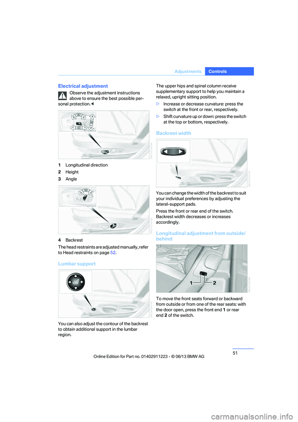
Electrical adjustment
Observe the adjustment instructions
above to ensure the best possible per-
sonal protection. <
1 Longitudinal direction
2 Height
3 Angle
4 Backrest
The head restraints are adjusted manually, refer
to Head restraints on page 52.
Lumbar support
You can also adjust the contour of the backrest
to obtain additional support in the lumbar
region. The upper hips and spinal column receive
supplementary support to help you maintain a
relaxed, upright sitting position.
>
Increase or decrease curvature: press the
switch at the front or rear, respectively.
> Shift curvature up or down: press the switch
at the top or bottom, respectively.
Backrest width
You can change the width of the backrest to suit
your individual prefer ences by adjusting the
lateral-support pads.
Press the front or rear end of the switch.
Backrest width decreases or increases
accordingly.
Longitudinal adjustment from outside/
behind
To move the front seats forward or backward
from outside or from one of the rear seats: with
the door open, press the front end 1 or rear
end 2 of the switch.
00320051004F004C00510048000300280047004C0057004C005200510003
Page 76 of 284
75
Controls overview
Controls
Controls overview
Vehicle equipment
In this chapter, all production, country, and
optional equipment that is offered in the model
range is described. For this reason, descrip-
tions will be given of some equipment that may
not be available in a vehi
cle, for example due to
the special options or national-market version
selected. This also app lies to safety related
functions and systems.
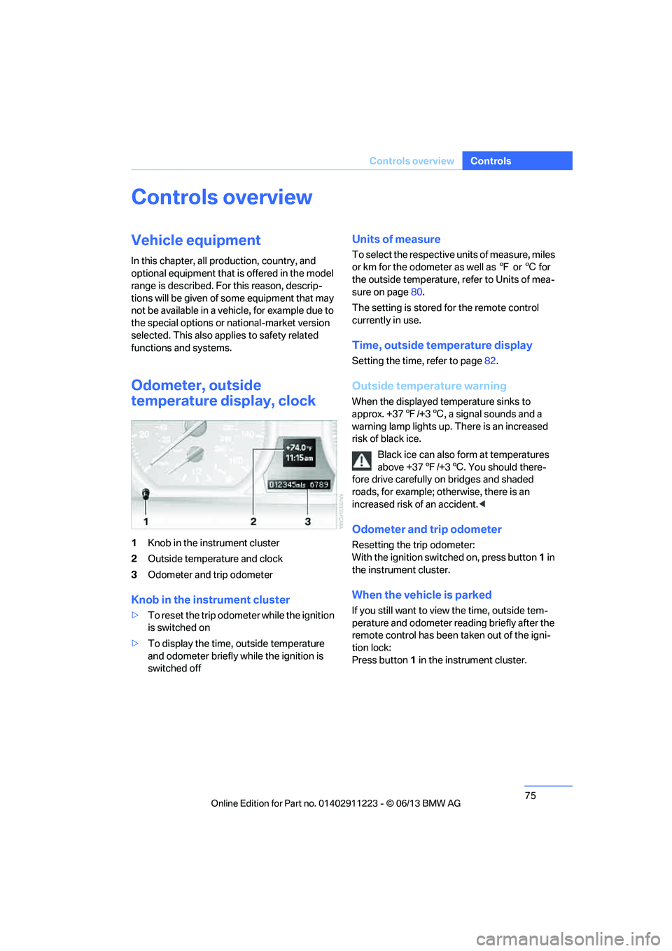
Odometer, outside
temperature display, clock
1 Knob in the instrument cluster
2 Outside temperature and clock
3 Odometer and trip odometer
Knob in the instrument cluster
>To reset the trip odomet er while the ignition
is switched on
> To display the time, outside temperature
and odometer briefly while the ignition is
switched off
Units of measure
To select the respective units of measure, miles
or km for the odometer as well as 7 or 6 for
the outside temperature, refer to Units of mea-
sure on page 80.
The setting is stored for the remote control
currently in use.
Time, outside temperature display
Setting the time, refer to page 82.
Outside temperature warning
When the displayed temperature sinks to
approx. +377/+3 6, a signal sounds and a
warning lamp lights up. There is an increased
risk of black ice.
Black ice can also form at temperatures
above +37 7/+3 6. You should there-
fore drive carefully on bridges and shaded
roads, for example; otherwise, there is an
increased risk of an accident. <
Odometer and trip odometer
Resetting the trip odometer:
With the ignition switched on, press button 1 in
the instrument cluster.
When the vehicle is parked
If you still want to view the time, outside tem-
perature and odometer reading briefly after the
remote control has been taken out of the igni-
tion lock:
Press button 1 in the instrument cluster.
00320051004F004C00510048000300280047004C0057004C005200510003
Page 78 of 284
77
Controls overview
Controls
Computer
Displays in the instrument cluster
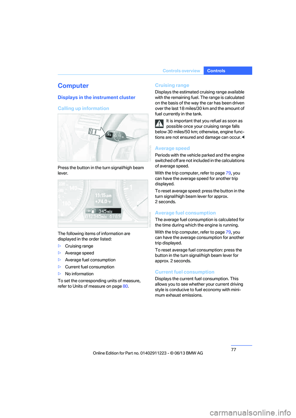
Calling up information
Press the button in the turn signal/high beam
lever.
The following items of information are
displayed in the order listed:
>
Cruising range
> Average speed
> Average fuel consumption
> Current fuel consumption
> No information
To set the corresponding units of measure,
refer to Units of measure on page 80.
Cruising range
Displays the estimated cruising range available
with the remaining fuel. The range is calculated
on the basis of the way the car has been driven
over the last 18 miles/30 km and the amount of
fuel currently in the tank.
It is important that you refuel as soon as
possible once your cruising range falls
below 30 miles/50 km; otherwise, engine func-
tions are not ensured and damage can occur. <
Average speed
Periods with the vehicle parked and the engine
switched off are not included in the calculations
of average speed.
With the trip comp uter, refer to page79, you
can have the average speed for another trip
displayed.
To reset average speed: press the button in the
turn signal/high beam lever for approx.
2seconds.
Average fuel consumption
The average fuel consumption is calculated for
the time during which the engine is running.
With the trip comp uter, refer to page79, you
can have the average consumption for another
trip displayed.
To reset average fuel consumption: press the
button in the turn signal/high beam lever for
approx. 2 seconds.
Current fuel consumption
Displays the current fuel consumption. This
allows you to see whethe r your current driving
style is conducive to fuel economy with mini-
mum exhaust emissions.
00320051004F004C00510048000300280047004C0057004C005200510003
Page 79 of 284
78
ControlsControls overview
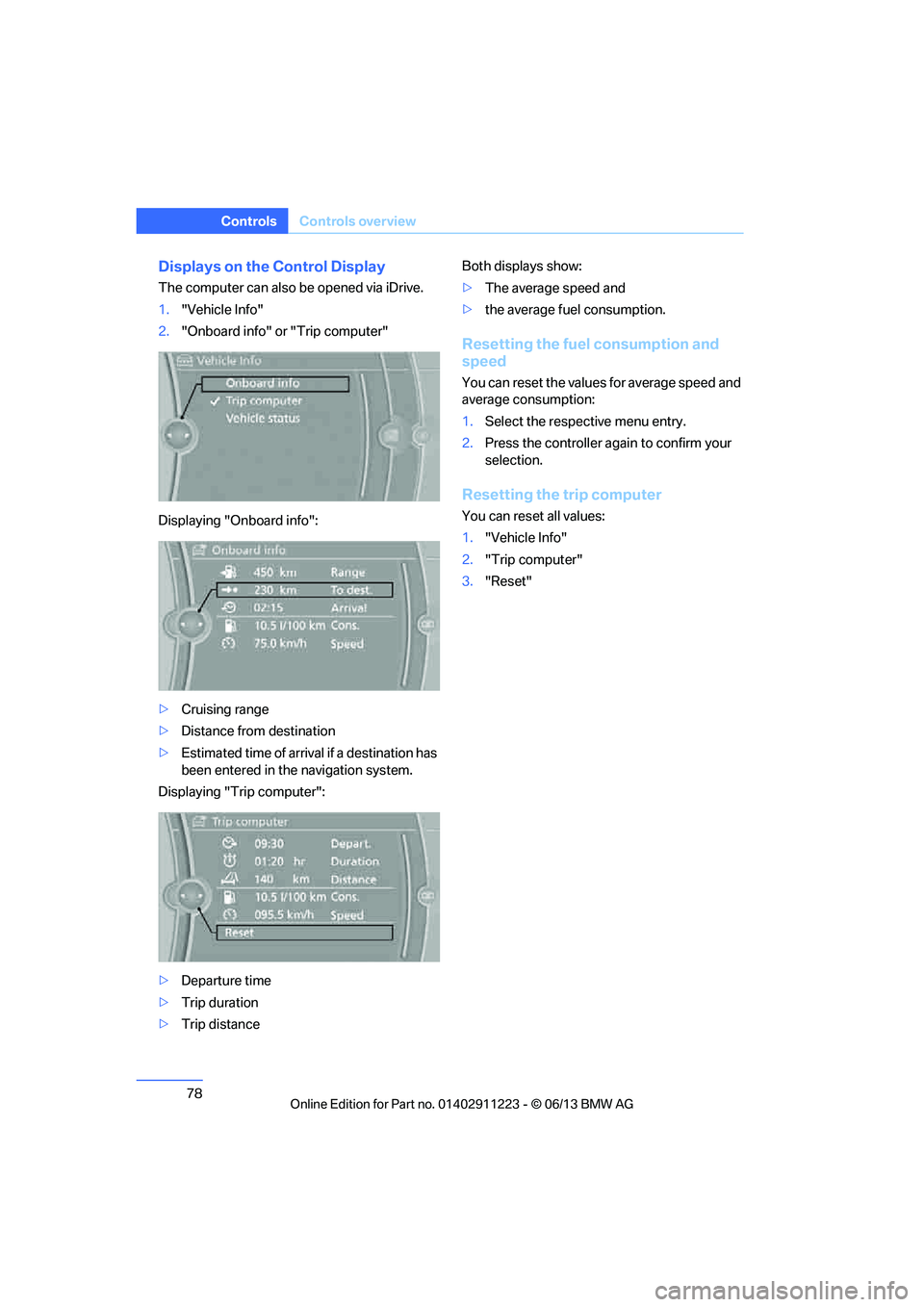
Displays on the Control Display
The computer can also be opened via iDrive.
1."Vehicle Info"
2. "Onboard info" or "Trip computer"
Displaying "Onboard info":
> Cruising range
> Distance from destination
> Estimated time of arrival if a destination has
been entered in the navigation system.
Displaying "Trip computer":
> Departure time
> Trip duration
> Trip distance Both displays show:
>
The average speed and
> the average fuel consumption.
Resetting the fuel consumption and
speed
You can reset the values for average speed and
average consumption:
1.Select the respective menu entry.
2. Press the controller again to confirm your
selection.
Resetting the trip computer
You can reset all values:
1."Vehicle Info"
2. "Trip computer"
3. "Reset"
00320051004F004C00510048000300280047004C0057004C005200510003
Page 81 of 284
80
ControlsControls overview
Units of measure
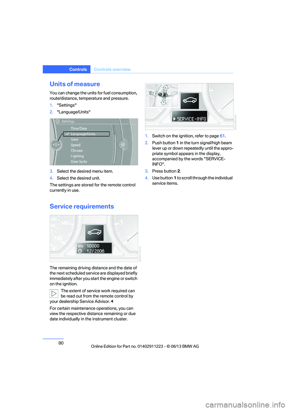
You can change the units for fuel consumption,
route/distance, temperature and pressure.
1."Settings"
2. "Language/Units"
3. Select the desired menu item.
4. Select the desired unit.
The settings are stored for the remote control
currently in use.
Service requirements
The remaining driving distance and the date of
the next scheduled servic e are displayed briefly
immediately after you start the engine or switch
on the ignition.
The extent of service work required can
be read out from the remote control by
your dealership Service Advisor. <
For certain maintenance operations, you can
view the respective distance remaining or due
date individually in the instrument cluster. 1.
Switch on the ignition, refer to page 61.
2. Push button 1 in the turn signal/high beam
lever up or down repe atedly until the appro-
priate symbol appear s in the display,
accompanied by the words "SERVICE-
INFO".
3. Press button 2.
4. Use button 1 to scroll through the individual
service items.
00320051004F004C00510048000300280047004C0057004C005200510003
Page 86 of 284
85
Controls overview
Controls
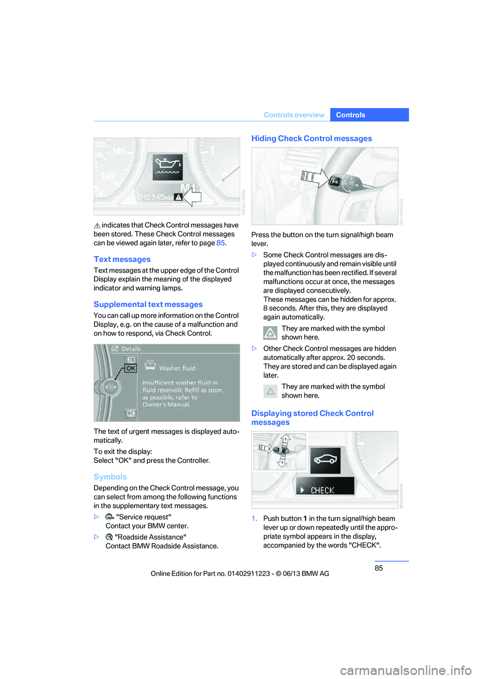
indicates that Check
Control messages have
been stored. These Check Control messages
can be viewed again later, refer to page85.
Text messages
Text messages at the uppe r edge of the Control
Display explain the meaning of the displayed
indicator and warning lamps.
Supplemental text messages
You can call up more information on the Control
Display, e.g. on the cause of a malfunction and
on how to respond, via Check Control.
The text of urgent messages is displayed auto-
matically.
To exit the display:
Select "OK" and press the Controller.
Symbols
Depending on the Check Control message, you
can select from among the following functions
in the supplementary text messages.
> "Service request"
Contact your BMW center.
> "Roadside Assistance"
Contact BMW Roadside Assistance.
Hiding Check Control messages
Press the button on the turn signal/high beam
lever.
> Some Check Control messages are dis-
played continuously an d remain visible until
the malfunction has been rectified. If several
malfunctions occur at once, the messages
are displayed consecutively.
These messages can be hidden for approx.
8 seconds. After this, they are displayed
again automatically.
They are marked with the symbol
shown here.
> Other Check Control messages are hidden
automatically after approx. 20 seconds.
They are stored and can be displayed again
later.
They are marked with the symbol
shown here.
Displaying stored Check Control
messages
1.Push button 1 in the turn signal/high beam
lever up or down repeatedly until the appro-
priate symbol appears in the display,
accompanied by the words "CHECK".
00320051004F004C00510048000300280047004C0057004C005200510003