check engine BMW 3 SERIES 1983 E30 Workshop Manual
[x] Cancel search | Manufacturer: BMW, Model Year: 1983, Model line: 3 SERIES, Model: BMW 3 SERIES 1983 E30Pages: 228, PDF Size: 7.04 MB
Page 157 of 228
21 Steering box (5-Series)-
removal and refitting
4
Removal
Note:If you find that the steering box is
defective, it is not recommended that you
overhaul it. Because of the special tools
needed to do the job, it is best to let your
dealer service department overhaul it for you
(otherwise, fit a new unit). Removal and
refitting the steering box is outlined here.
1On 5-Series E28 (“old-shape”) models,
discharge the hydraulic system by depressing
the brake pedal about 20 times.
2Using a large syringe or hand pump, empty
the power steering fluid reservoir (see Chap-
ter 1).
3Raise the front of the vehicle and support it
securely on axle stands.
4Support the front of the engine with a trolley
jack. Place a block of wood between the jack
head and the sump to protect the sump from
damage.
5Remove the pivot bolts from the inner ends
of the front control arms (see Section 4).
6Remove the nuts from the left and right
engine mountings (see Chapter 2).
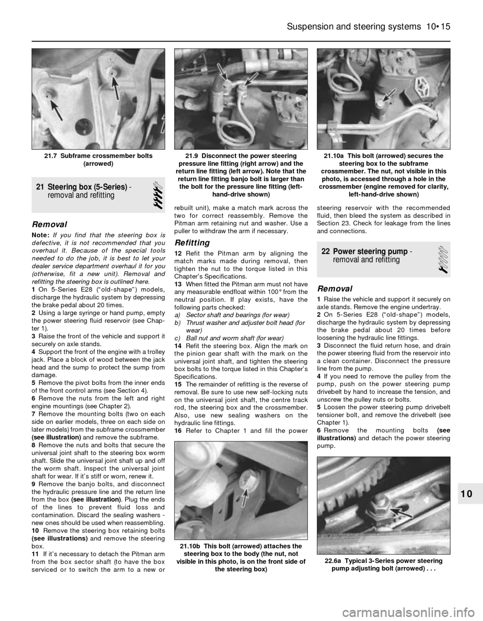
7Remove the mounting bolts (two on each
side on earlier models, three on each side on
later models) from the subframe crossmember
(see illustration)and remove the subframe.
8Remove the nuts and bolts that secure the
universal joint shaft to the steering box worm
shaft. Slide the universal joint shaft up and off
the worm shaft. Inspect the universal joint
shaft for wear. If it’s stiff or worn, renew it.
9Remove the banjo bolts, and disconnect
the hydraulic pressure line and the return line
from the box (see illustration). Plug the ends
of the lines to prevent fluid loss and
contamination. Discard the sealing washers -
new ones should be used when reassembling.
10Remove the steering box retaining bolts
(see illustrations)and remove the steering
box.
11If it’s necessary to detach the Pitman arm
from the box sector shaft (to have the box
serviced or to switch the arm to a new orrebuilt unit), make a match mark across the
two for correct reassembly. Remove the
Pitman arm retaining nut and washer. Use a
puller to withdraw the arm if necessary.
Refitting
12Refit the Pitman arm by aligning the
match marks made during removal, then
tighten the nut to the torque listed in this
Chapter’s Specifications.
13When fitted the Pitman arm must not have
any measurable endfloat within 100° from the
neutral position. If play exists, have the
following parts checked:
a) Sector shaft and bearings (for wear)
b) Thrust washer and adjuster bolt head (for
wear)
c) Ball nut and worm shaft (for wear)
14Refit the steering box. Align the mark on
the pinion gear shaft with the mark on the
universal joint shaft, and tighten the steering
box bolts to the torque listed in this Chapter’s
Specifications.
15The remainder of refitting is the reverse of
removal. Be sure to use new self-locking nuts
on the universal joint shaft, the centre track
rod, the steering box and the crossmember.
Also, use new sealing washers on the
hydraulic line fittings.
16Refer to Chapter 1 and fill the powersteering reservoir with the recommended
fluid, then bleed the system as described in
Section 23. Check for leakage from the lines
and connections.22 Power steering pump-
removal and refitting
1
Removal
1Raise the vehicle and support it securely on
axle stands. Remove the engine undertray.
2On 5-Series E28 (“old-shape”) models,
discharge the hydraulic system by depressing
the brake pedal about 20 times before
loosening the hydraulic line fittings.
3Disconnect the fluid return hose, and drain
the power steering fluid from the reservoir into
a clean container. Disconnect the pressure
line from the pump.
4If you need to remove the pulley from the
pump, push on the power steering pump
drivebelt by hand to increase the tension, and
unscrew the pulley nuts or bolts.
5Loosen the power steering pump drivebelt
tensioner bolt, and remove the drivebelt (see
Chapter 1).
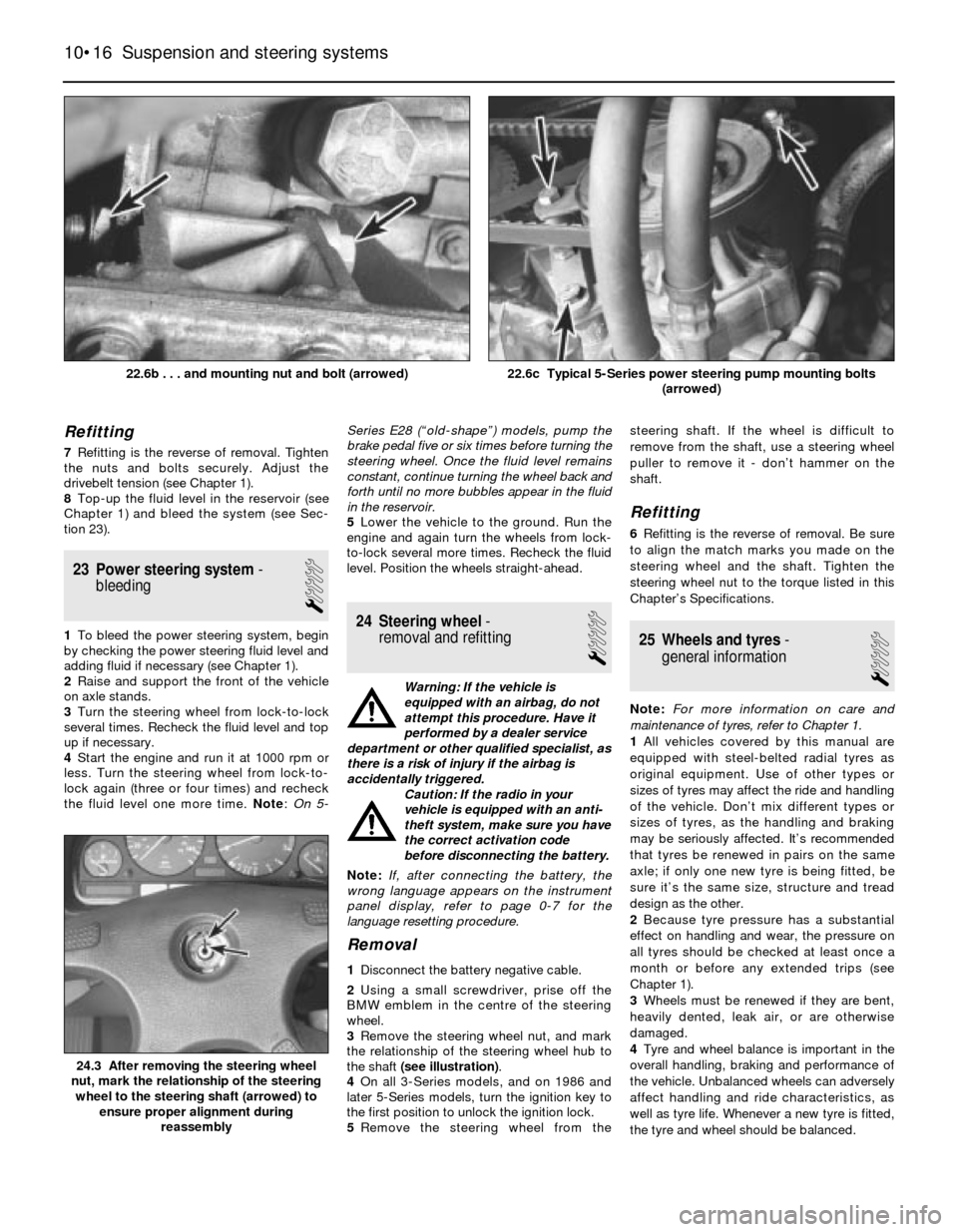
6Remove the mounting bolts (see
illustrations)and detach the power steering
pump.
Suspension and steering systems 10•15
21.10a This bolt (arrowed) secures the
steering box to the subframe
crossmember. The nut, not visible in this
photo, is accessed through a hole in the
crossmember (engine removed for clarity,
left-hand-drive shown)21.9 Disconnect the power steering
pressure line fitting (right arrow) and the
return line fitting (left arrow). Note that the
return line fitting banjo bolt is larger than
the bolt for the pressure line fitting (left-
hand-drive shown)21.7 Subframe crossmember bolts
(arrowed)
22.6a Typical 3-Series power steering
pump adjusting bolt (arrowed) . . .
21.10b This bolt (arrowed) attaches the
steering box to the body (the nut, not
visible in this photo, is on the front side of
the steering box)
10
Page 158 of 228
Refitting
7Refitting is the reverse of removal. Tighten
the nuts and bolts securely. Adjust the
drivebelt tension (see Chapter 1).
8Top-up the fluid level in the reservoir (see
Chapter 1) and bleed the system (see Sec-
tion 23).
23 Power steering system-
bleeding
1
1To bleed the power steering system, begin
by checking the power steering fluid level and
adding fluid if necessary (see Chapter 1).
2Raise and support the front of the vehicle
on axle stands.
3Turn the steering wheel from lock-to-lock
several times. Recheck the fluid level and top
up if necessary.
4Start the engine and run it at 1000 rpm or
less. Turn the steering wheel from lock-to-
lock again (three or four times) and recheck
the fluid level one more time. Note:On 5-Series E28 (“old-shape”) models, pump the
brake pedal five or six times before turning the
steering wheel. Once the fluid level remains
constant, continue turning the wheel back and
forth until no more bubbles appear in the fluid
in the reservoir.
5Lower the vehicle to the ground. Run the
engine and again turn the wheels from lock-
to-lock several more times. Recheck the fluid
level. Position the wheels straight-ahead.24 Steering wheel-
removal and refitting
1
Warning: If the vehicle is
equipped with an airbag, do not
attempt this procedure. Have it
performed by a dealer service
department or other qualified specialist, as
there is a risk of injury if the airbag is
accidentally triggered.
Caution: If the radio in your
vehicle is equipped with an anti-
theft system, make sure you have
the correct activation code
before disconnecting the battery.
Note: If, after connecting the battery, the
wrong language appears on the instrument
panel display, refer to page 0-7 for the
language resetting procedure.
Removal
1Disconnect the battery negative cable.
2Using a small screwdriver, prise off the
BMW emblem in the centre of the steering
wheel.
3Remove the steering wheel nut, and mark
the relationship of the steering wheel hub to
the shaft (see illustration).
4On all 3-Series models, and on 1986 and
later 5-Series models, turn the ignition key to
the first position to unlock the ignition lock.
5Remove the steering wheel from thesteering shaft. If the wheel is difficult to
remove from the shaft, use a steering wheel
puller to remove it - don’t hammer on the
shaft.
Refitting
6Refitting is the reverse of removal. Be sure
to align the match marks you made on the
steering wheel and the shaft. Tighten the
steering wheel nut to the torque listed in this
Chapter’s Specifications.
25 Wheels and tyres-
general information
1
Note:For more information on care and
maintenance of tyres, refer to Chapter 1.
1All vehicles covered by this manual are
equipped with steel-belted radial tyres as
original equipment. Use of other types or
sizes of tyres may affect the ride and handling
of the vehicle. Don’t mix different types or
sizes of tyres, as the handling and braking
may be seriously affected. It’s recommended
that tyres be renewed in pairs on the same
axle; if only one new tyre is being fitted, be
sure it’s the same size, structure and tread
design as the other.
2Because tyre pressure has a substantial
effect on handling and wear, the pressure on
all tyres should be checked at least once a
month or before any extended trips (see
Chapter 1).
3Wheels must be renewed if they are bent,
heavily dented, leak air, or are otherwise
damaged.
4Tyre and wheel balance is important in the
overall handling, braking and performance of
the vehicle. Unbalanced wheels can adversely
affect handling and ride characteristics, as
well as tyre life. Whenever a new tyre is fitted,
the tyre and wheel should be balanced.
10•16 Suspension and steering systems
24.3 After removing the steering wheel
nut, mark the relationship of the steering
wheel to the steering shaft (arrowed) to
ensure proper alignment during
reassembly
22.6c Typical 5-Series power steering pump mounting bolts
(arrowed)22.6b . . . and mounting nut and bolt (arrowed)
Page 160 of 228
11
1 General information
These models feature an all-steel welded
construction, where the floorpan and body
components are welded together and
attached to separate front and rear subframe
assemblies. Certain components are
particularly vulnerable to accident damage,
and can be unbolted and repaired or renewed.
Among these parts are the body mouldings,
bumpers, bonnet, doors, tailgate, and all
glass.
Only general body maintenance procedures
and body panel repair procedures within the
scope of the do-it-yourselfer are included in
this Chapter.
2 Bodywork and underframe-
maintenance
1
The general condition of a vehicle’s
bodywork is the one thing that significantly
affects its value. Maintenance is easy, but
needs to be regular. Neglect, particularly after
minor damage, can lead quickly to further
deterioration and costly repair bills. It is
important also to keep watch on those parts
of the vehicle not immediately visible, for
instance the underside, inside all the wheelarches, and the lower part of the engine
compartment.
The basic maintenance routine for the
bodywork is washing - preferably with a lot of
water, from a hose. This will remove all the
loose solids which may have stuck to the
vehicle. It is important to flush these off in
such a way as to prevent grit from scratching
the finish. The wheel arches and underframe
need washing in the same way, to remove any
accumulated mud, which will retain moisture
and tend to encourage rust. Paradoxically
enough, the best time to clean the underframe
and wheel arches is in wet weather, when the
mud is thoroughly wet and soft. In very wet
weather, the underframe is usually cleaned of
large accumulations automatically, and this is
a good time for inspection.
Periodically, except on vehicles with a wax-
based underbody protective coating, it is a
good idea to have the whole of the
underframe of the vehicle steam-cleaned,
engine compartment included, so that a
thorough inspection can be carried out to see
what minor repairs and renovations are
necessary. Steam-cleaning is available at
many garages, and is necessary for the
removal of the accumulation of oily grime,
which sometimes is allowed to become thick
in certain areas. If steam-cleaning facilities are
not available, there are some excellent grease
solvents available which can be brush-
applied; the dirt can then be simply hosed off.
Note that these methods should not be usedon vehicles with wax-based underbody
protective coating, or the coating will be
removed. Such vehicles should be inspected
annually, preferably just prior to Winter, when
the underbody should be washed down, and
any damage to the wax coating repaired.
Ideally, a completely fresh coat should be
applied. It would also be worth considering
the use of such wax-based protection for
injection into door panels, sills, box sections,
etc, as an additional safeguard against rust
damage, where such protection is not
provided by the vehicle manufacturer.
After washing paintwork, wipe off with a
chamois leather to give an unspotted clear
finish. A coat of clear protective wax polish will
give added protection against chemical
pollutants in the air. If the paintwork sheen has
dulled or oxidised, use a cleaner/polisher
combination to restore the brilliance of the
shine. This requires a little effort, but such
dulling is usually caused because regular
washing has been neglected. Care needs to be
taken with metallic paintwork, as special non-
abrasive cleaner/polisher is required to avoid
damage to the finish. Always check that the
door and ventilator opening drain holes and
pipes are completely clear, so that water can
be drained out. Brightwork should be treated in
the same way as paintwork. Windscreens and
windows can be kept clear of the smeary film
which often appears, by the use of proprietary
glass cleaner. Never use any form of wax or
other body or chromium polish on glass.
Chapter 11 Bodywork and fittings
Bodywork and underframe - maintenance . . . . . . . . . . . . . . . . . . . . 2
Bodywork repair - major damage . . . . . . . . . . . . . . . . . . . . . . . . . . . 6
Bodywork repair - minor damage . . . . . . . . . . . . . . . . . . . . . . . . . . . 5
Bonnet - removal, refitting and adjustment . . . . . . . . . . . . . . . . . . . . 10
Boot lid/tailgate - removal, refitting and adjustment . . . . . . . . . . . . . 14
Bumpers - removal and refitting . . . . . . . . . . . . . . . . . . . . . . . . . . . . 11
Door - removal, refitting and adjustment . . . . . . . . . . . . . . . . . . . . . 13
Door trim panel - removal and refitting . . . . . . . . . . . . . . . . . . . . . . . 12
Door window glass - removal and refitting . . . . . . . . . . . . . . . . . . . . 16
Door window regulator - removal and refitting . . . . . . . . . . . . . . . . . 17
Exterior mirror - removal and refitting . . . . . . . . . . . . . . . . . . . . . . . . 18Fixed glass - renewal . . . . . . . . . . . . . . . . . . . . . . . . . . . . . . . . . . . . 8
General information . . . . . . . . . . . . . . . . . . . . . . . . . . . . . . . . . . . . . . 1
Hinges and locks - maintenance . . . . . . . . . . . . . . . . . . . . . . . . . . . . 7
Interior trim - maintenance . . . . . . . . . . . . . . . . . . . . . . . . . . . . . . . . 3
Latch, lock cylinder and handles - removal, refitting and
adjustment . . . . . . . . . . . . . . . . . . . . . . . . . . . . . . . . . . . . . . . . . . . 15
Radiator grille - removal and refitting . . . . . . . . . . . . . . . . . . . . . . . . 9
Seat belt check . . . . . . . . . . . . . . . . . . . . . . . . . . . . . . . . . . . . . . . . . 21
Seats - removal and refitting . . . . . . . . . . . . . . . . . . . . . . . . . . . . . . . 20
Steering column shrouds - removal and refitting . . . . . . . . . . . . . . . 19
Upholstery and carpets - maintenance . . . . . . . . . . . . . . . . . . . . . . . 4
11•1
Easy,suitable for
novice with little
experienceFairly easy,suitable
for beginner with
some experienceFairly difficult,
suitable for competent
DIY mechanic
Difficult,suitable for
experienced DIY
mechanicVery difficult,
suitable for expert
DIY or professional
Degrees of difficulty Contents
Page 169 of 228
12
Chapter 12 Body electrical systems
Bulb renewal . . . . . . . . . . . . . . . . . . . . . . . . . . . . . . . . . . . . . . . . . . . 15
Central locking system - description and check . . . . . . . . . . . . . . . . 20
Cruise control system - description and check . . . . . . . . . . . . . . . . 19
Direction indicator/hazard warning flasher - check and renewal . . . 5
Electric windows - description and check . . . . . . . . . . . . . . . . . . . . 21
Electrical system fault finding - general information . . . . . . . . . . . . . 2
Fuses - general information . . . . . . . . . . . . . . . . . . . . . . . . . . . . . . . 3
General information . . . . . . . . . . . . . . . . . . . . . . . . . . . . . . . . . . . . . . 1
Headlight housing - removal and refitting . . . . . . . . . . . . . . . . . . . . . 14
Headlights - adjustment . . . . . . . . . . . . . . . . . . . . . . . . . . . . . . . . . . 13
Headlights - bulb renewal . . . . . . . . . . . . . . . . . . . . . . . . . . . . . . . . . 12Heated rear window - check and repair . . . . . . . . . . . . . . . . . . . . . . 17
Ignition switch - removal and refitting . . . . . . . . . . . . . . . . . . . . . . . . 7
Instrument cluster - removal and refitting . . . . . . . . . . . . . . . . . . . . . 10
Radio - removal and refitting . . . . . . . . . . . . . . . . . . . . . . . . . . . . . . . 8
Radio aerial - removal and refitting . . . . . . . . . . . . . . . . . . . . . . . . . . 9
Relays - general information . . . . . . . . . . . . . . . . . . . . . . . . . . . . . . . 4
Service Indicator (SI) board - general information . . . . . . . . . . . . . . 11
Steering column switches - removal and refitting . . . . . . . . . . . . . . . 6
Supplemental Restraint System (SRS) - general information . . . . . . 18
Windscreen/tailgate wiper motor - removal and refitting . . . . . . . . . 16
Wiring diagrams - general information . . . . . . . . . . . . . . . . . . . . . . . 22
12•1
Easy,suitable for
novice with little
experienceFairly easy,suitable
for beginner with
some experienceFairly difficult,
suitable for competent
DIY mechanic
Difficult,suitable for
experienced DIY
mechanicVery difficult,
suitable for expert
DIY or professional
Degrees of difficulty Contents
1 General information
The chassis electrical system of this vehicle
is of 12-volt, negative earth type. Power for
the lights and all electrical accessories is
supplied by a lead/acid-type battery, which is
charged by the alternator.
This Chapter covers repair and service
procedures for various chassis (non-engine
related) electrical components. For
information regarding the engine electrical
system components (battery, alternator,
distributor and starter motor), see Chapter 5.
Warning: To prevent electrical
short-circuits, fires and injury,
always disconnect the battery
negative terminal before
checking, repairing or renewing electrical
components.
Caution: If the radio in your
vehicle is equipped with an anti-
theft system, make sure you have
the correct activation code
before disconnecting the battery, Refer to
the information on page 0-7 at the front of
this manual before detaching the cable.
Note: If, after connecting the battery, the
wrong language appears on the instrument
panel display, refer to page 0-7 for the
language resetting procedure.
2 Electrical system fault
finding- general information
2
A typical electrical circuit consists of an
electrical component, any switches, relays,
motors, fuses, fusible links or circuit breakers,
etc related to that component, and the wiring
and connectors that link the components to
both the battery and the chassis. To help you
pinpoint an electrical circuit problem, wiring
diagrams are included at the end of this book.
Before tackling any troublesome electrical
circuit, first study the appropriate wiring
diagrams to get a complete understanding of
what makes up that individual circuit.
Troublespots, for instance, can often be
isolated by noting if other components related
to that circuit are routed through the same
fuse and earth connections.
Electrical problems usually stem from
simple causes such as loose or corroded
connectors, a blown fuse, a melted fusible
link, or a bad relay. Inspect all fuses, wires
and connectors in a problem circuit first.
The basic tools needed include a circuit
tester, a high-impedance digital voltmeter, a
continuity tester and a jumper wire with an in-
line circuit breaker for bypassing electrical
components. Before attempting to locate or
define a problem with electrical testinstruments, use the wiring diagrams to
decide where to make the necessary
connections.
Voltage checks
Perform a voltage check first when a circuit
is not functioning properly. Connect one lead
of a circuit tester to either the negative battery
terminal or a known good earth.
Connect the other lead to a connector in
the circuit being tested, preferably nearest to
the battery or fuse. If the bulb of the tester
lights up, voltage is present, which means that
the part of the circuit between the connector
and the battery is problem-free. Continue
checking the rest of the circuit in the same
fashion.
When you reach a point at which no voltage
is present, the problem lies between that point
and the last test point with voltage. Most of
the time, problems can be traced to a loose
connection.Note:Keep in mind that some
circuits receive voltage only when the ignition
key is turned to a certain position.
Electrical fault diagnosis is simple if you
keep in mind that all electrical circuits are
basically electricity running from the battery,
through the wires, switches, relays, fuses and
fusible links to each electrical component
(light bulb, motor, etc) and then to earth, from
where it is passed back to the battery. Any
electrical problem is an interruption in the flow
of electricity to and from the battery.
Page 170 of 228
Finding a short-circuit
One method of finding a short-circuit is to
remove the fuse and connect a test light or
voltmeter in its place. There should be no
voltage present in the circuit. Move the
electrical connectors from side-to-side while
watching the test light. If the bulb goes on,
there is a short to earth somewhere in that
area, probably where the insulation has been
rubbed through. The same test can be
performed on each component in a circuit,
even a switch.
Earth check
Perform a earth check to see whether a
component is properly earthed (passing
current back via the vehicle body). Disconnect
the battery, and connect one lead of a self-
powered test light (often known as a
continuity tester) to a known good earth.
Connect the other lead to the wire or earth
connection being tested. The bulb should
light, indicating a good earth connection. If
not, dismantle the connection, and clean all
relevant parts thoroughly. When re-making
the connection, use serrated (shakeproof)
washers if possible, and tighten all bolts, etc,
securely.
Caution: If the radio in your
vehicle is equipped with an anti-
theft system, make sure you have
the correct activation code
before disconnecting the battery, Refer to
the information on page 0-7 at the front of
this manual before detaching the cable.
Note: If, after connecting the battery, the
wrong language appears on the instrument
panel display, refer to page 0-7 for the
language resetting procedure.
Continuity check
A continuity check determines if there are
any breaks in a circuit - if it is conducting
electricity properly. With the circuit off (no
power in the circuit), a self-powered continuity
tester can be used to check the circuit.
Connect the test leads to both ends of the
circuit, and if the test light comes on, the
circuit is passing current properly. If the light
doesn’t come on, there is a break somewhere
in the circuit. The same procedure can be
used to test a switch, by connecting the
continuity tester to the power-in and power-
out sides of the switch. With the switch turned
on, the test light should come on.
Finding an open-circuit
When diagnosing for possible open-
circuits, it is often difficult to locate them by
sight, because oxidation or terminal
misalignment are hidden by the connectors.
Intermittent problems are often caused by
oxidised or loose connections. Merely
wiggling an electrical connector may correct
the open-circuit condition, albeit temporarily.
Dismantle the connector, and spray with a
water-dispersant aerosol. On simpler
connectors, it may be possible to carefullybend the connector pins inside, to improve
the metal-to-metal contact - don’t damage
the connector in the process, however.
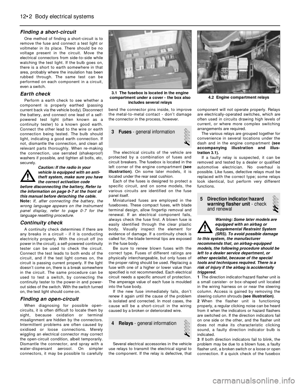
3 Fuses- general information
1
The electrical circuits of the vehicle are
protected by a combination of fuses and
circuit breakers. The fusebox is located in the
left corner of the engine compartment (see
illustration). On some later models, it is
located under the rear seat cushion.
Each of the fuses is designed to protect a
specific circuit, and on some models, the
various circuits are identified on the fuse
panel itself.
Miniaturised fuses are employed in the
fuseboxes. These compact fuses, with blade
terminal design, allow fingertip removal and
renewal. If an electrical component fails,
always check the fuse first. A blown fuse is
easily identified through the clear plastic
body. Visually inspect the element for
evidence of damage. If a continuity check is
called for, the blade terminal tips are exposed
in the fuse body.
Be sure to renew blown fuses with the
correct type. Fuses of different ratings are
physically interchangeable, but only fuses of
the proper rating should be used. Replacing a
fuse with one of a higher or lower value than
specified is not recommended. Each electrical
circuit needs a specific amount of protection.
The amperage value of each fuse is moulded
into the fuse body.
If the new fuse immediately fails, don’t
renew it again until the cause of the problem
is isolated and corrected. In most cases, the
cause will be a short-circuit in the wiring
caused by a broken or deteriorated wire.
4 Relays- general information
1
Several electrical accessories in the vehicle
use relays to transmit the electrical signal to
the component. If the relay is defective, thatcomponent will not operate properly. Relays
are electrically-operated switches, which are
often used in circuits drawing high levels of
current, or where more complex switching
arrangements are required.
The various relays are grouped together for
convenience in several locations under the
dash and in the engine compartment (see
accompanying illustration and illus-
tration 3.1).
If a faulty relay is suspected, it can be
removed and tested by a dealer or qualified
automotive electrician. No overhaul is
possible. Like fuses, defective relays must be
replaced with the correct type; some relays
look identical, but perform very different
functions.
5 Direction indicator/hazard
warning flasher unit- check
and renewal
2
Warning: Some later models are
equipped with an airbag or
Supplemental Restraint System
(SRS). To avoid possible damage
to this system, the manufacturer
recommends that, on airbag-equipped
models, the following procedure should be
left to a dealer service department, or
other specialist, because of the special
tools and techniques required. There is a
risk of injury if the airbag is accidentally
triggered.
1The direction indicator/hazard flasher unit is
a small canister- or box-shaped unit located
in the wiring harness on or near the steering
column. Access is gained by removing the
steering column shrouds (see illustration).
2When the flasher unit is functioning
properly, a regular clicking noise can be heard
from it when the indicators or hazard flashers
are switched on. If the direction indicators fail
on one side or the other, and the flasher unit
does not make its characteristic clicking
sound, a faulty direction indicator bulb is
indicated.
3If both direction indicators fail to blink, the
problem may be due to a blown fuse, a faulty
flasher unit, a broken switch or a loose or open
connection. If a quick check of the fusebox
12•2 Body electrical systems
4.2 Engine compartment relays3.1 The fusebox is located in the engine
compartment under a cover - the box also
includes several relays
Page 172 of 228
8 Radio- removal and refitting
1
Caution: If the radio in your
vehicle is equipped with an anti-
theft system, make sure you have
the correct activation code
before disconnecting the battery, Refer to
the information on page 0-7 at the front of
this manual before detaching the cable.
Note: If, after connecting the battery, the
wrong language appears on the instrument
panel display, refer to page 0-7 for the
language resetting procedure.
Removal
1Disconnect the battery negative cable.
2The radios on most models are held in place
by internal clips which are usually located at
the sides or corners of the unit faceplate.
Removal requires a special tool which is
inserted into the holes to release the clips so
the radio can be pulled out. These tools can be
fabricated from heavy wire, or are available
from your dealer or a car audio specialist. On
anti-theft radios, the clips are moved in and
out by internal screws which require another
type of tool. Insert the tool into the holes until
the clips release, then withdraw the radio from
the dash panel. Disconnect the wiring from the
radio and remove it.3On some models, the radio is held in place
by screws located beneath the faceplate. The
control knobs must be pulled off before the
faceplate can be withdrawn.
Refitting
4Refitting is the reverse of removal.
9 Aerial- removal and refitting
1
Caution: If the radio in your
vehicle is equipped with an anti-
theft system, make sure you have
the correct activation code
before disconnecting the battery, Refer to
the information on page 0-7 at the front of
this manual before detaching the cable.
Note: If, after connecting the battery, the
wrong language appears on the instrument
panel display, refer to page 0-7 for the
language resetting procedure.
Removal
1Disconnect the battery negative cable.
2Use circlip pliers to unscrew the aerial
mounting nut.
3Open the boot lid/tailgate and remove the
left side trim panel. On some models, the jack
and tail light cluster cover will have to be
removed first.
4Unplug the aerial power and radio lead
connectors (as applicable), remove the
retaining bolts, and remove the aerial and
motor assembly.
Refitting
5Refitting is the reverse of removal.
10 Instrument cluster-
removal and refitting
2
Caution: The instrument cluster
and components are very
susceptible to damage from
static electricity. Make sure you
are earthed and have dischargedany static electricity (by touching an object
such as a metal water pipe) before
touching the cluster or components.
Caution: If the radio in your
vehicle is equipped with an anti-
theft system, make sure you have
the correct activation code
before disconnecting the battery, Refer to
the information on page 0-7 at the front of
this manual before detaching the cable.
Note: If, after connecting the battery, the
wrong language appears on the instrument
panel display, refer to page 0-7 for the
language resetting procedure.
Removal
1Disconnect the battery negative cable.
2As necessary, remove the steering column
shrouds and lower trim panel (see Chap-
ter 11).
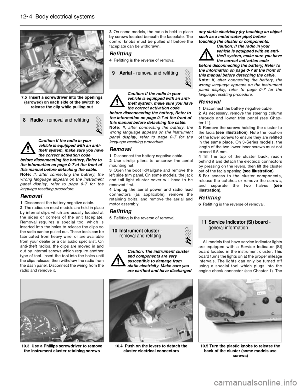
3Remove the screws holding the cluster to
the facia (see illustration). Note the location
of the lower screws to ensure they are refitted
in the same place. On 3-Series models, the
length of the two lower inner screws must not
exceed 9.5 mm.
4Tilt the top of the cluster back, reach
behind it and detach the electrical connectors
by pressing on the levers, then lift the cluster
out of the facia opening (see illustration).
5For access to the cluster components,
release the catches or remove the screws,
and separate the two halves (see
illustration).
Refitting
6Refitting is the reverse of removal.
11 Service Indicator (SI) board-
general information
All models that have service indicator lights
are equipped with a Service Indicator (SI)
board located in the instrument cluster. This
board turns the lights on at the proper mileage
intervals. The lights can only be turned off
using a special tool which plugs into the
engine check connector (see Chapter 1). The
12•4 Body electrical systems
10.5 Turn the plastic knobs to release the
back of the cluster (some models use
screws)10.4 Push on the levers to detach the
cluster electrical connectors10.3 Use a Phillips screwdriver to remove
the instrument cluster retaining screws
7.5 Insert a screwdriver into the openings
(arrowed) on each side of the switch to
release the clip while pulling out
Page 176 of 228
12Refitting is a reversal of removal. When
fitting the motor, if necessary plug in the
connector and run the motor briefly until it is
in the “neutral” (wiper parked) position.
17 Heated rear window-
check and repair
2
1The heated rear window consists of a
number of horizontal elements on the glass
surface.
2Small breaks in the element can be repaired
without removing the rear window.
Check
3Switch on the ignition and the heated rear
window.
4Place the positive lead of a voltmeter to the
heater element nearest to the incoming power
source.
5Wrap a piece of aluminium foil around the
negative lead of the voltmeter on the positive
side of the suspected broken element, and
slide it slowly towards the negative side.
Watch the voltmeter needle - when it moves
from zero, you have located the break.
Repair
6Repair the break in the line using a repair kit
recommended specifically for this purpose,
such as BMW repair kit No. 81 22 9 (or
equivalent). Included in this kit is plastic
conductive epoxy. The following paragraphs
give general instructions for this type of repair;
follow the instructions supplied with the repair
kit if they are different.
7Prior to repairing a break, switch off the
circuit and allow it to cool down for a few
minutes.
8Lightly buff the element area with fine steel
wool, then clean it thoroughly.
9Use masking tape to mask off the area of
repair, leaving a slit to which the epoxy can be
applied.
10Mix the epoxy thoroughly, according to
the instructions on the package.
11Apply the epoxy material to the slit in the
masking tape, overlapping the undamaged
area about 20 mm on each end.12Allow the repair to cure for 24 hours
before removing the tape and using the
heated rear window.
18 Supplemental Restraint
System (SRS)- general
information
Later models are equipped with a
Supplemental Restraint System (SRS),
incorporating an airbag. This system is
designed to protect the driver from serious
injury in the event of a head-on or frontal
collision. It consists of an airbag module in the
centre of the steering wheel, two crash
sensors mounted on the front inner wing
panels, and a crash safety switch located
inside the passenger compartment.
The airbag module contains a housing
incorporating the airbag and the inflator units.
The inflator assembly is mounted on the back
of the housing over a hole through which gas
is expelled, inflating the bag almost instanta-
neously when an electrical signal is sent from
the system. This signal is carried by a wire
which is specially wound with several turns,
so the signal will be transmitted regardless of
the steering wheel position.
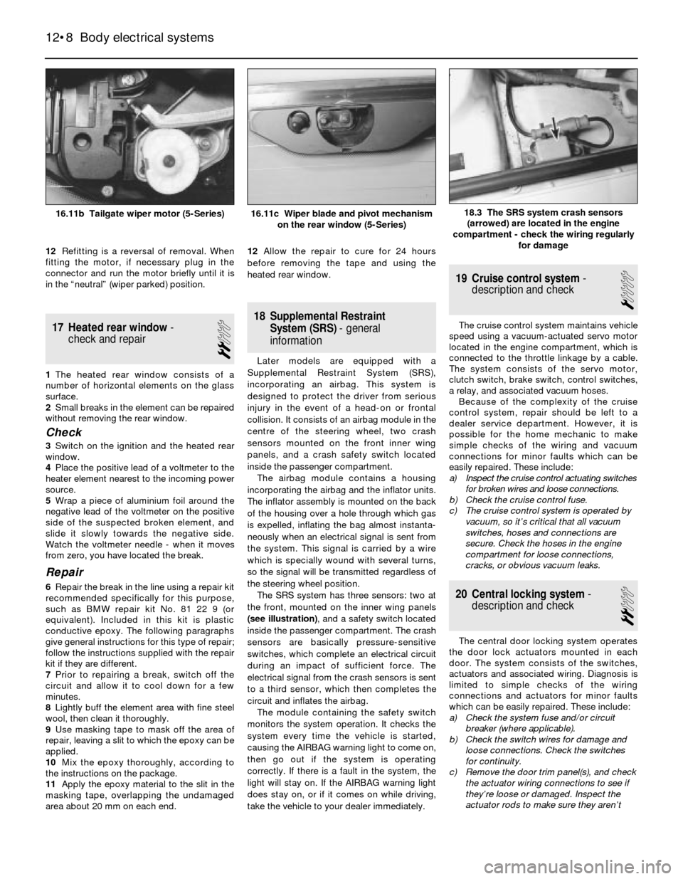
The SRS system has three sensors: two at
the front, mounted on the inner wing panels
(see illustration), and a safety switch located
inside the passenger compartment. The crash
sensors are basically pressure-sensitive
switches, which complete an electrical circuit
during an impact of sufficient force. The
electrical signal from the crash sensors is sent
to a third sensor, which then completes the
circuit and inflates the airbag.
The module containing the safety switch
monitors the system operation. It checks the
system every time the vehicle is started,
causing the AIRBAG warning light to come on,
then go out if the system is operating
correctly. If there is a fault in the system, the
light will stay on. If the AIRBAG warning light
does stay on, or if it comes on while driving,
take the vehicle to your dealer immediately.
19 Cruise control system-
description and check
1
The cruise control system maintains vehicle
speed using a vacuum-actuated servo motor
located in the engine compartment, which is
connected to the throttle linkage by a cable.
The system consists of the servo motor,
clutch switch, brake switch, control switches,
a relay, and associated vacuum hoses.
Because of the complexity of the cruise
control system, repair should be left to a
dealer service department. However, it is
possible for the home mechanic to make
simple checks of the wiring and vacuum
connections for minor faults which can be
easily repaired. These include:
a) Inspect the cruise control actuating switches
for broken wires and loose connections.
b) Check the cruise control fuse.
c) The cruise control system is operated by
vacuum, so it’s critical that all vacuum
switches, hoses and connections are
secure. Check the hoses in the engine
compartment for loose connections,
cracks, or obvious vacuum leaks.
20 Central locking system-
description and check
2
The central door locking system operates
the door lock actuators mounted in each
door. The system consists of the switches,
actuators and associated wiring. Diagnosis is
limited to simple checks of the wiring
connections and actuators for minor faults
which can be easily repaired. These include:
a) Check the system fuse and/or circuit
breaker (where applicable).
b) Check the switch wires for damage and
loose connections. Check the switches
for continuity.
c) Remove the door trim panel(s), and check
the actuator wiring connections to see if
they’re loose or damaged. Inspect the
actuator rods to make sure they aren’t
12•8 Body electrical systems
18.3 The SRS system crash sensors
(arrowed) are located in the engine
compartment - check the wiring regularly
for damage16.11b Tailgate wiper motor (5-Series)16.11c Wiper blade and pivot mechanism
on the rear window (5-Series)
Page 202 of 228
REF•1
REF
MOT Test Checks
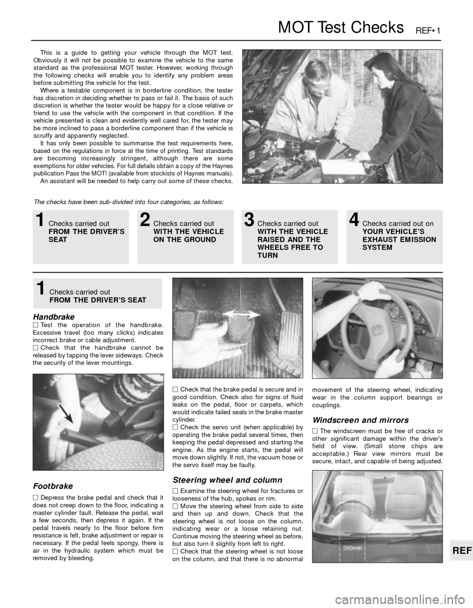
This is a guide to getting your vehicle through the MOT test.
Obviously it will not be possible to examine the vehicle to the same
standard as the professional MOT tester. However, working through
the following checks will enable you to identify any problem areas
before submitting the vehicle for the test.
Where a testable component is in borderline condition, the tester
has discretion in deciding whether to pass or fail it. The basis of such
discretion is whether the tester would be happy for a close relative or
friend to use the vehicle with the component in that condition. If the
vehicle presented is clean and evidently well cared for, the tester may
be more inclined to pass a borderline component than if the vehicle is
scruffy and apparently neglected.
It has only been possible to summarise the test requirements here,
based on the regulations in force at the time of printing. Test standards
are becoming increasingly stringent, although there are some
exemptions for older vehicles. For full details obtain a copy of the Haynes
publication Pass the MOT! (available from stockists of Haynes manuals).
An assistant will be needed to help carry out some of these checks.
The checks have been sub-divided into four categories, as follows:
HandbrakeMTest the operation of the handbrake.
Excessive travel (too many clicks) indicates
incorrect brake or cable adjustment.
MCheck that the handbrake cannot be
released by tapping the lever sideways. Check
the security of the lever mountings.
Footbrake
MDepress the brake pedal and check that it
does not creep down to the floor, indicating a
master cylinder fault. Release the pedal, wait
a few seconds, then depress it again. If the
pedal travels nearly to the floor before firm
resistance is felt, brake adjustment or repair is
necessary. If the pedal feels spongy, there is
air in the hydraulic system which must be
removed by bleeding.MCheck that the brake pedal is secure and in
good condition. Check also for signs of fluid
leaks on the pedal, floor or carpets, which
would indicate failed seals in the brake master
cylinder.
MCheck the servo unit (when applicable) by
operating the brake pedal several times, then
keeping the pedal depressed and starting the
engine. As the engine starts, the pedal will
move down slightly. If not, the vacuum hose or
the servo itself may be faulty.
Steering wheel and column
MExamine the steering wheel for fractures or
looseness of the hub, spokes or rim.
MMove the steering wheel from side to side
and then up and down. Check that the
steering wheel is not loose on the column,
indicating wear or a loose retaining nut.
Continue moving the steering wheel as before,
but also turn it slightly from left to right.
MCheck that the steering wheel is not loose
on the column, and that there is no abnormalmovement of the steering wheel, indicating
wear in the column support bearings or
couplings.
Windscreen and mirrors
MThe windscreen must be free of cracks or
other significant damage within the driver’s
field of view. (Small stone chips are
acceptable.) Rear view mirrors must be
secure, intact, and capable of being adjusted.
1Checks carried out
FROM THE DRIVER’S SEAT
1Checks carried out
FROM THE DRIVER’S
SEAT2Checks carried out
WITH THE VEHICLE
ON THE GROUND3Checks carried out
WITH THE VEHICLE
RAISED AND THE
WHEELS FREE TO
TURN4Checks carried out on
YOUR VEHICLE’S
EXHAUST EMISSION
SYSTEM
Page 204 of 228
REF•3
REF
MOT Test Checks
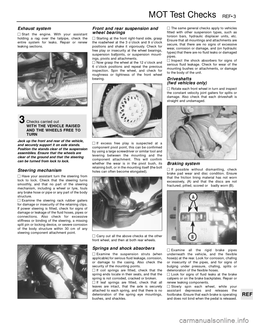
Exhaust system
MStart the engine. With your assistant
holding a rag over the tailpipe, check the
entire system for leaks. Repair or renew
leaking sections.
Jack up the front and rear of the vehicle,
and securely support it on axle stands.
Position the stands clear of the suspension
assemblies. Ensure that the wheels are
clear of the ground and that the steering
can be turned from lock to lock.
Steering mechanism
MHave your assistant turn the steering from
lock to lock. Check that the steering turns
smoothly, and that no part of the steering
mechanism, including a wheel or tyre, fouls
any brake hose or pipe or any part of the body
structure.
MExamine the steering rack rubber gaiters
for damage or insecurity of the retaining clips.
If power steering is fitted, check for signs of
damage or leakage of the fluid hoses, pipes or
connections. Also check for excessive
stiffness or binding of the steering, a missing
split pin or locking device, or severe corrosion
of the body structure within 30 cm of any
steering component attachment point.
Front and rear suspension and
wheel bearings
MStarting at the front right-hand side, grasp
the roadwheel at the 3 o’clock and 9 o’clock
positions and shake it vigorously. Check for
free play or insecurity at the wheel bearings,
suspension balljoints, or suspension mount-
ings, pivots and attachments.
MNow grasp the wheel at the 12 o’clock and
6 o’clock positions and repeat the previous
inspection. Spin the wheel, and check for
roughness or tightness of the front wheel
bearing.
MIf excess free play is suspected at a
component pivot point, this can be confirmed
by using a large screwdriver or similar tool and
levering between the mounting and the
component attachment. This will confirm
whether the wear is in the pivot bush, its
retaining bolt, or in the mounting itself (the bolt
holes can often become elongated).
MCarry out all the above checks at the other
front wheel, and then at both rear wheels.
Springs and shock absorbers
MExamine the suspension struts (when
applicable) for serious fluid leakage, corrosion,
or damage to the casing. Also check the
security of the mounting points.
MIf coil springs are fitted, check that the
spring ends locate in their seats, and that the
spring is not corroded, cracked or broken.
MIf leaf springs are fitted, check that all
leaves are intact, that the axle is securely
attached to each spring, and that there is no
deterioration of the spring eye mountings,
bushes, and shackles.MThe same general checks apply to vehicles
fitted with other suspension types, such as
torsion bars, hydraulic displacer units, etc.
Ensure that all mountings and attachments are
secure, that there are no signs of excessive
wear, corrosion or damage, and (on hydraulic
types) that there are no fluid leaks or damaged
pipes.
MInspect the shock absorbers for signs of
serious fluid leakage. Check for wear of the
mounting bushes or attachments, or damage
to the body of the unit.
Driveshafts
(fwd vehicles only)
MRotate each front wheel in turn and inspect
the constant velocity joint gaiters for splits or
damage. Also check that each driveshaft is
straight and undamaged.
Braking system
MIf possible without dismantling, check
brake pad wear and disc condition. Ensure
that the friction lining material has not worn
excessively, (A) and that the discs are not
fractured, pitted, scored or badly worn (B).
MExamine all the rigid brake pipes
underneath the vehicle, and the flexible
hose(s) at the rear. Look for corrosion, chafing
or insecurity of the pipes, and for signs of
bulging under pressure, chafing, splits or
deterioration of the flexible hoses.
MLook for signs of fluid leaks at the brake
calipers or on the brake backplates. Repair or
renew leaking components.
MSlowly spin each wheel, while your
assistant depresses and releases the
footbrake. Ensure that each brake is operating
and does not bind when the pedal is released.
3Checks carried out
WITH THE VEHICLE RAISED
AND THE WHEELS FREE TO
TURN
Page 205 of 228
REF•4MOT Test Checks
MExamine the handbrake mechanism,
checking for frayed or broken cables,
excessive corrosion, or wear or insecurity of
the linkage. Check that the mechanism works
on each relevant wheel, and releases fully,
without binding.
MIt is not possible to test brake efficiency
without special equipment, but a road test can
be carried out later to check that the vehicle
pulls up in a straight line.
Fuel and exhaust systems
MInspect the fuel tank (including the filler
cap), fuel pipes, hoses and unions. All
components must be secure and free from
leaks.
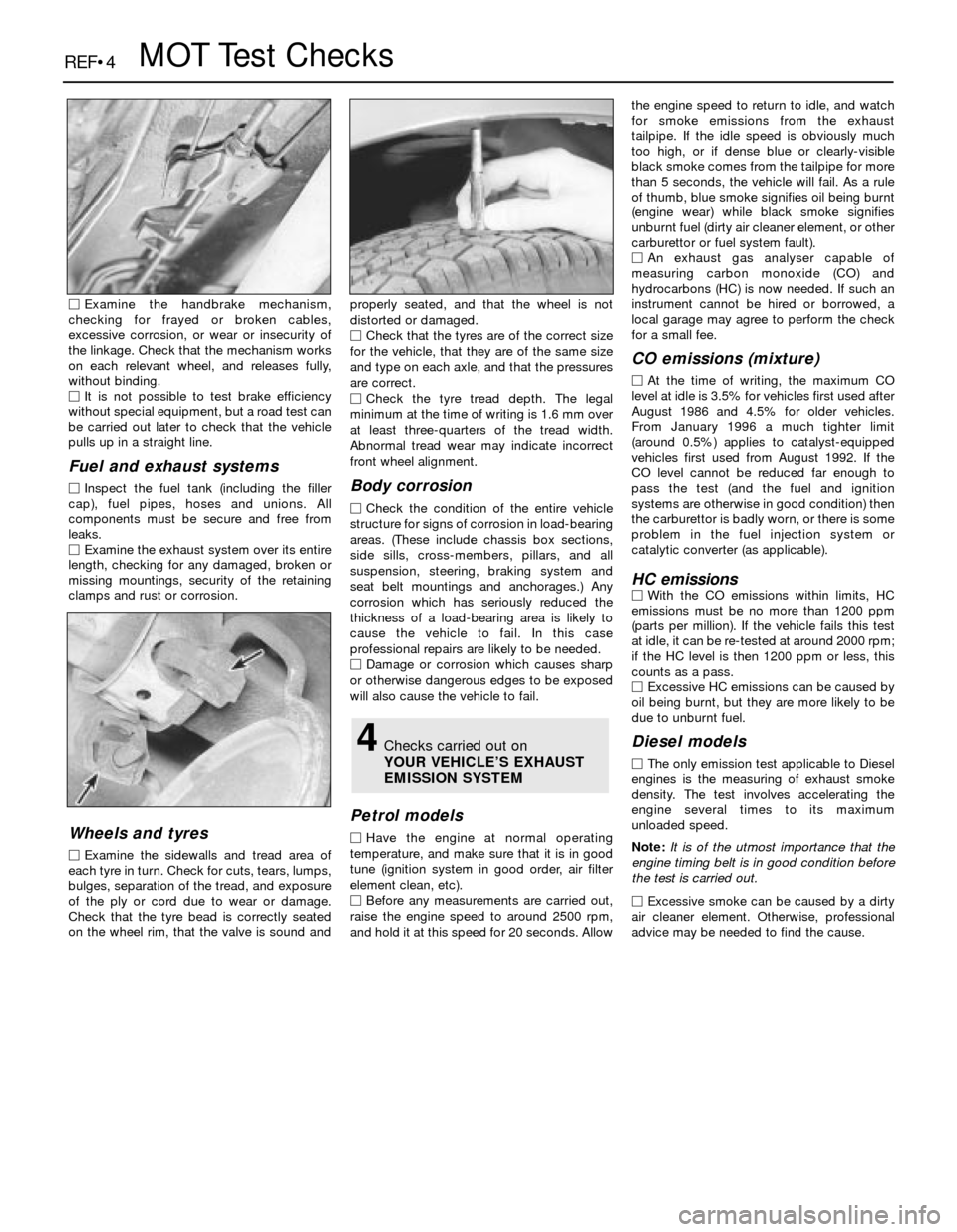
MExamine the exhaust system over its entire
length, checking for any damaged, broken or
missing mountings, security of the retaining
clamps and rust or corrosion.
Wheels and tyres
MExamine the sidewalls and tread area of
each tyre in turn. Check for cuts, tears, lumps,
bulges, separation of the tread, and exposure
of the ply or cord due to wear or damage.
Check that the tyre bead is correctly seated
on the wheel rim, that the valve is sound andproperly seated, and that the wheel is not
distorted or damaged.
MCheck that the tyres are of the correct size
for the vehicle, that they are of the same size
and type on each axle, and that the pressures
are correct.
MCheck the tyre tread depth. The legal
minimum at the time of writing is 1.6 mm over
at least three-quarters of the tread width.
Abnormal tread wear may indicate incorrect
front wheel alignment.
Body corrosion
MCheck the condition of the entire vehicle
structure for signs of corrosion in load-bearing
areas. (These include chassis box sections,
side sills, cross-members, pillars, and all
suspension, steering, braking system and
seat belt mountings and anchorages.) Any
corrosion which has seriously reduced the
thickness of a load-bearing area is likely to
cause the vehicle to fail. In this case
professional repairs are likely to be needed.
MDamage or corrosion which causes sharp
or otherwise dangerous edges to be exposed
will also cause the vehicle to fail.
Petrol models
MHave the engine at normal operating
temperature, and make sure that it is in good
tune (ignition system in good order, air filter
element clean, etc).
MBefore any measurements are carried out,
raise the engine speed to around 2500 rpm,
and hold it at this speed for 20 seconds. Allowthe engine speed to return to idle, and watch
for smoke emissions from the exhaust
tailpipe. If the idle speed is obviously much
too high, or if dense blue or clearly-visible
black smoke comes from the tailpipe for more
than 5 seconds, the vehicle will fail. As a rule
of thumb, blue smoke signifies oil being burnt
(engine wear) while black smoke signifies
unburnt fuel (dirty air cleaner element, or other
carburettor or fuel system fault).
MAn exhaust gas analyser capable of
measuring carbon monoxide (CO) and
hydrocarbons (HC) is now needed. If such an
instrument cannot be hired or borrowed, a
local garage may agree to perform the check
for a small fee.
CO emissions (mixture)
MAt the time of writing, the maximum CO
level at idle is 3.5% for vehicles first used after
August 1986 and 4.5% for older vehicles.
From January 1996 a much tighter limit
(around 0.5%) applies to catalyst-equipped
vehicles first used from August 1992. If the
CO level cannot be reduced far enough to
pass the test (and the fuel and ignition
systems are otherwise in good condition) then
the carburettor is badly worn, or there is some
problem in the fuel injection system or
catalytic converter (as applicable).
HC emissionsMWith the CO emissions within limits, HC
emissions must be no more than 1200 ppm
(parts per million). If the vehicle fails this test
at idle, it can be re-tested at around 2000 rpm;
if the HC level is then 1200 ppm or less, this
counts as a pass.
MExcessive HC emissions can be caused by
oil being burnt, but they are more likely to be
due to unburnt fuel.
Diesel models
MThe only emission test applicable to Diesel
engines is the measuring of exhaust smoke
density. The test involves accelerating the
engine several times to its maximum
unloaded speed.
Note: It is of the utmost importance that the
engine timing belt is in good condition before
the test is carried out.
M
Excessive smoke can be caused by a dirty
air cleaner element. Otherwise, professional
advice may be needed to find the cause.
4Checks carried out on
YOUR VEHICLE’S EXHAUST
EMISSION SYSTEM