ECO BMW 3 SERIES 1983 E30 Repair Manual
[x] Cancel search | Manufacturer: BMW, Model Year: 1983, Model line: 3 SERIES, Model: BMW 3 SERIES 1983 E30Pages: 228, PDF Size: 7.04 MB
Page 99 of 228
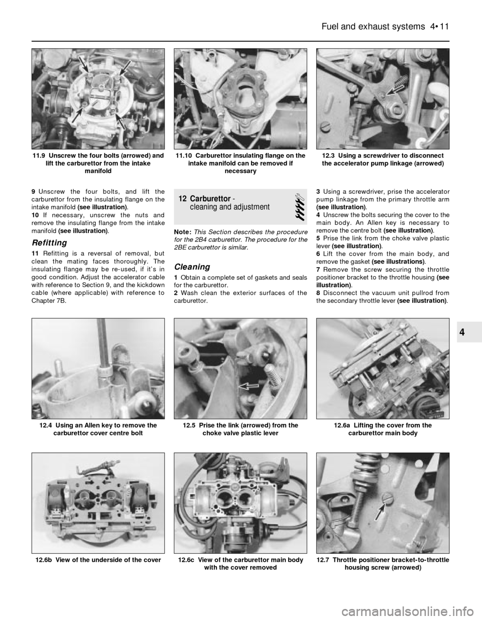
9Unscrew the four bolts, and lift the
carburettor from the insulating flange on the
intake manifold (see illustration).
10If necessary, unscrew the nuts and
remove the insulating flange from the intake
manifold (see illustration).
Refitting
11Refitting is a reversal of removal, but
clean the mating faces thoroughly. The
insulating flange may be re-used, if it’s in
good condition. Adjust the accelerator cable
with reference to Section 9, and the kickdown
cable (where applicable) with reference to
Chapter 7B.
12 Carburettor-
cleaning and adjustment
4
Note:This Section describes the procedure
for the 2B4 carburettor. The procedure for the
2BE carburettor is similar.
Cleaning
1Obtain a complete set of gaskets and seals
for the carburettor.
2Wash clean the exterior surfaces of the
carburettor.3Using a screwdriver, prise the accelerator
pump linkage from the primary throttle arm
(see illustration).
4Unscrew the bolts securing the cover to the
main body. An Allen key is necessary to
remove the centre bolt (see illustration).
5Prise the link from the choke valve plastic
lever (see illustration).
6Lift the cover from the main body, and
remove the gasket (see illustrations).
7Remove the screw securing the throttle
positioner bracket to the throttle housing (see
illustration).
8Disconnect the vacuum unit pullrod from
the secondary throttle lever (see illustration).
Fuel and exhaust systems 4•11
12.3 Using a screwdriver to disconnect
the accelerator pump linkage (arrowed)11.10 Carburettor insulating flange on the
intake manifold can be removed if
necessary11.9 Unscrew the four bolts (arrowed) and
lift the carburettor from the intake
manifold
12.7 Throttle positioner bracket-to-throttle
housing screw (arrowed)12.6c View of the carburettor main body
with the cover removed12.6b View of the underside of the cover
12.6a Lifting the cover from the
carburettor main body12.5 Prise the link (arrowed) from the
choke valve plastic lever12.4 Using an Allen key to remove the
carburettor cover centre bolt
4
Page 100 of 228
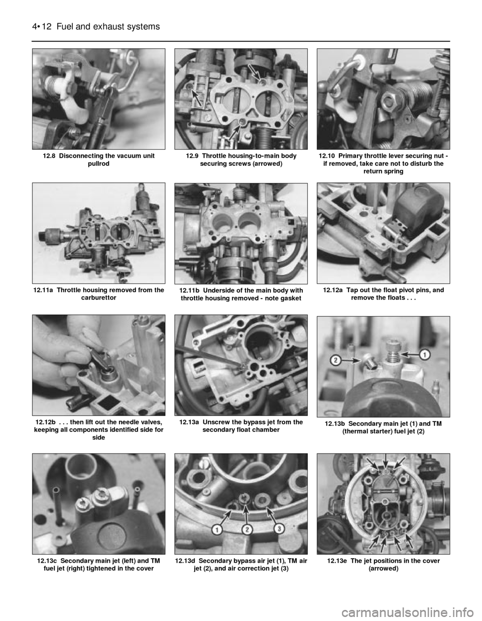
12.13e The jet positions in the cover
(arrowed)
4•12 Fuel and exhaust systems
12.13d Secondary bypass air jet (1), TM air
jet (2), and air correction jet (3)12.13c Secondary main jet (left) and TM
fuel jet (right) tightened in the cover
12.13b Secondary main jet (1) and TM
(thermal starter) fuel jet (2)12.13a Unscrew the bypass jet from the
secondary float chamber12.12b . . . then lift out the needle valves,
keeping all components identified side for
side
12.12a Tap out the float pivot pins, and
remove the floats . . .12.11a Throttle housing removed from the
carburettor12.11b Underside of the main body with
throttle housing removed - note gasket
12.10 Primary throttle lever securing nut -
if removed, take care not to disturb the
return spring12.9 Throttle housing-to-main body
securing screws (arrowed)12.8 Disconnecting the vacuum unit
pullrod
Page 101 of 228
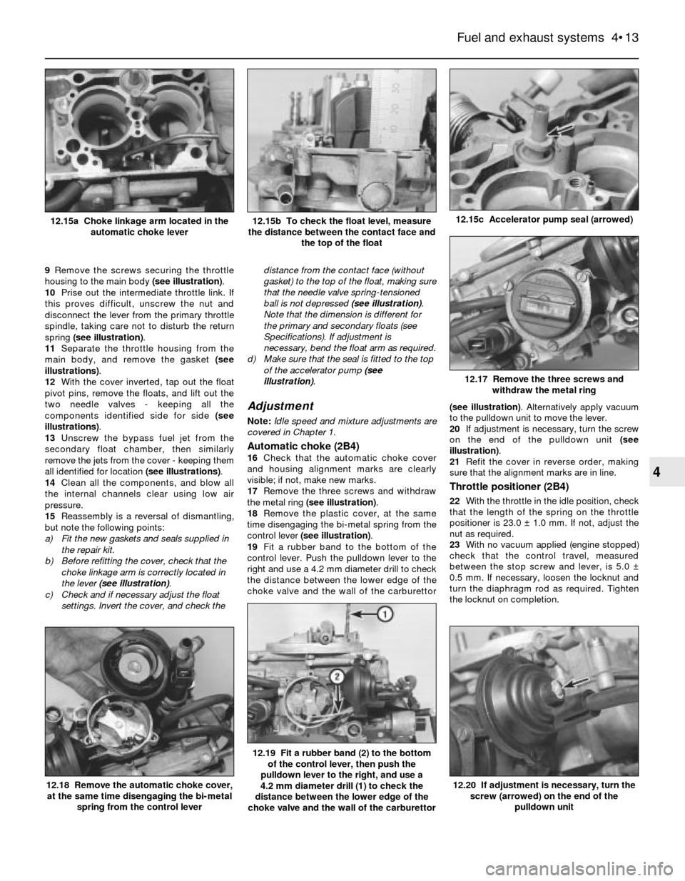
9Remove the screws securing the throttle
housing to the main body (see illustration).
10Prise out the intermediate throttle link. If
this proves difficult, unscrew the nut and
disconnect the lever from the primary throttle
spindle, taking care not to disturb the return
spring (see illustration).
11Separate the throttle housing from the
main body, and remove the gasket (see
illustrations).
12With the cover inverted, tap out the float
pivot pins, remove the floats, and lift out the
two needle valves - keeping all the
components identified side for side (see
illustrations).
13Unscrew the bypass fuel jet from the
secondary float chamber, then similarly
remove the jets from the cover - keeping them
all identified for location (see illustrations).
14Clean all the components, and blow all
the internal channels clear using low air
pressure.
15Reassembly is a reversal of dismantling,
but note the following points:
a) Fit the new gaskets and seals supplied in
the repair kit.
b) Before refitting the cover, check that the
choke linkage arm is correctly located in
the lever (see illustration).
c) Check and if necessary adjust the float
settings. Invert the cover, and check thedistance from the contact face (without
gasket) to the top of the float, making sure
that the needle valve spring-tensioned
ball is not depressed (see illustration).
Note that the dimension is different for
the primary and secondary floats (see
Specifications). If adjustment is
necessary, bend the float arm as required.
d) Make sure that the seal is fitted to the top
of the accelerator pump (see
illustration).
Adjustment
Note:Idle speed and mixture adjustments are
covered in Chapter 1.
Automatic choke (2B4)16Check that the automatic choke cover
and housing alignment marks are clearly
visible; if not, make new marks.
17Remove the three screws and withdraw
the metal ring (see illustration).
18Remove the plastic cover, at the same
time disengaging the bi-metal spring from the
control lever (see illustration).
19Fit a rubber band to the bottom of the
control lever. Push the pulldown lever to the
right and use a 4.2 mm diameter drill to check
the distance between the lower edge of the
choke valve and the wall of the carburettor(see illustration). Alternatively apply vacuum
to the pulldown unit to move the lever.
20If adjustment is necessary, turn the screw
on the end of the pulldown unit (see
illustration).
21Refit the cover in reverse order, making
sure that the alignment marks are in line.
Throttle positioner (2B4)
22With the throttle in the idle position, check
that the length of the spring on the throttle
positioner is 23.0 ± 1.0 mm. If not, adjust the
nut as required.
23With no vacuum applied (engine stopped)
check that the control travel, measured
between the stop screw and lever, is 5.0 ±
0.5 mm. If necessary, loosen the locknut and
turn the diaphragm rod as required. Tighten
the locknut on completion.
Fuel and exhaust systems 4•13
12.15b To check the float level, measure
the distance between the contact face and
the top of the float12.15a Choke linkage arm located in the
automatic choke lever
12.20 If adjustment is necessary, turn the
screw (arrowed) on the end of the
pulldown unit
12.19 Fit a rubber band (2) to the bottom
of the control lever, then push the
pulldown lever to the right, and use a
4.2 mm diameter drill (1) to check the
distance between the lower edge of the
choke valve and the wall of the carburettor
12.17 Remove the three screws and
withdraw the metal ring
12.15c Accelerator pump seal (arrowed)
12.18 Remove the automatic choke cover,
at the same time disengaging the bi-metal
spring from the control lever
4
Page 102 of 228
Throttle positioner (2BE)
24Special tools are required to carry out a
comprehensive adjustment on the 2BE
carburettor. This work should therefore be left
to a BMW dealer.
13 Fuel injection -
general information
The fuel injection system is composed of
three basic sub-systems: fuel system, air
intake system and electronic control system.
Fuel system
An electric fuel pump, located inside the
fuel tank or beside the fuel tank, supplies fuel
under constant pressure to the fuel rail, which
distributes fuel evenly to all injectors. From
the fuel rail, fuel is injected into the intake
ports, just above the intake valves, by the fuel
injectors. The amount of fuel supplied by the
injectors is precisely controlled by an
Electronic Control Unit (ECU). An additional
injector, known as the cold start injector (L-
Jetronic and early Motronic systems only),
supplies extra fuel into the intake manifold for
starting. A pressure regulator controls system
pressure in relation to intake manifold
vacuum. A fuel filter between the fuel pump
and the fuel rail filters the fuel, to protect the
components of the system.
Air intake system
The air intake system consists of an air filter
housing, an airflow meter, a throttle body, the
intake manifold, and the associated ducting.
The airflow meter is an information-gathering
device for the ECU. These models are
equipped with the vane-type airflow meter. A
potentiometer measures intake airflow, and a
temperature sensor measures intake air
temperature. This information helps the ECU
determine the amount of fuel to be injected by
the injectors (injection duration). The throttle
plate inside the throttle body is controlled by
the driver. As the throttle plate opens, the
amount of air that can pass through the
system increases, so the potentiometer opens
further and the ECU signals the injectors to
increase the amount of fuel delivered to the
intake ports.
Electronic control system
The computer control system controls the
fuel system and other systems by means of
an Electronic Control Unit (ECU). The ECU
receives signals from a number of information
sensors which monitor such variables as
intake air volume, intake air temperature,
coolant temperature, engine rpm,
acceleration/deceleration, and exhaust
oxygen content. These signals help the ECU
determine the injection duration necessary for
the optimum air/fuel ratio. These sensors and
their corresponding ECU-controlled outputactuators are located throughout the engine
compartment. For further information
regarding the ECU and its relationship to the
engine electrical systems and ignition system,
refer to Chapters 5 and 6.
Either an L-Jetronic system or a Motronic
system is fitted. Later models have an
updated version of the original Motronic
system.
14 Fuel injection systems
L-Jetronic fuel injection system
The Bosch L-Jetronic fuel injection system
is used on most 3-Series models up to 1987,
and on most E28 (“old-shape”) 5-Series
models. It is an electronically-controlled fuel
injection system that utilises one solenoid-
operated fuel injector per cylinder. The system
is governed by an Electronic Control Unit
(ECU) which processes information sent by
various sensors, and in turn precisely
meters the fuel to the cylinders by
adjusting the amount of time that the injectors
are open.
An electric fuel pump delivers fuel under
high pressure to the injectors, through the fuel
feed line and an in-line filter. A pressure
regulator keeps fuel available at an optimum
pressure, allowing pressure to rise or fall
depending on engine speed and load. Any
excess fuel is returned to the fuel tank by a
separate line.
A sensor in the air intake duct constantly
measures the mass of the incoming air, and
the ECU adjusts the fuel mixture to provide an
optimum air/fuel ratio.
Other components incorporated in the
system are the throttle valve (which controls
airflow to the engine), the coolant temperature
sensor, the throttle position switch, idle
stabiliser valve (which bypasses air around
the throttle plate to control idle speed) and
associated relays and fuses.
Motronic fuel injection system
The Motronic system combines the fuel
control of the L-Jetronic fuel injection system
with the control of ignition timing, idle speed
and emissions into one control unit.
The fuel injection and idle speed control
functions are similar to those used on the L-
Jetronic system described above. For more
information on the Motronic system, see
Chapter 6.
An oxygen sensor is mounted in the
exhaust system on later models with a
catalytic converter. This sensor continually
reads the oxygen content of the exhaust gas.
The information is used by the ECU to adjust
the duration of injection, making it possible to
adjust the fuel mixture for optimum converter
efficiency and minimum emissions.
15 Fuel injection system-
check
2
Warning: Fuel is extremely
flammable, so take extra
precautions when you work on
any part of the fuel system. Don’t
smoke, or allow open flames or bare light
bulbs, near the work area. Don’t work in a
garage where a natural gas-type appliance
(such as a water heater or clothes dryer)
with a pilot light is present. If you spill any
fuel on your skin, rinse it off immediately
with soap and water. When you perform
any kind of work on the fuel system, wear
safety glasses, and have a fire
extinguisher on hand.
1Check the earth wire connections. Check
all wiring harness connectors that are related
to the system. Loose connectors and poor
earths can cause many problems that
resemble more serious malfunctions.
2Make sure the battery is fully charged, as
the control unit and sensors depend on an
accurate supply voltage in order to properly
meter the fuel.
3Check the air filter element - a dirty or
partially-blocked filter will severely impede
performance and economy (see Chapter 1).
4If a blown fuse is found, renew it and see if
it blows again. If it does, search for an earthed
wire in the harness related to the system.
5Check the air intake duct from the airflow
meter to the intake manifold for leaks. Intake
air leaks can cause a variety of problems. Also
check the condition of the vacuum hoses
connected to the intake manifold.
6Remove the air intake duct from the throttle
body, and check for dirt, carbon and other
residue build-up. If it’s dirty, clean it with
carburettor cleaner and a toothbrush.
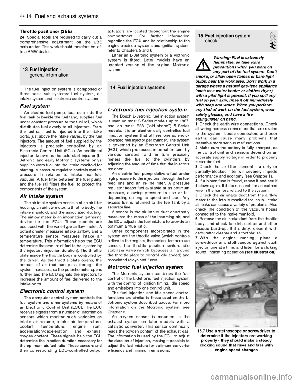
7With the engine running, place a
screwdriver or a stethoscope against each
injector, one at a time, and listen for a clicking
sound, indicating operation (see illustration).
4•14 Fuel and exhaust systems
15.7 Use a stethoscope or screwdriver to
determine if the injectors are working
properly - they should make a steady
clicking sound that rises and falls with
engine speed changes
Page 104 of 228
17 Throttle body- check,
removal and refitting
2
Check
1Detach the air intake duct from the throttle
body (see Section 8) and move the duct out of
the way.
2Have an assistant depress the throttle
pedal while you watch the throttle valve.
Check that the throttle valve moves smoothly
when the throttle is moved from closed (idle
position) to fully-open (wide-open throttle).
3If the throttle valve is not working properly,
renew the throttle body unit.
Warning: Wait until the engine is
completely cool before beginning
this procedure.
Caution: If the radio in your
vehicle is equipped with an anti-
theft system, make sure you
have the correct activation code
before disconnecting the battery. Refer to
the information on page 0-7 at the front of
this manual before detaching the cable.
Note: If, after connecting the battery, the
wrong language appears on the instrument
panel display, refer to page 0-7 for the
language resetting procedure.
Removal and refitting
4Detach the battery negative cable.
5Detach the air intake duct from the throttle
body, and place to one side.
6Detach the accelerator cable from the
throttle body (see Section 9).
7Detach the cruise control cable, if applicable.
8Clearly label all electrical connectors
(throttle position sensor, cold start injector,
idle air stabiliser, etc), then unplug them.
9Clearly label all vacuum hoses, then detach
them.
10Unscrew the radiator or expansion tank
cap to relieve any residual pressure in the
cooling system, then refit it. Clamp shut the
coolant hoses, then loosen the hose clamps
and detach the hoses. Be prepared for some
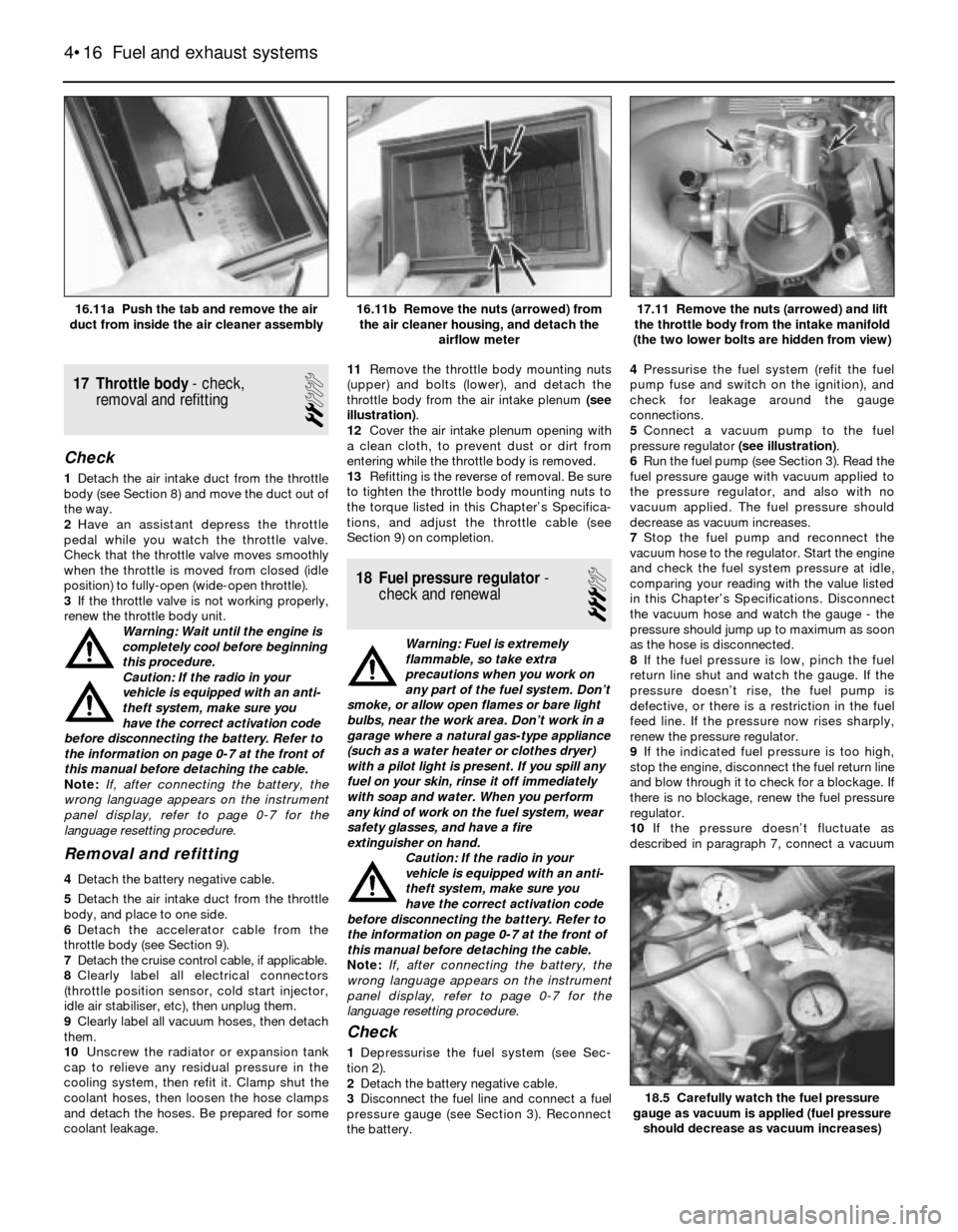
coolant leakage.11Remove the throttle body mounting nuts
(upper) and bolts (lower), and detach the
throttle body from the air intake plenum (see
illustration).
12Cover the air intake plenum opening with
a clean cloth, to prevent dust or dirt from
entering while the throttle body is removed.
13Refitting is the reverse of removal. Be sure
to tighten the throttle body mounting nuts to
the torque listed in this Chapter’s Specifica-
tions, and adjust the throttle cable (see
Section 9) on completion.
18 Fuel pressure regulator-
check and renewal
3
Warning: Fuel is extremely
flammable, so take extra
precautions when you work on
any part of the fuel system. Don’t
smoke, or allow open flames or bare light
bulbs, near the work area. Don’t work in a
garage where a natural gas-type appliance
(such as a water heater or clothes dryer)
with a pilot light is present. If you spill any
fuel on your skin, rinse it off immediately
with soap and water. When you perform
any kind of work on the fuel system, wear
safety glasses, and have a fire
extinguisher on hand.
Caution: If the radio in your
vehicle is equipped with an anti-
theft system, make sure you
have the correct activation code
before disconnecting the battery. Refer to
the information on page 0-7 at the front of
this manual before detaching the cable.
Note: If, after connecting the battery, the
wrong language appears on the instrument
panel display, refer to page 0-7 for the
language resetting procedure.
Check
1Depressurise the fuel system (see Sec-
tion 2).
2Detach the battery negative cable.
3Disconnect the fuel line and connect a fuel
pressure gauge (see Section 3). Reconnect
the battery.4Pressurise the fuel system (refit the fuel
pump fuse and switch on the ignition), and
check for leakage around the gauge
connections.
5Connect a vacuum pump to the fuel
pressure regulator (see illustration).
6Run the fuel pump (see Section 3). Read the
fuel pressure gauge with vacuum applied to
the pressure regulator, and also with no
vacuum applied. The fuel pressure should
decrease as vacuum increases.
7Stop the fuel pump and reconnect the
vacuum hose to the regulator. Start the engine
and check the fuel system pressure at idle,
comparing your reading with the value listed
in this Chapter’s Specifications. Disconnect
the vacuum hose and watch the gauge - the
pressure should jump up to maximum as soon
as the hose is disconnected.
8If the fuel pressure is low, pinch the fuel
return line shut and watch the gauge. If the
pressure doesn’t rise, the fuel pump is
defective, or there is a restriction in the fuel
feed line. If the pressure now rises sharply,
renew the pressure regulator.
9If the indicated fuel pressure is too high,
stop the engine, disconnect the fuel return line
and blow through it to check for a blockage. If
there is no blockage, renew the fuel pressure
regulator.
10If the pressure doesn’t fluctuate as
described in paragraph 7, connect a vacuum
4•16 Fuel and exhaust systems
18.5 Carefully watch the fuel pressure
gauge as vacuum is applied (fuel pressure
should decrease as vacuum increases)
17.11 Remove the nuts (arrowed) and lift
the throttle body from the intake manifold
(the two lower bolts are hidden from view)16.11b Remove the nuts (arrowed) from
the air cleaner housing, and detach the
airflow meter16.11a Push the tab and remove the air
duct from inside the air cleaner assembly
Page 105 of 228
gauge to the pressure regulator vacuum hose,
and check for vacuum (engine idling).
11If there is vacuum present, renew the fuel
pressure regulator.
12If there isn’t any reading on the gauge,
check the hose and its port for a leak or a
restriction.
Renewal
13Depressurise the fuel system (see Sec-
tion 2).
14Detach the battery negative cable.
Caution: If the radio in your
vehicle is equipped with an anti-
theft system, make sure you
have the correct activation code
before disconnecting the battery. Refer to
the information on page 0-7 at the front of
this manual before detaching the cable.
Note: If, after connecting the battery, the
wrong language appears on the instrument
panel display, refer to page 0-7 for the
language resetting procedure.
15Detach the vacuum hose and fuel return
hose from the pressure regulator, then
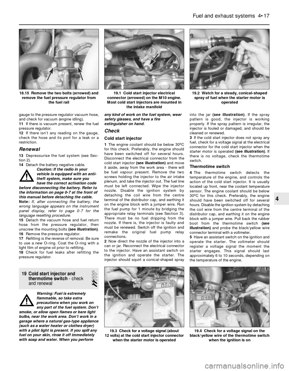
unscrew the mounting bolts (see illustration).
16Remove the pressure regulator.
17Refitting is the reverse of removal. Be sure
to use a new O-ring. Coat the O-ring with a
light film of engine oil prior to refitting.
18Check for fuel leaks after refitting the
pressure regulator.
19 Cold start injector and
thermotime switch- check
and renewal
2
Warning: Fuel is extremely
flammable, so take extra
precautions when you work on
any part of the fuel system. Don’t
smoke, or allow open flames or bare light
bulbs, near the work area. Don’t work in a
garage where a natural gas-type appliance
(such as a water heater or clothes dryer)
with a pilot light is present. If you spill any
fuel on your skin, rinse it off immediately
with soap and water. When you performany kind of work on the fuel system, wear
safety glasses, and have a fire
extinguisher on hand.
Check
Cold start injector
1The engine coolant should be below 30ºC
for this check. Preferably, the engine should
have been switched off for several hours.
Disconnect the electrical connector from the
cold start injector (see illustration)and move
it aside, away from the work area - there will
be fuel vapour present. Remove the two
screws holding the injector to the air intake
plenum, and take the injector out. The fuel line
must be left connected. Wipe the injector
nozzle. Disable the ignition system by
detaching the coil wire from the centre
terminal of the distributor cap, and earthing it
on the engine block with a jumper wire. Run
the fuel pump for 1 minute by bridging the
appropriate relay terminals (see Section 3).
There must be no fuel dripping from the
nozzle. If there is, the injector is faulty and
must be renewed. Switch off the ignition and
remake the original fuel pump relay
connections.
2Now direct the nozzle of the injector into a
can or jar. Reconnect the electrical connector
to the injector. Have an assistant switch on
the ignition and operate the starter. The
injector should squirt a conical-shaped sprayinto the jar (see illustration). If the spray
pattern is good, the injector is working
properly. If the spray pattern is irregular, the
injector is fouled or damaged, and should be
cleaned or renewed.
3If the cold start injector does not spray any
fuel, check for a voltage signal at the electrical
connector for the cold start injector when the
starter motor is operated (see illustration). If
there is no voltage, check the thermotime
switch.
Thermotime switch
4The thermotime switch detects the
temperature of the engine, and controls the
action of the cold start injector. It is usually
located up front, near the coolant temperature
sensor. The engine coolant should be below
30ºC for this check. Preferably, the engine
should have been switched off for several
hours. Disable the ignition system by detaching
the coil wire from the centre terminal of the
distributor cap, and earthing it on the engine
block with a jumper wire. Pull back the rubber
boot from the thermotime switch (see
illustration)and probe the black/yellow wire
connector terminal with a voltmeter.
5Have an assistant switch on the ignition and
operate the starter. The voltmeter should
register a voltage signal the moment the
starter engages. This signal should last
approximately 6 to 10 seconds, depending on
the temperature of the engine.
Fuel and exhaust systems 4•17
19.2 Watch for a steady, conical-shaped
spray of fuel when the starter motor is
operated19.1 Cold start injector electrical
connector (arrowed) on the M10 engine.
Most cold start injectors are mounted in
the intake manifold18.15 Remove the two bolts (arrowed) and
remove the fuel pressure regulator from
the fuel rail
19.4 Check for a voltage signal on the
black/yellow wire of the thermotime switch
when the ignition is on19.3 Check for a voltage signal (about
12 volts) at the cold start injector connector
when the starter motor is operated
4
Page 106 of 228
6If the voltage is correct, unplug the
electrical connector and, using an ohmmeter,
check for continuity between the terminals of
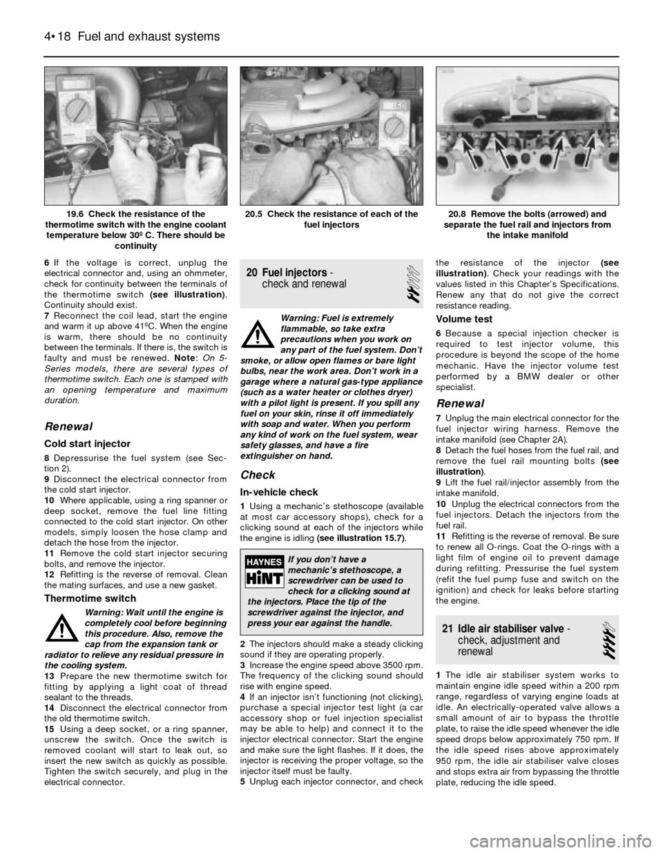
the thermotime switch (see illustration).
Continuity should exist.
7Reconnect the coil lead, start the engine
and warm it up above 41ºC. When the engine
is warm, there should be no continuity
between the terminals. If there is, the switch is
faulty and must be renewed. Note: On 5-
Series models, there are several types of
thermotime switch. Each one is stamped with
an opening temperature and maximum
duration.
Renewal
Cold start injector
8Depressurise the fuel system (see Sec-
tion 2).
9Disconnect the electrical connector from
the cold start injector.
10Where applicable, using a ring spanner or
deep socket, remove the fuel line fitting
connected to the cold start injector. On other
models, simply loosen the hose clamp and
detach the hose from the injector.
11Remove the cold start injector securing
bolts, and remove the injector.
12Refitting is the reverse of removal. Clean
the mating surfaces, and use a new gasket.
Thermotime switch
Warning: Wait until the engine is
completely cool before beginning
this procedure. Also, remove the
cap from the expansion tank or
radiator to relieve any residual pressure in
the cooling system.
13Prepare the new thermotime switch for
fitting by applying a light coat of thread
sealant to the threads.
14Disconnect the electrical connector from
the old thermotime switch.
15Using a deep socket, or a ring spanner,
unscrew the switch. Once the switch is
removed coolant will start to leak out, so
insert the new switch as quickly as possible.
Tighten the switch securely, and plug in the
electrical connector.
20 Fuel injectors-
check and renewal
2
Warning: Fuel is extremely
flammable, so take extra
precautions when you work on
any part of the fuel system. Don’t
smoke, or allow open flames or bare light
bulbs, near the work area. Don’t work in a
garage where a natural gas-type appliance
(such as a water heater or clothes dryer)
with a pilot light is present. If you spill any
fuel on your skin, rinse it off immediately
with soap and water. When you perform
any kind of work on the fuel system, wear
safety glasses, and have a fire
extinguisher on hand.
Check
In-vehicle check
1Using a mechanic’s stethoscope (available
at most car accessory shops), check for a
clicking sound at each of the injectors while
the engine is idling (see illustration 15.7).
2The injectors should make a steady clicking
sound if they are operating properly.
3Increase the engine speed above 3500 rpm.
The frequency of the clicking sound should
rise with engine speed.
4If an injector isn’t functioning (not clicking),
purchase a special injector test light (a car
accessory shop or fuel injection specialist
may be able to help) and connect it to the
injector electrical connector. Start the engine
and make sure the light flashes. If it does, the
injector is receiving the proper voltage, so the
injector itself must be faulty.
5Unplug each injector connector, and checkthe resistance of the injector (see
illustration). Check your readings with the
values listed in this Chapter’s Specifications.
Renew any that do not give the correct
resistance reading.
Volume test
6Because a special injection checker is
required to test injector volume, this
procedure is beyond the scope of the home
mechanic. Have the injector volume test
performed by a BMW dealer or other
specialist.
Renewal
7Unplug the main electrical connector for the
fuel injector wiring harness. Remove the
intake manifold (see Chapter 2A).
8Detach the fuel hoses from the fuel rail, and
remove the fuel rail mounting bolts (see
illustration).
9Lift the fuel rail/injector assembly from the
intake manifold.
10Unplug the electrical connectors from the
fuel injectors. Detach the injectors from the
fuel rail.
11Refitting is the reverse of removal. Be sure
to renew all O-rings. Coat the O-rings with a
light film of engine oil to prevent damage
during refitting. Pressurise the fuel system
(refit the fuel pump fuse and switch on the
ignition) and check for leaks before starting
the engine.
21 Idle air stabiliser valve-
check, adjustment and
renewal
4
1The idle air stabiliser system works to
maintain engine idle speed within a 200 rpm
range, regardless of varying engine loads at
idle. An electrically-operated valve allows a
small amount of air to bypass the throttle
plate, to raise the idle speed whenever the idle
speed drops below approximately 750 rpm. If
the idle speed rises above approximately
950 rpm, the idle air stabiliser valve closes
and stops extra air from bypassing the throttle
plate, reducing the idle speed.
4•18 Fuel and exhaust systems
20.8 Remove the bolts (arrowed) and
separate the fuel rail and injectors from
the intake manifold20.5 Check the resistance of each of the
fuel injectors19.6 Check the resistance of the
thermotime switch with the engine coolant
temperature below 30º C. There should be
continuity
If you don’t have a
mechanic’s stethoscope, a
screwdriver can be used to
check for a clicking sound at
the injectors. Place the tip of the
screwdriver against the injector, and
press your ear against the handle.
Page 110 of 228

Engine difficult to start, or fails to start (when cold)
Probable cause Corrective action
Cold start injector or thermotime switch
faulty (early Motronic system only) Test cold start injector and thermotime switch. Renew faulty components (see Section 19)
Fuel pump not running Check fuel pump fuse and fuel pump relay (see Sections 2 and 3)
Airflow meter flap (door) binding, or
stuck in open position Inspect the airflow meter for damage (see Section 16)
Fuel pressure incorrect Test system pressure (see Section 3)
Intake air leaks Inspect all vacuum lines, air ducts and oil filler and dipstick seals
Fuel injectors clogged or not operating Check fuel injectors (see Section 20) and wiring harness
Coolant temperature sensor faulty or Test coolant temperature sensor (see Chapter 6, Section 4)
wiring problem
TPS (throttle position sensor) incorrectly adjusted Check TPS adjustment (see Chapter 6, Section 4)
Dirt or other contaminants in fuel Check the fuel and drain the tank if necessary
Faulty ECU Have the ECU tested at a dealer service department or other specialist
Crankshaft position signal missing Faulty position sensor or flywheel, or reference pin missing (see Chapter 5)
Engine difficult to start, or fails to start (when warm)
Probable cause Corrective action
Cold start injector leaking or operating
continuously (early Motronic system only) Test cold start injector and thermotime switch (see Section 19)
Fuel pressure incorrect Test fuel pressure (see Section 3)
Insufficient residual fuel pressure Test fuel system hold pressure (see Section 3)
Fuel leak(s) Inspect fuel lines and fuel injectors for leaks. Correct leaks as necessary
Coolant temperature sensor faulty
or wiring problem Test coolant temperature sensor (see Chapter 6, Section 4)
Vapour lock (in warm weather) Check fuel pressure (see Section 3)
EVAP system faulty Check EVAP system (see Chapter 6, Section 6)
Faulty ECU Have the ECU tested at a dealer service department or other specialist
Idle speed control system faulty Test the idle air stabiliser valve (see Section 21)
Oxygen sensor faulty (where applicable) Check the oxygen sensor (see Chapter 6, Section 4)
Engine misses and hesitates under load
Probable cause Corrective action
Fuel injector clogged Test fuel injectors. Check for clogged injector lines. Renew faulty injectors (see Section 20)
Fuel pressure incorrect Test fuel system pressure (see Section 3). Test fuel pressure regulator (see Section 18)
Fuel leak(s) Inspect fuel lines and fuel injectors for leaks (see Chapter 4)
Engine maintenance Tune-up engine (see Chapter 1). Check the distributor cap, rotor, HT leads and spark
plugs, and renew any faulty components
Airflow meter flap (door) binding, or Inspect the airflow meter for damage (see Section 16)
stuck in open position
Intake air leaks Inspect all vacuum lines, air ducts, and oil filler and dipstick seals
Throttle position sensor (TPS) incorrectly adjusted Check TPS adjustment (see Chapter 6)
Engine idles too fast
Probable cause Corrective action
Accelerator pedal, cable or throttle valve binding Check for worn or broken components, kinked cable, or other damage. Renew faulty
components
Air leaking past throttle valve Inspect throttle valve, and adjust or renew as required
Engine has erratic idle speed
Probable cause Corrective action
Idle air stabiliser valve faulty Check the idle air stabiliser valve (see Section 21)
No power to the idle air stabiliser valve Check the idle air stabiliser relay and wiring circuit (see Chapter 12)
Idle speed control unit faulty Have the idle speed control unit checked by a dealer
Poor fuel economy
Probable cause Corrective action
Cold start injector leaking
(early Motronic system only) Test and, if necessary, renew cold start injector (see Section 19)
Oxygen sensor faulty (where applicable) Test the oxygen sensor (see Chapter 6, Section 4))
Sticking handbrake/binding brakes Check the handbrake/braking system (see Chapter 9)
Tyre pressures low Check tyre pressures (Chapter 1)
4•22 Fuel and exhaust systems
Page 111 of 228

5GeneralApplication
Models with carburettor or L-Jetronic fuel injection . . . . . . . . . . . . . . Transistorised Coil Ignition (TCI) system
Models with Motronic fuel injection . . . . . . . . . . . . . . . . . . . . . . . . . . Ignition functions controlled by Motronic system
Ignition coil
Primary resistance
TCI system . . . . . . . . . . . . . . . . . . . . . . . . . . . . . . . . . . . . . . . . . . . . . 0.82 ohms
Motronic system . . . . . . . . . . . . . . . . . . . . . . . . . . . . . . . . . . . . . . . . . 0.50 ohms
Secondary resistance
TCI system . . . . . . . . . . . . . . . . . . . . . . . . . . . . . . . . . . . . . . . . . . . . . 8250 ohms
Motronic system . . . . . . . . . . . . . . . . . . . . . . . . . . . . . . . . . . . . . . . . . 5000 to 6000 ohms
Distributor(models with TCI system)
Air gap . . . . . . . . . . . . . . . . . . . . . . . . . . . . . . . . . . . . . . . . . . . . . . . . . . 0.3 mm to 0.7 mm
Pick-up coil/impulse generator resistance . . . . . . . . . . . . . . . . . . . . . . . 900 to 1200 ohms
Ignition timing(models with TCI system)
(Vacuum line disconnected at distributor)
316 with M10/B18 engine . . . . . . . . . . . . . . . . . . . . . . . . . . . . . . . . . . . . 25º BTDC at 2500 rpm (2900 rpm from 9/83)
318i with M10/B18 engine . . . . . . . . . . . . . . . . . . . . . . . . . . . . . . . . . . . 30º BTDC at 3000 rpm
320i with M20/B20 engine . . . . . . . . . . . . . . . . . . . . . . . . . . . . . . . . . . . 23º BTDC at 5000 ±50 rpm
518 with M10/B18 engine . . . . . . . . . . . . . . . . . . . . . . . . . . . . . . . . . . . . 25º BTDC at 2900 ±50 rpm
518i with M10/B18 engine . . . . . . . . . . . . . . . . . . . . . . . . . . . . . . . . . . . 30º BTDC at 3000 ±50 rpm
525i with M30/B25 engine (except distributor
237 302 033) . . . . . . . . . . . . . . . . . . . . . . . . . . . . . . . . . . . . . . . . . . . . 22º BTDC at 1800 ±50 rpm
525i with M30/B25 engine (distributor 237 302 033) . . . . . . . . . . . . . . . 22º BTDC at 2150 ±50 rpm
528i with M30/B28 engine . . . . . . . . . . . . . . . . . . . . . . . . . . . . . . . . . . . 22º BTDC at 2150 ±50 rpm
Chapter 5 Engine electrical systems
Air gap (TCI system) – check and adjustment . . . . . . . . . . . . . . . . . . 11
Alternator – removal and refitting . . . . . . . . . . . . . . . . . . . . . . . . . . . 15
Alternator brushes – check and renewal . . . . . . . . . . . . . . . . . . . . . . 17
Battery – emergency jump starting . . . . . . . . . . . . . . . . . . . . . . . . . . 2
Battery – removal and refitting . . . . . . . . . . . . . . . . . . . . . . . . . . . . . 3
Battery cables – check and renewal . . . . . . . . . . . . . . . . . . . . . . . . . 4
Battery check and maintenance . . . . . . . . . . . . . . . . See Chapter 1
Charging system – check . . . . . . . . . . . . . . . . . . . . . . . . . . . . . . . . . 14
Charging system – general information and precautions . . . . . . . . . 13
Distributor – removal and refitting . . . . . . . . . . . . . . . . . . . . . . . . . . . 8
Drivebelt check, adjustment and renewal . . . . . . . . . See Chapter 1
General information . . . . . . . . . . . . . . . . . . . . . . . . . . . . . . . . . . . . . . 1
Ignition coil – check and renewal . . . . . . . . . . . . . . . . . . . . . . . . . . . 9Ignition sensors (Motronic system) – check and renewal . . . . . . . . . 12
Ignition system – check . . . . . . . . . . . . . . . . . . . . . . . . . . . . . . . . . . . 6
Ignition system – general information and precautions . . . . . . . . . . 5
Ignition timing (TCI system) – check and adjustment . . . . . . . . . . . . 7
Impulse generator and ignition control unit – check and
renewal (TCI system) . . . . . . . . . . . . . . . . . . . . . . . . . . . . . . . . . . . 10
Spark plug HT lead check and renewal . . . . . . . . . . . See Chapter 1
Spark plug renewal . . . . . . . . . . . . . . . . . . . . . . . . . . See Chapter 1
Starter motor – in-vehicle check . . . . . . . . . . . . . . . . . . . . . . . . . . . . 19
Starter motor – removal and refitting . . . . . . . . . . . . . . . . . . . . . . . . 20
Starter solenoid – removal and refitting . . . . . . . . . . . . . . . . . . . . . . 21
Starting system – general information and precautions . . . . . . . . . . 18
Voltage regulator – renewal . . . . . . . . . . . . . . . . . . . . . . . . . . . . . . . . 16
5•1
Easy,suitable for
novice with little
experienceFairly easy,suitable
for beginner with
some experienceFairly difficult,
suitable for competent
DIY mechanic
Difficult,suitable for
experienced DIY
mechanicVery difficult,
suitable for expert
DIY or professional
Degrees of difficulty
Specifications Contents
Page 113 of 228
5 Ignition system- general
information and precautions
The ignition system includes the ignition
switch, the battery, the distributor, the primary
(low-voltage/low-tension or LT) and
secondary (high-voltage/high-tension or HT)
wiring circuits, the spark plugs and the spark
plug leads. Models fitted with a carburettor or
L-Jetronic fuel injection are equipped with a
Transistorised Coil Ignition (TCI) system.
Models fitted with the Motronic fuel injection
system have the ignition system incorporated
within the Motronic system (Digital Motor
Electronics or DME).
Transistorised Coil Ignition (TCI)
system
This system is has four major components;
the impulse generator, the ignition control
unit, the coil, and the spark plugs. The
impulse generator provides a timing signal for
the ignition system. Equivalent to cam-
actuated breaker points in a standard
distributor, the impulse generator creates an
A/C voltage signal every time the trigger
wheel tabs pass the impulse generator tabs.
When the ignition control unit (capacitive
discharge unit) receives the voltage signal, it
triggers a spark discharge from the coil by
interrupting the primary coil circuit. The
ignition dwell (coil charging time) is adjusted
by the ignition control unit for the most
intense spark. Note: The air gap (distance
between the impulse generator and trigger
wheel tabs) can be adjusted (see Section 11).
Ignition timing is mechanically adjusted
(see Section 7). A centrifugal advance unit
that consists of spring-loaded rotating
weights advances ignition timing as engine
speed increases. The vacuum advance
adjusts ignition timing to compensate for
changes in engine load.
Motronic ignition system
This system, also known as Digital Motor
Electronics (DME), incorporates all ignition
and fuel injection functions into one central
control unit or ECU (computer). The ignition
timing is based on inputs the ECU receives for
engine load, engine speed, coolant
temperature and intake air temperature. The
only function the distributor performs is the
distribution of the high voltage signal to the
individual spark plugs. The distributor is
attached directly to the cylinder head. There is
no mechanical spark advance system used on
these systems.
Ignition timing is electronically-controlled,
and is not adjustable on Motronic systems.
During starting, a crankshaft position sensor
(reference sensor) relays the crankshaft
position to the ECU, and an initial baseline
ignition point is determined. Once the engineis running, the ignition timing is continually
changing, based on the various input signals
to the ECU. Engine speed is signalled by a
speed sensor. Early Motronic systems have
the position reference sensor and the speed
sensor mounted on the bellhousing over the
flywheel on the left-hand side. Later Motronic
systems have a single sensor (pulse sensor)
mounted over the crankshaft pulley. This
sensor functions as a speed sensor as well as
a position reference sensor. Refer to Sec-
tion 12 for checking and renewing the ignition
sensors. Note: Some models are equipped
with a TDC sensor mounted on the front of the
engine. This sensor is strictly for the BMW
service test unit, and it is not part of the
Motronic ignition system.
Precautions
Certain precautions must be observed
when working on a transistorised ignition
system.
a) Do not disconnect the battery cables
when the engine is running
b) Make sure the ignition control unit (TCI
ignition system) is always well earthed
(see Section 10).
c) Keep water away from the distributor and
HT leads.
d) If a tachometer is to be connected to the
engine, always connect the tachometer
positive (+) lead to the ignition coil
negative terminal (-) and never to the
distributor.
e) Do not allow the coil terminals to be
earthed, as the impulse generator or coil
could be damaged.
f) Do not leave the ignition switch on for
more than ten minutes with the engine
off, or if the engine will not start.
6 Ignition system- check
2
Warning: Because of the high
voltage generated by the ignition
system, extreme care should be
taken whenever an operation is
performed involving ignition components.
This not only includes the impulse
generator (electronic ignition), coil,
distributor and spark plug HT leads, but
related components such as spark plug
connectors, tachometer and other test
equipment.
1If the engine turns over but will not start,
disconnect the spark plug HT lead from any
spark plug, and attach it to a calibrated spark
tester (available at most car accessory
shops).
Note:There are two different types of spark
testers. Be sure to specify electronic
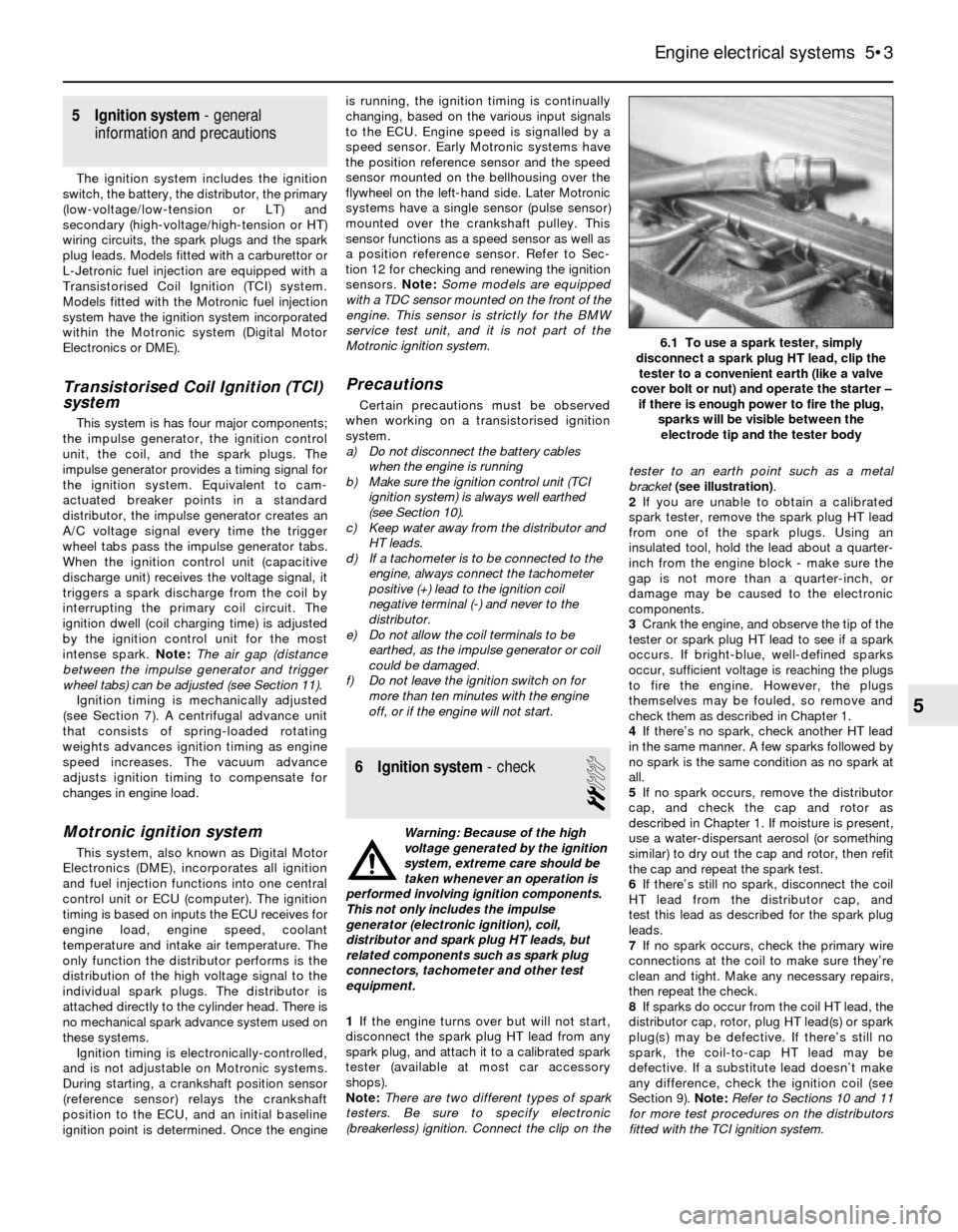
(breakerless) ignition. Connect the clip on thetester to an earth point such as a metal
bracket (see illustration).
2If you are unable to obtain a calibrated
spark tester, remove the spark plug HT lead
from one of the spark plugs. Using an
insulated tool, hold the lead about a quarter-
inch from the engine block - make sure the
gap is not more than a quarter-inch, or
damage may be caused to the electronic
components.
3Crank the engine, and observe the tip of the
tester or spark plug HT lead to see if a spark
occurs. If bright-blue, well-defined sparks
occur, sufficient voltage is reaching the plugs
to fire the engine. However, the plugs
themselves may be fouled, so remove and
check them as described in Chapter 1.
4If there’s no spark, check another HT lead
in the same manner. A few sparks followed by
no spark is the same condition as no spark at
all.
5If no spark occurs, remove the distributor
cap, and check the cap and rotor as
described in Chapter 1. If moisture is present,
use a water-dispersant aerosol (or something
similar) to dry out the cap and rotor, then refit
the cap and repeat the spark test.
6If there’s still no spark, disconnect the coil
HT lead from the distributor cap, and
test this lead as described for the spark plug
leads.
7If no spark occurs, check the primary wire
connections at the coil to make sure they’re
clean and tight. Make any necessary repairs,
then repeat the check.
8If sparks do occur from the coil HT lead, the
distributor cap, rotor, plug HT lead(s) or spark
plug(s) may be defective. If there’s still no
spark, the coil-to-cap HT lead may be
defective. If a substitute lead doesn’t make
any difference, check the ignition coil (see
Section 9). Note:Refer to Sections 10 and 11
for more test procedures on the distributors
fitted with the TCI ignition system.
Engine electrical systems 5•3
6.1 To use a spark tester, simply
disconnect a spark plug HT lead, clip the
tester to a convenient earth (like a valve
cover bolt or nut) and operate the starter –
if there is enough power to fire the plug,
sparks will be visible between the
electrode tip and the tester body
5