ECO BMW 3 SERIES 1983 E30 Repair Manual
[x] Cancel search | Manufacturer: BMW, Model Year: 1983, Model line: 3 SERIES, Model: BMW 3 SERIES 1983 E30Pages: 228, PDF Size: 7.04 MB
Page 114 of 228
7 Ignition timing (TCI system)-
check and adjustment
4
Warning: Keep hands, equipment
and wires well clear of the
viscous cooling fan during
adjustment of the ignition timing.
Note:This Section describes the procedure
for checking and adjusting the ignition timing
on engines fitted with the TCI system. On
engines fitted with the Motronic engine
management system, the ignition timing is
controlled by the electronic control unit, and
no adjustment is possible. The timing can be
checked using the following procedure, but no
ignition timing values were available at the
time of writing. If the timing is thought to be
incorrect, refer to a BMW dealer.
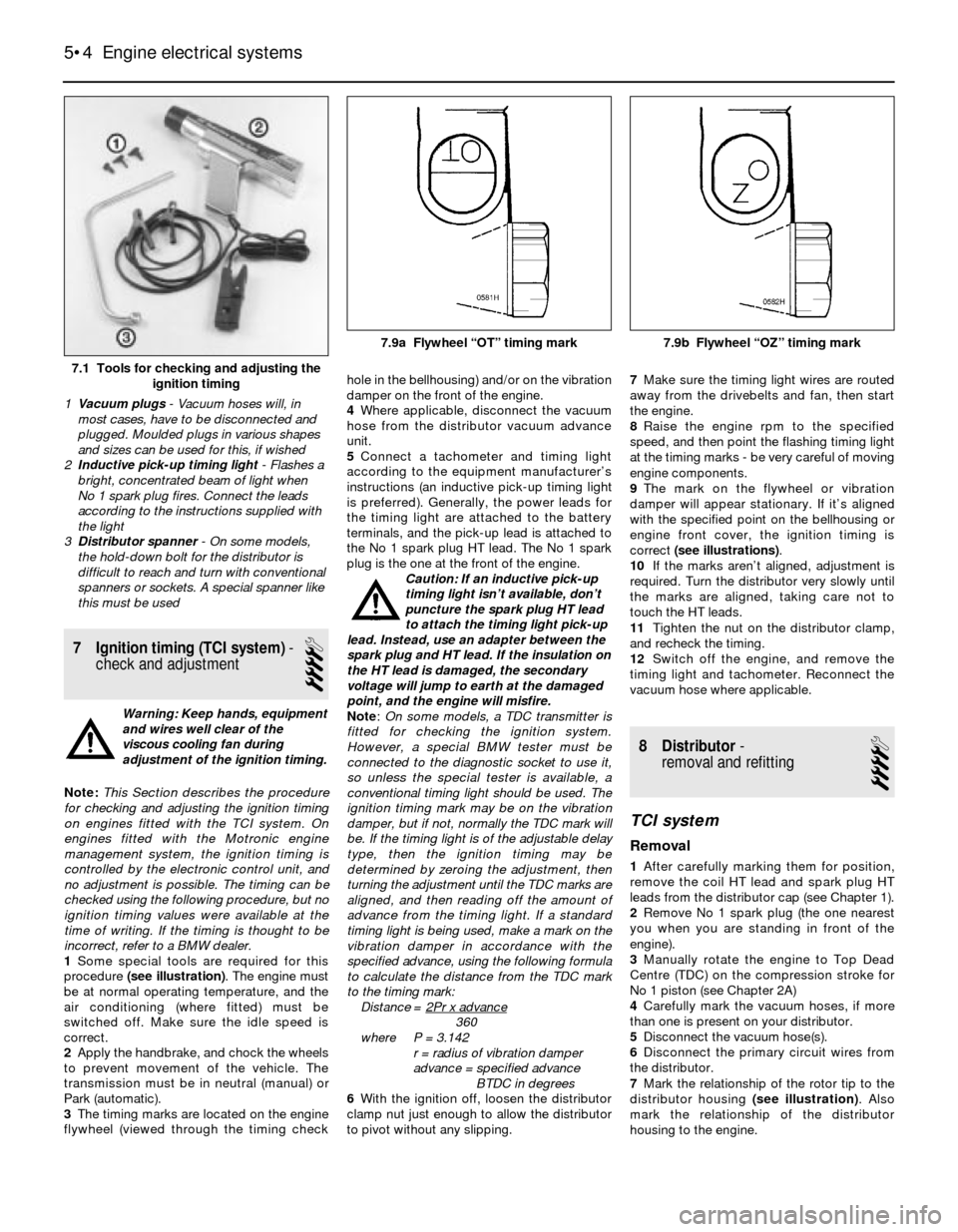
1Some special tools are required for this
procedure (see illustration). The engine must
be at normal operating temperature, and the
air conditioning (where fitted) must be
switched off. Make sure the idle speed is
correct.
2Apply the handbrake, and chock the wheels
to prevent movement of the vehicle. The
transmission must be in neutral (manual) or
Park (automatic).
3The timing marks are located on the engine
flywheel (viewed through the timing checkhole in the bellhousing) and/or on the vibration
damper on the front of the engine.
4Where applicable, disconnect the vacuum
hose from the distributor vacuum advance
unit.
5Connect a tachometer and timing light
according to the equipment manufacturer’s
instructions (an inductive pick-up timing light
is preferred). Generally, the power leads for
the timing light are attached to the battery
terminals, and the pick-up lead is attached to
the No 1 spark plug HT lead. The No 1 spark
plug is the one at the front of the engine.
Caution: If an inductive pick-up
timing light isn’t available, don’t
puncture the spark plug HT lead
to attach the timing light pick-up
lead. Instead, use an adapter between the
spark plug and HT lead. If the insulation on
the HT lead is damaged, the secondary
voltage will jump to earth at the damaged
point, and the engine will misfire.
Note:On some models, a TDC transmitter is
fitted for checking the ignition system.
However, a special BMW tester must be
connected to the diagnostic socket to use it,
so unless the special tester is available, a
conventional timing light should be used. The
ignition timing mark may be on the vibration
damper, but if not, normally the TDC mark will
be. If the timing light is of the adjustable delay
type, then the ignition timing may be
determined by zeroing the adjustment, then
turning the adjustment until the TDC marks are
aligned, and then reading off the amount of
advance from the timing light. If a standard
timing light is being used, make a mark on the
vibration damper in accordance with the
specified advance, using the following formula
to calculate the distance from the TDC mark
to the timing mark:
Distance = 2Pr x advance
360
where P = 3.142
r = radius of vibration damper
advance = specified advance
BTDC in degrees
6With the ignition off, loosen the distributor
clamp nut just enough to allow the distributor
to pivot without any slipping.7Make sure the timing light wires are routed
away from the drivebelts and fan, then start
the engine.
8Raise the engine rpm to the specified
speed, and then point the flashing timing light
at the timing marks - be very careful of moving
engine components.
9The mark on the flywheel or vibration
damper will appear stationary. If it’s aligned
with the specified point on the bellhousing or
engine front cover, the ignition timing is
correct (see illustrations).
10If the marks aren’t aligned, adjustment is
required. Turn the distributor very slowly until
the marks are aligned, taking care not to
touch the HT leads.
11Tighten the nut on the distributor clamp,
and recheck the timing.
12Switch off the engine, and remove the
timing light and tachometer. Reconnect the
vacuum hose where applicable.
8 Distributor-
removal and refitting
4
TCI system
Removal
1After carefully marking them for position,
remove the coil HT lead and spark plug HT
leads from the distributor cap (see Chapter 1).
2Remove No 1 spark plug (the one nearest
you when you are standing in front of the
engine).
3Manually rotate the engine to Top Dead
Centre (TDC) on the compression stroke for
No 1 piston (see Chapter 2A)
4Carefully mark the vacuum hoses, if more
than one is present on your distributor.
5Disconnect the vacuum hose(s).
6Disconnect the primary circuit wires from
the distributor.
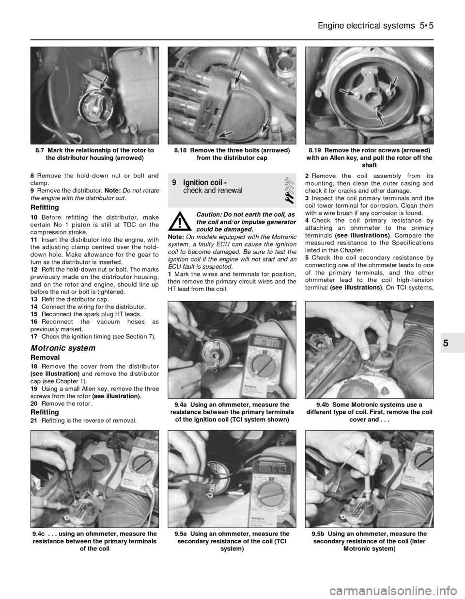
7Mark the relationship of the rotor tip to the
distributor housing (see illustration). Also
mark the relationship of the distributor
housing to the engine.
5•4 Engine electrical systems
7.1 Tools for checking and adjusting the
ignition timing
1Vacuum plugs- Vacuum hoses will, in
most cases, have to be disconnected and
plugged. Moulded plugs in various shapes
and sizes can be used for this, if wished
2Inductive pick-up timing light- Flashes a
bright, concentrated beam of light when
No 1 spark plug fires. Connect the leads
according to the instructions supplied with
the light
3Distributor spanner - On some models,
the hold-down bolt for the distributor is
difficult to reach and turn with conventional
spanners or sockets. A special spanner like
this must be used
7.9a Flywheel “OT” timing mark 7.9b Flywheel “OZ” timing mark
Page 115 of 228
8Remove the hold-down nut or bolt and
clamp.
9Remove the distributor. Note:Do not rotate
the engine with the distributor out.
Refitting
10Before refitting the distributor, make
certain No 1 piston is still at TDC on the
compression stroke.
11Insert the distributor into the engine, with
the adjusting clamp centred over the hold-
down hole. Make allowance for the gear to
turn as the distributor is inserted.
12Refit the hold-down nut or bolt. The marks
previously made on the distributor housing,
and on the rotor and engine, should line up
before the nut or bolt is tightened.
13Refit the distributor cap.
14Connect the wiring for the distributor.
15Reconnect the spark plug HT leads.
16Reconnect the vacuum hoses as
previously marked.
17Check the ignition timing (see Section 7).
Motronic system
Removal
18Remove the cover from the distributor
(see illustration)and remove the distributor
cap (see Chapter 1).
19Using a small Allen key, remove the three
screws from the rotor (see illustration).
20Remove the rotor.
Refitting
21Refitting is the reverse of removal.
9 Ignition coil -
check and renewal
2
Caution: Do not earth the coil, as
the coil and/or impulse generator
could be damaged.
Note:On models equipped with the Motronic
system, a faulty ECU can cause the ignition
coil to become damaged. Be sure to test the
ignition coil if the engine will not start and an
ECU fault is suspected.
1Mark the wires and terminals for position,
then remove the primary circuit wires and the
HT lead from the coil.2Remove the coil assembly from its
mounting, then clean the outer casing and
check it for cracks and other damage.
3Inspect the coil primary terminals and the
coil tower terminal for corrosion. Clean them
with a wire brush if any corrosion is found.
4Check the coil primary resistance by
attaching an ohmmeter to the primary
terminals (see illustrations). Compare the
measured resistance to the Specifications
listed in this Chapter.
5Check the coil secondary resistance by
connecting one of the ohmmeter leads to one
of the primary terminals, and the other
ohmmeter lead to the coil high-tension
terminal (see illustrations). On TCI systems,
Engine electrical systems 5•5
8.19 Remove the rotor screws (arrowed)
with an Allen key, and pull the rotor off the
shaft8.18 Remove the three bolts (arrowed)
from the distributor cap8.7 Mark the relationship of the rotor to
the distributor housing (arrowed)
9.5b Using an ohmmeter, measure the
secondary resistance of the coil (later
Motronic system)9.5a Using an ohmmeter, measure the
secondary resistance of the coil (TCI
system)
9.4b Some Motronic systems use a
different type of coil. First, remove the coil
cover and . . .9.4a Using an ohmmeter, measure the
resistance between the primary terminals
of the ignition coil (TCI system shown)
9.4c . . . using an ohmmeter, measure the
resistance between the primary terminals
of the coil
5
Page 116 of 228
connect the ohmmeter to coil terminal 1 (-)
and the centre tower. On Motronic systems,
connect the ohmmeter to coil terminal 15 (+)
and the centre tower. Compare the measured
resistance with the values given in the Specifi-
cations in this Chapter.
6If the measured resistances are not close to
those specified, the coil is defective and
should be renewed. Note that the measured
resistance will vary according to the
temperature of the coil, so don’t rush to
condemn the coil if the resistance is only a
little way out.
7It is essential for proper ignition system
operation that all coil terminals and wire leads
be kept clean and dry.
8Refit the coil in its mounting, and reconnect
the wiring. Refitting is the reverse of removal.
10 Impulse generator and
ignition control unit- check
and renewal (TCI system)
3
1The impulse generator (located in the
distributor) and ignition control unit need to be
tested in the event there is no spark at the
spark plugs. Make sure the plug leads,
ignition coil and spark plugs are working
properly (see Sections 6 and 9). There are two
types of control units; Bosch or
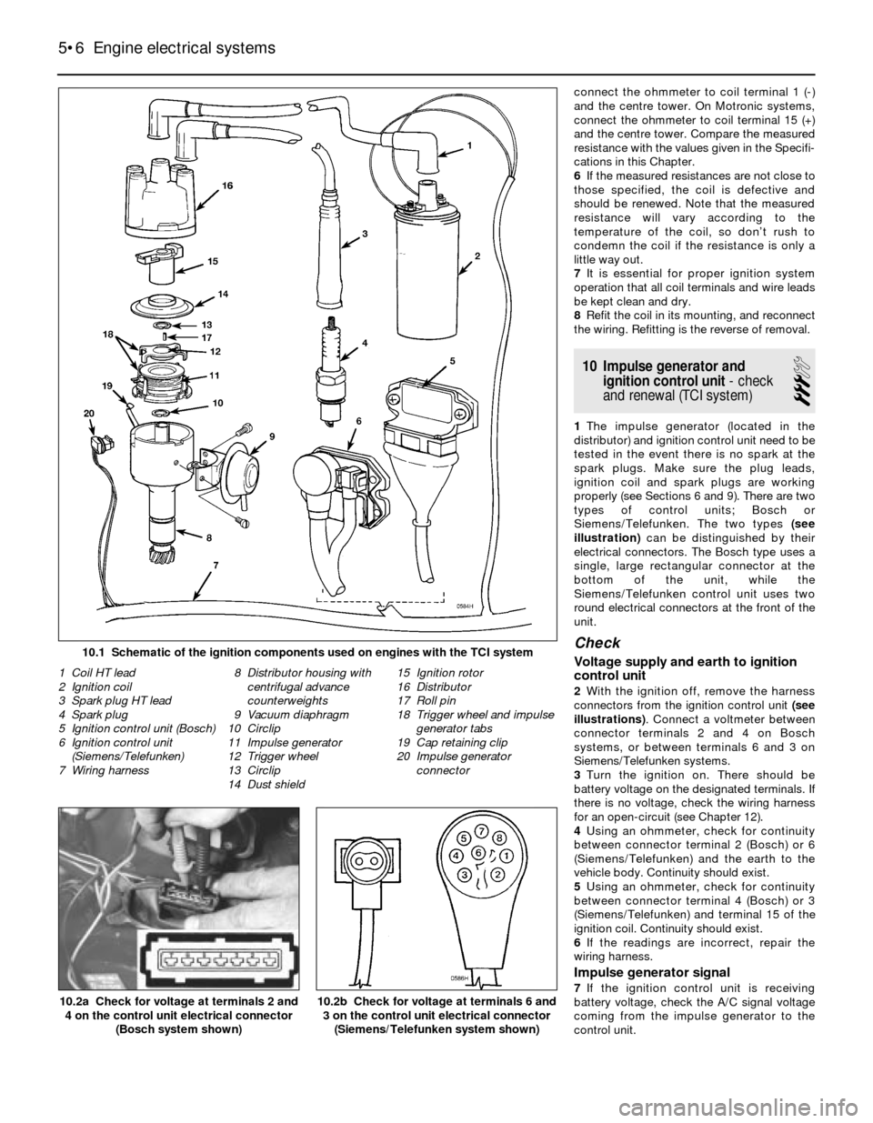
Siemens/Telefunken. The two types (see
illustration)can be distinguished by their
electrical connectors. The Bosch type uses a
single, large rectangular connector at the
bottom of the unit, while the
Siemens/Telefunken control unit uses two
round electrical connectors at the front of the
unit.
Check
Voltage supply and earth to ignition
control unit
2With the ignition off, remove the harness
connectors from the ignition control unit (see
illustrations). Connect a voltmeter between
connector terminals 2 and 4 on Bosch
systems, or between terminals 6 and 3 on
Siemens/Telefunken systems.
3Turn the ignition on. There should be
battery voltage on the designated terminals. If
there is no voltage, check the wiring harness
for an open-circuit (see Chapter 12).
4Using an ohmmeter, check for continuity
between connector terminal 2 (Bosch) or 6
(Siemens/Telefunken) and the earth to the
vehicle body. Continuity should exist.
5Using an ohmmeter, check for continuity
between connector terminal 4 (Bosch) or 3
(Siemens/Telefunken) and terminal 15 of the
ignition coil. Continuity should exist.
6If the readings are incorrect, repair the
wiring harness.
Impulse generator signal
7If the ignition control unit is receiving
battery voltage, check the A/C signal voltage
coming from the impulse generator to the
control unit.
5•6 Engine electrical systems
10.2b Check for voltage at terminals 6 and
3 on the control unit electrical connector
(Siemens/Telefunken system shown)10.2a Check for voltage at terminals 2 and
4 on the control unit electrical connector
(Bosch system shown)
1 Coil HT lead
2 Ignition coil
3 Spark plug HT lead
4 Spark plug
5 Ignition control unit (Bosch)
6 Ignition control unit
(Siemens/Telefunken)
7 Wiring harness8 Distributor housing with
centrifugal advance
counterweights
9 Vacuum diaphragm
10 Circlip
11 Impulse generator
12 Trigger wheel
13 Circlip
14 Dust shield15 Ignition rotor
16 Distributor
17 Roll pin
18 Trigger wheel and impulse
generator tabs
19 Cap retaining clip
20 Impulse generator
connector
10.1 Schematic of the ignition components used on engines with the TCI system
Page 119 of 228
Withdraw the sensor from its bracket and
remove it.
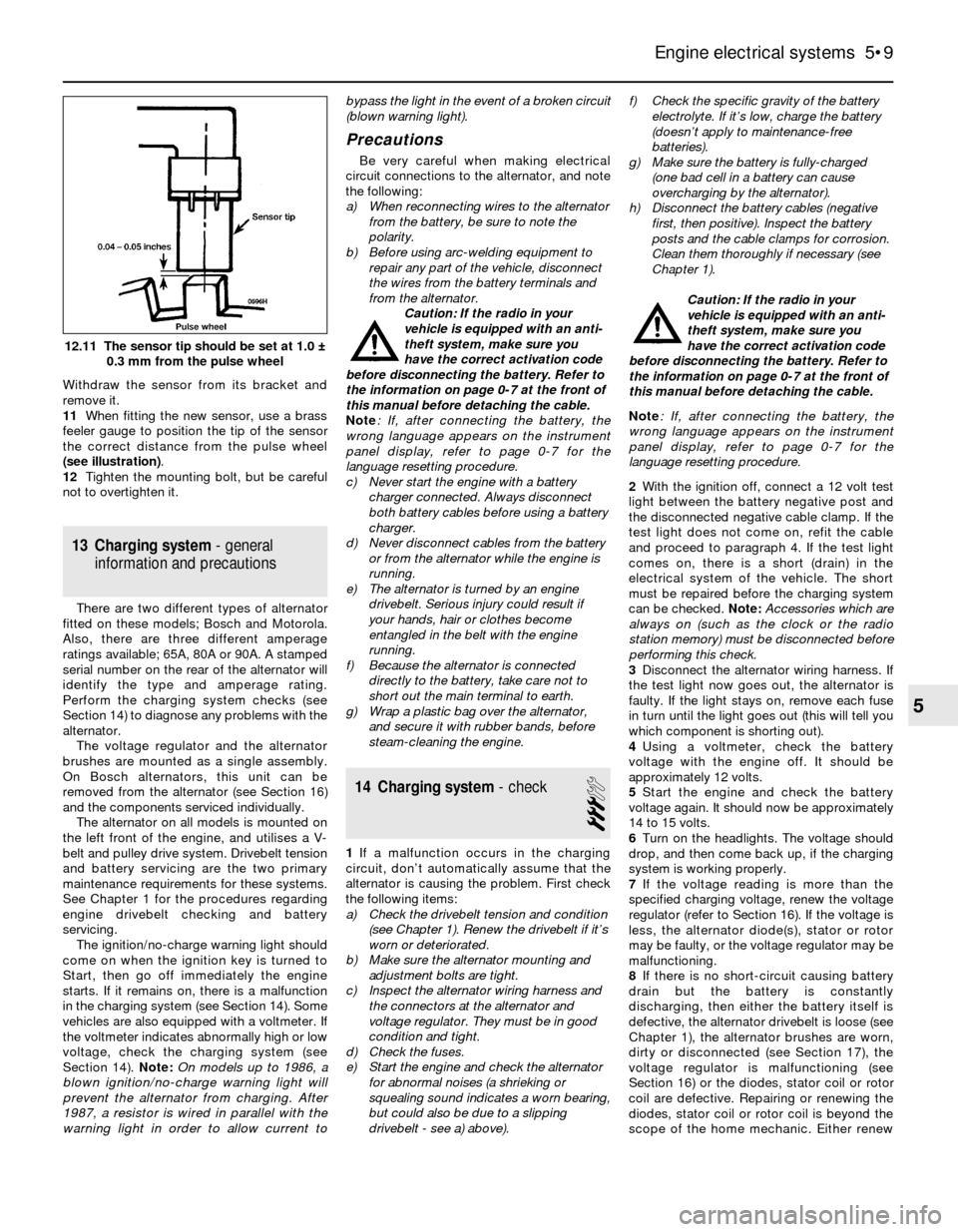
11When fitting the new sensor, use a brass
feeler gauge to position the tip of the sensor
the correct distance from the pulse wheel
(see illustration).
12Tighten the mounting bolt, but be careful
not to overtighten it.
13 Charging system- general
information and precautions
There are two different types of alternator
fitted on these models; Bosch and Motorola.
Also, there are three different amperage
ratings available; 65A, 80A or 90A. A stamped
serial number on the rear of the alternator will
identify the type and amperage rating.
Perform the charging system checks (see
Section 14) to diagnose any problems with the
alternator.
The voltage regulator and the alternator
brushes are mounted as a single assembly.
On Bosch alternators, this unit can be
removed from the alternator (see Section 16)
and the components serviced individually.
The alternator on all models is mounted on
the left front of the engine, and utilises a V-
belt and pulley drive system. Drivebelt tension
and battery servicing are the two primary
maintenance requirements for these systems.
See Chapter 1 for the procedures regarding
engine drivebelt checking and battery
servicing.
The ignition/no-charge warning light should
come on when the ignition key is turned to
Start, then go off immediately the engine
starts. If it remains on, there is a malfunction
in the charging system (see Section 14). Some
vehicles are also equipped with a voltmeter. If
the voltmeter indicates abnormally high or low
voltage, check the charging system (see
Section 14). Note:On models up to 1986, a
blown ignition/no-charge warning light will
prevent the alternator from charging. After
1987, a resistor is wired in parallel with the
warning light in order to allow current tobypass the light in the event of a broken circuit
(blown warning light).
Precautions
Be very careful when making electrical
circuit connections to the alternator, and note
the following:
a) When reconnecting wires to the alternator
from the battery, be sure to note the
polarity.
b) Before using arc-welding equipment to
repair any part of the vehicle, disconnect
the wires from the battery terminals and
from the alternator.
Caution: If the radio in your
vehicle is equipped with an anti-
theft system, make sure you
have the correct activation code
before disconnecting the battery. Refer to
the information on page 0-7 at the front of
this manual before detaching the cable.
Note: If, after connecting the battery, the
wrong language appears on the instrument
panel display, refer to page 0-7 for the
language resetting procedure.
c) Never start the engine with a battery
charger connected. Always disconnect
both battery cables before using a battery
charger.
d) Never disconnect cables from the battery
or from the alternator while the engine is
running.
e) The alternator is turned by an engine
drivebelt. Serious injury could result if
your hands, hair or clothes become
entangled in the belt with the engine
running.
f) Because the alternator is connected
directly to the battery, take care not to
short out the main terminal to earth.
g) Wrap a plastic bag over the alternator,
and secure it with rubber bands, before
steam-cleaning the engine.
14 Charging system- check
3
1If a malfunction occurs in the charging
circuit, don’t automatically assume that the
alternator is causing the problem. First check
the following items:
a) Check the drivebelt tension and condition
(see Chapter 1). Renew the drivebelt if it’s
worn or deteriorated.
b) Make sure the alternator mounting and
adjustment bolts are tight.
c) Inspect the alternator wiring harness and
the connectors at the alternator and
voltage regulator. They must be in good
condition and tight.
d) Check the fuses.
e) Start the engine and check the alternator
for abnormal noises (a shrieking or
squealing sound indicates a worn bearing,
but could also be due to a slipping
drivebelt - see a) above).f) Check the specific gravity of the battery
electrolyte. If it’s low, charge the battery
(doesn’t apply to maintenance-free
batteries).
g) Make sure the battery is fully-charged
(one bad cell in a battery can cause
overcharging by the alternator).
h) Disconnect the battery cables (negative
first, then positive). Inspect the battery
posts and the cable clamps for corrosion.
Clean them thoroughly if necessary (see
Chapter 1).
Caution: If the radio in your
vehicle is equipped with an anti-
theft system, make sure you
have the correct activation code
before disconnecting the battery. Refer to
the information on page 0-7 at the front of
this manual before detaching the cable.
Note: If, after connecting the battery, the
wrong language appears on the instrument
panel display, refer to page 0-7 for the
language resetting procedure.
2With the ignition off, connect a 12 volt test
light between the battery negative post and
the disconnected negative cable clamp. If the
test light does not come on, refit the cable
and proceed to paragraph 4. If the test light
comes on, there is a short (drain) in the
electrical system of the vehicle. The short
must be repaired before the charging system
can be checked. Note: Accessories which are
always on (such as the clock or the radio
station memory) must be disconnected before
performing this check.
3Disconnect the alternator wiring harness. If
the test light now goes out, the alternator is
faulty. If the light stays on, remove each fuse
in turn until the light goes out (this will tell you
which component is shorting out).
4Using a voltmeter, check the battery
voltage with the engine off. It should be
approximately 12 volts.
5Start the engine and check the battery
voltage again. It should now be approximately
14 to 15 volts.
6Turn on the headlights. The voltage should
drop, and then come back up, if the charging
system is working properly.
7If the voltage reading is more than the
specified charging voltage, renew the voltage
regulator (refer to Section 16). If the voltage is
less, the alternator diode(s), stator or rotor
may be faulty, or the voltage regulator may be
malfunctioning.
8If there is no short-circuit causing battery
drain but the battery is constantly
discharging, then either the battery itself is
defective, the alternator drivebelt is loose (see
Chapter 1), the alternator brushes are worn,
dirty or disconnected (see Section 17), the
voltage regulator is malfunctioning (see
Section 16) or the diodes, stator coil or rotor
coil are defective. Repairing or renewing the
diodes, stator coil or rotor coil is beyond the
scope of the home mechanic. Either renew
Engine electrical systems 5•9
12.11 The sensor tip should be set at 1.0 ±
0.3 mm from the pulse wheel
5
Page 120 of 228
the alternator complete, or take it to an
automotive electrician, who may be able to
overhaul it. Note:On models up to 1986, a
blown ignition/no-charge warning light bulb
will prevent the alternator from charging. After
1987, a resistor is wired in parallel with the
warning light, in order to allow current to
bypass the light in the event of a broken circuit
(blown warning light).
15 Alternator-
removal and refitting
1
Caution: If the radio in your
vehicle is equipped with an anti-
theft system, make sure you
have the correct activation code
before disconnecting the battery. Refer to
the information on page 0-7 at the front of
this manual before detaching the cable.
Note: If, after connecting the battery, the
wrong language appears on the instrument
panel display, refer to page 0-7 for the
language resetting procedure.
Removal
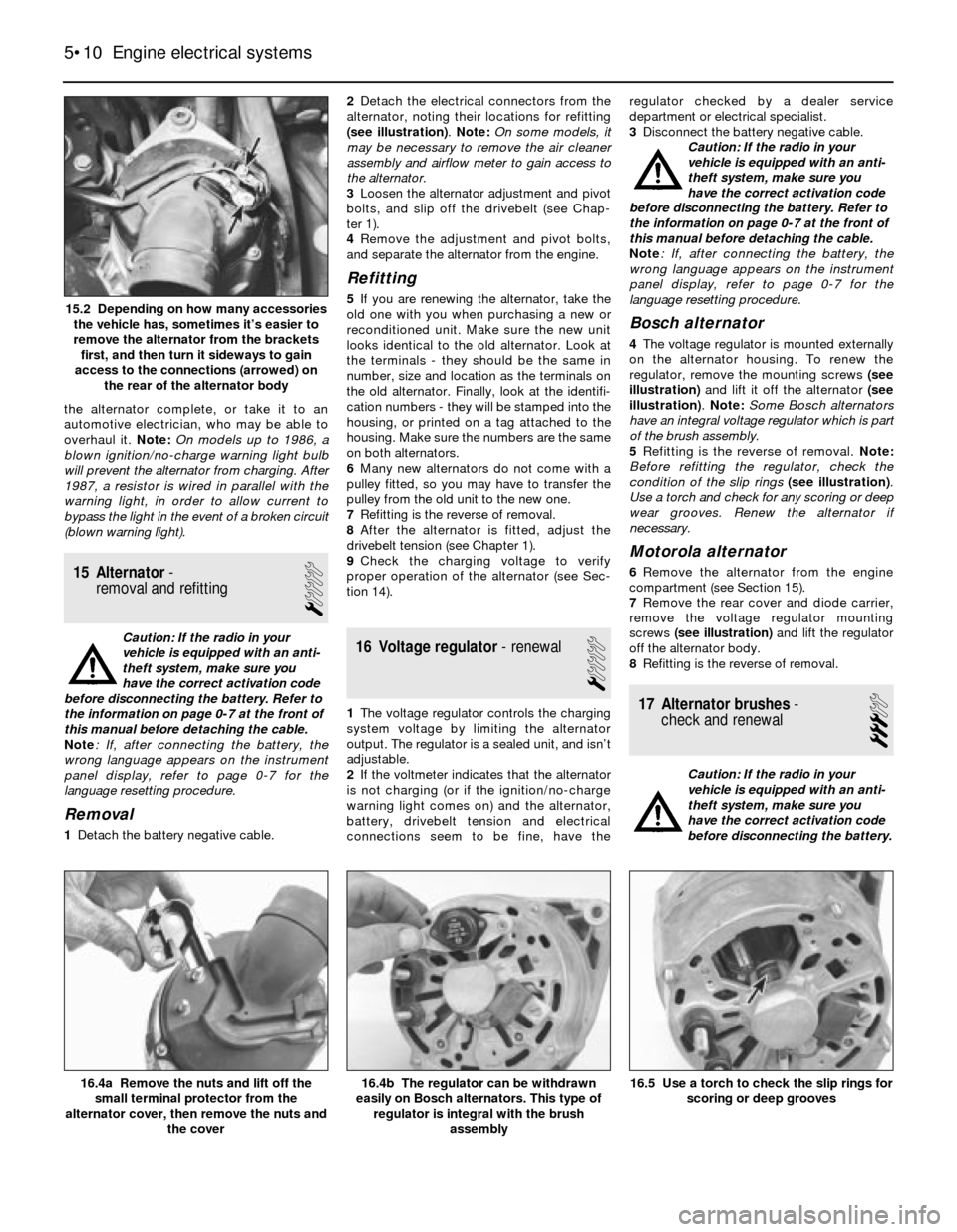
1Detach the battery negative cable.2Detach the electrical connectors from the
alternator, noting their locations for refitting
(see illustration). Note: On some models, it
may be necessary to remove the air cleaner
assembly and airflow meter to gain access to
the alternator.
3Loosen the alternator adjustment and pivot
bolts, and slip off the drivebelt (see Chap-
ter 1).
4Remove the adjustment and pivot bolts,
and separate the alternator from the engine.
Refitting
5If you are renewing the alternator, take the
old one with you when purchasing a new or
reconditioned unit. Make sure the new unit
looks identical to the old alternator. Look at
the terminals - they should be the same in
number, size and location as the terminals on
the old alternator. Finally, look at the identifi-
cation numbers - they will be stamped into the
housing, or printed on a tag attached to the
housing. Make sure the numbers are the same
on both alternators.
6Many new alternators do not come with a
pulley fitted, so you may have to transfer the
pulley from the old unit to the new one.
7Refitting is the reverse of removal.
8After the alternator is fitted, adjust the
drivebelt tension (see Chapter 1).
9Check the charging voltage to verify
proper operation of the alternator (see Sec-
tion 14).
16 Voltage regulator- renewal
1
1The voltage regulator controls the charging
system voltage by limiting the alternator
output. The regulator is a sealed unit, and isn’t
adjustable.
2If the voltmeter indicates that the alternator
is not charging (or if the ignition/no-charge
warning light comes on) and the alternator,
battery, drivebelt tension and electrical
connections seem to be fine, have theregulator checked by a dealer service
department or electrical specialist.
3Disconnect the battery negative cable.
Caution: If the radio in your
vehicle is equipped with an anti-
theft system, make sure you
have the correct activation code
before disconnecting the battery. Refer to
the information on page 0-7 at the front of
this manual before detaching the cable.
Note: If, after connecting the battery, the
wrong language appears on the instrument
panel display, refer to page 0-7 for the
language resetting procedure.
Bosch alternator
4The voltage regulator is mounted externally
on the alternator housing. To renew the
regulator, remove the mounting screws (see
illustration)and lift it off the alternator (see
illustration). Note: Some Bosch alternators
have an integral voltage regulator which is part
of the brush assembly.
5Refitting is the reverse of removal. Note:
Before refitting the regulator, check the
condition of the slip rings(see illustration).
Use a torch and check for any scoring or deep
wear grooves. Renew the alternator if
necessary.
Motorola alternator
6Remove the alternator from the engine
compartment (see Section 15).
7Remove the rear cover and diode carrier,
remove the voltage regulator mounting
screws (see illustration)and lift the regulator
off the alternator body.
8Refitting is the reverse of removal.
17 Alternator brushes-
check and renewal
3
Caution: If the radio in your
vehicle is equipped with an anti-
theft system, make sure you
have the correct activation code
before disconnecting the battery.
5•10 Engine electrical systems
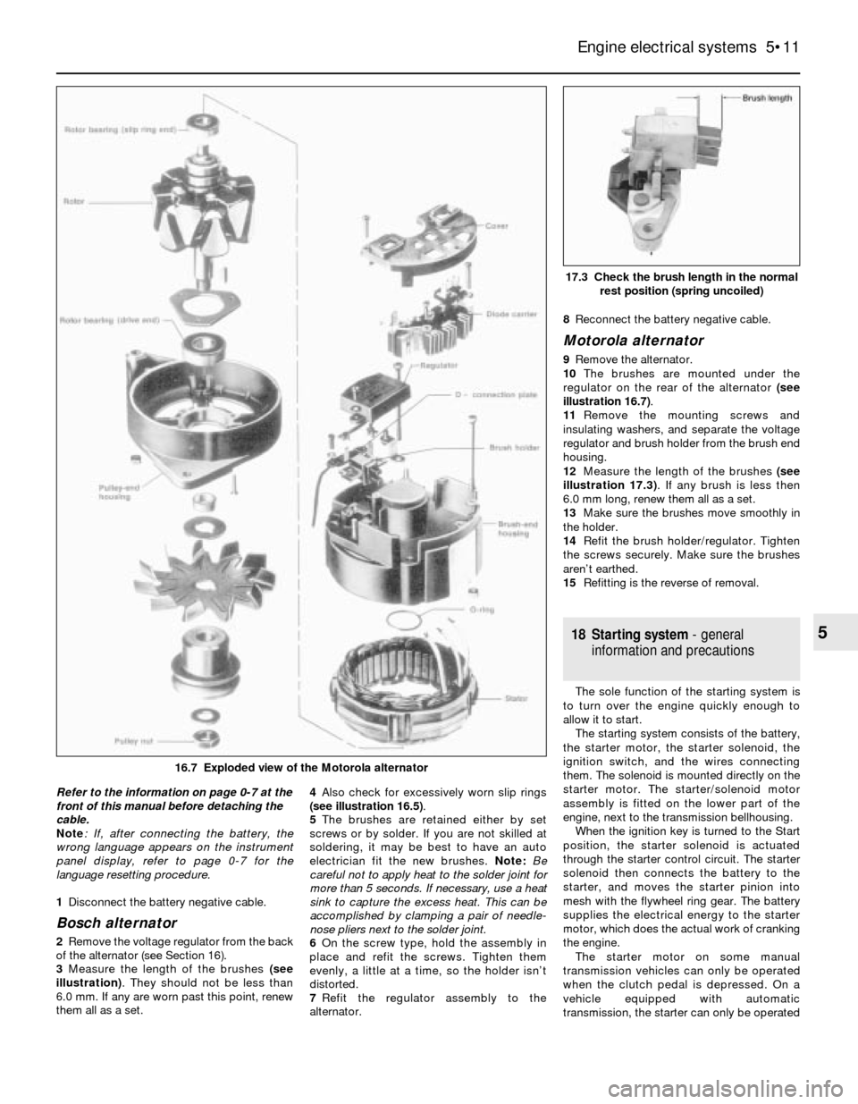
16.5 Use a torch to check the slip rings for
scoring or deep grooves16.4b The regulator can be withdrawn
easily on Bosch alternators. This type of
regulator is integral with the brush
assembly16.4a Remove the nuts and lift off the
small terminal protector from the
alternator cover, then remove the nuts and
the cover
15.2 Depending on how many accessories
the vehicle has, sometimes it’s easier to
remove the alternator from the brackets
first, and then turn it sideways to gain
access to the connections (arrowed) on
the rear of the alternator body
Page 121 of 228
Refer to the information on page 0-7 at the
front of this manual before detaching the
cable.
Note: If, after connecting the battery, the
wrong language appears on the instrument
panel display, refer to page 0-7 for the
language resetting procedure.
1Disconnect the battery negative cable.
Bosch alternator
2Remove the voltage regulator from the back
of the alternator (see Section 16).
3Measure the length of the brushes (see
illustration). They should not be less than
6.0 mm. If any are worn past this point, renew
them all as a set. 4Also check for excessively worn slip rings
(see illustration 16.5).
5The brushes are retained either by set
screws or by solder. If you are not skilled at
soldering, it may be best to have an auto
electrician fit the new brushes. Note: Be
careful not to apply heat to the solder joint for
more than 5 seconds. If necessary, use a heat
sink to capture the excess heat. This can be
accomplished by clamping a pair of needle-
nose pliers next to the solder joint.
6On the screw type, hold the assembly in
place and refit the screws. Tighten them
evenly, a little at a time, so the holder isn’t
distorted.
7Refit the regulator assembly to the
alternator.8Reconnect the battery negative cable.
Motorola alternator
9Remove the alternator.
10The brushes are mounted under the
regulator on the rear of the alternator (see
illustration 16.7).
11Remove the mounting screws and
insulating washers, and separate the voltage
regulator and brush holder from the brush end
housing.
12Measure the length of the brushes (see
illustration 17.3). If any brush is less then
6.0 mm long, renew them all as a set.
13Make sure the brushes move smoothly in
the holder.
14Refit the brush holder/regulator. Tighten
the screws securely. Make sure the brushes
aren’t earthed.
15Refitting is the reverse of removal.
18 Starting system- general
information and precautions
The sole function of the starting system is
to turn over the engine quickly enough to
allow it to start.
The starting system consists of the battery,
the starter motor, the starter solenoid, the
ignition switch, and the wires connecting
them. The solenoid is mounted directly on the
starter motor. The starter/solenoid motor
assembly is fitted on the lower part of the
engine, next to the transmission bellhousing.
When the ignition key is turned to the Start
position, the starter solenoid is actuated
through the starter control circuit. The starter
solenoid then connects the battery to the
starter, and moves the starter pinion into
mesh with the flywheel ring gear. The battery
supplies the electrical energy to the starter
motor, which does the actual work of cranking
the engine.
The starter motor on some manual
transmission vehicles can only be operated
when the clutch pedal is depressed. On a
vehicle equipped with automatic
transmission, the starter can only be operated
Engine electrical systems 5•11
17.3 Check the brush length in the normal
rest position (spring uncoiled)
5
16.7 Exploded view of the Motorola alternator
Page 122 of 228
when the transmission selector lever is in Park
or Neutral.
Always detach the battery negative cable
before working on the starting system.
19 Starter motor-
in-vehicle check
2
Note:Before diagnosing starter problems,
make sure the battery is fully charged.
1If the starter motor does not turn at all when
the switch is operated, make sure that the
gear lever is in Neutral or Park (automatic
transmission) or, where applicable, that the
clutch pedal is depressed (manual
transmission).
2Make sure that the battery is charged, and
that all cables, both at the battery and starter
solenoid terminals, are clean and secure.
3If the starter motor spins but the engine is
not cranking, the overrun clutch in the starter
motor is slipping, and the starter motor must
be renewed.
4If, when the switch is actuated, the starter
motor does not operate at all but the solenoid
clicks, then the problem lies either in the
battery, the main solenoid contacts, or the
starter motor itself (or the engine is seized).
5If the solenoid plunger cannot be heard
when the switch is actuated, the battery is
faulty, the switch is defective, the fusible link
is burned-out (the circuit is open), or the
solenoid itself is defective.
6To check the solenoid, connect a jumper
lead between the battery (+) and the ignition
switch wire terminal (the small terminal) on the
solenoid. If the starter motor now operates,
the solenoid is OK and the problem is in the
ignition switch, starter inhibitor switch
(automatic transmission models), clutch
switch (some manual transmission models), or
the wiring.
7If the starter motor still does not operate,
remove the starter/solenoid assembly for
dismantling, testing and repair.
8If the starter motor cranks the engine at an
abnormally-slow speed, first make sure that
the battery is charged, and that all terminal
connections are tight. If the engine is partially-
seized, or has the wrong viscosity oil in it, it
will crank slowly.
9Run the engine until normal operating
temperature is reached, then disconnect the
coil HT lead from the distributor cap and earth
it on the engine.
10Connect a voltmeter positive lead to the
battery positive post, and connect the
negative lead to the negative post.11Crank the engine, and take the voltmeter
readings as soon as a steady figure is
indicated. Do not allow the starter motor to
turn for more than 10 seconds at a time. A
reading of 9 volts or more, with the starter
motor turning at normal cranking speed, is
normal. If the reading is 9 volts or more but
the cranking speed is slow, the solenoid
contacts are burned, there is a bad
connection, or the starter motor itself is faulty.
If the reading is less than 9 volts and the
cranking speed is slow, the starter motor is
faulty or the battery is responsible (defective
or discharged).
20 Starter motor-
removal and refitting
1
Note:If the starter motor is defective, it should
be renewed, or taken to an auto electrical
specialist for repair. Overhaul of the starter
motor is unlikely to be a practical proposition
for the home mechanic, even if spare parts are
available. However, the solenoid can be
renewed separately (see Section 21).
Removal
Caution: If the radio in your
vehicle is equipped with an anti-
theft system, make sure you
have the correct activation code
before disconnecting the battery. Refer to
the information on page 0-7 at the front of
this manual before detaching the cable.
Note: If, after connecting the battery, the
wrong language appears on the instrument
panel display, refer to page 0-7 for the
language resetting procedure.
1Detach the battery negative cable.
2Raise the vehicle and support it securely on
axle stands.
3Clearly label the wires from the terminals onthe starter motor and solenoid, then
disconnect them. Note: On some models, it
may be necessary to remove the air cleaner
(see Chapter 4), coolant expansion tank (see
Chapter 3) and the heater hoses to gain
access to the top of the starter. Carefully label
any hoses or components that need to be
removed from the engine compartment, to
avoid confusion when reassembling.
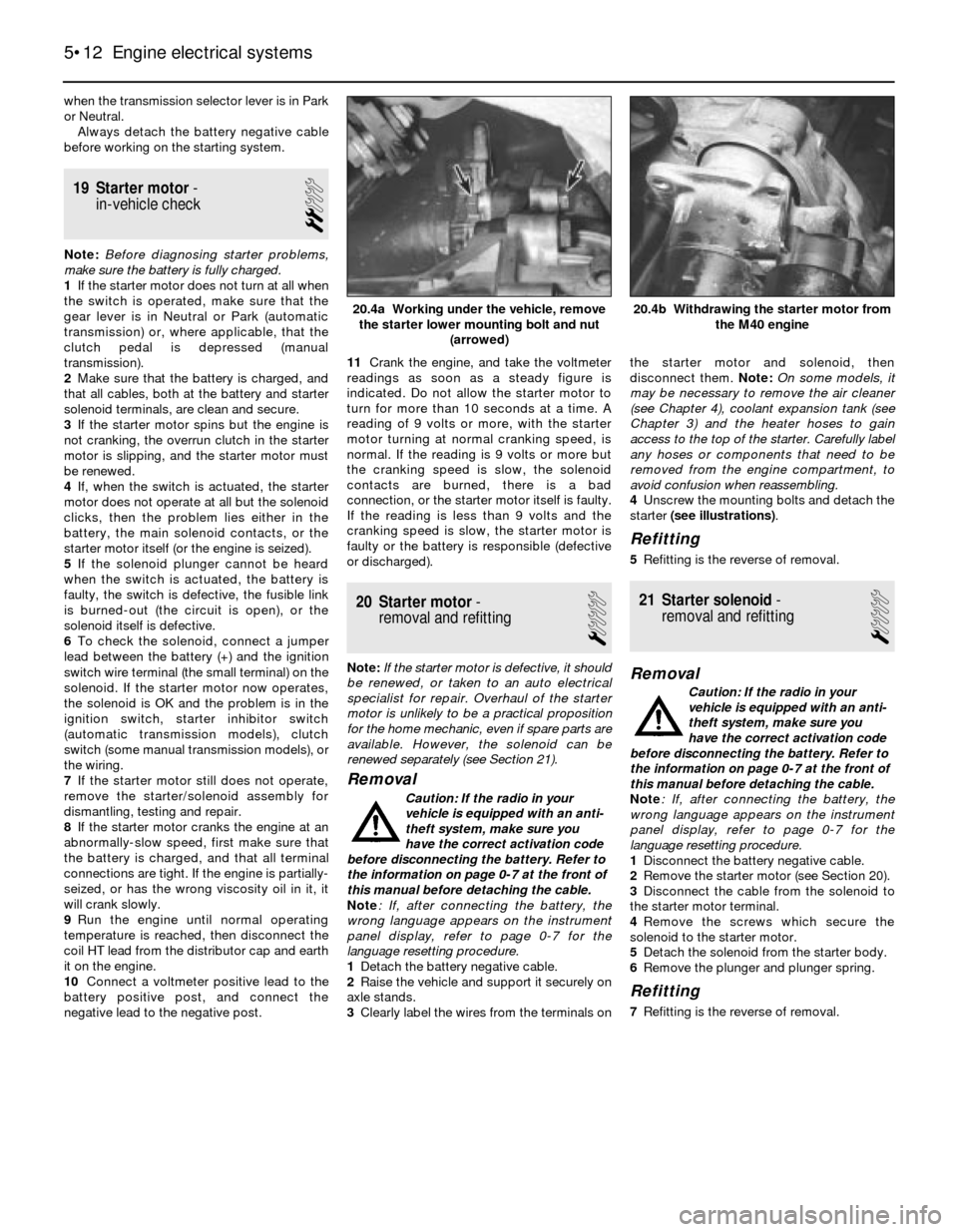
4Unscrew the mounting bolts and detach the
starter (see illustrations).
Refitting
5Refitting is the reverse of removal.
21 Starter solenoid-
removal and refitting
1
Removal
Caution: If the radio in your
vehicle is equipped with an anti-
theft system, make sure you
have the correct activation code
before disconnecting the battery. Refer to
the information on page 0-7 at the front of
this manual before detaching the cable.
Note: If, after connecting the battery, the
wrong language appears on the instrument
panel display, refer to page 0-7 for the
language resetting procedure.
1Disconnect the battery negative cable.
2Remove the starter motor (see Section 20).
3Disconnect the cable from the solenoid to
the starter motor terminal.
4Remove the screws which secure the
solenoid to the starter motor.
5Detach the solenoid from the starter body.
6Remove the plunger and plunger spring.
Refitting
7Refitting is the reverse of removal.
5•12 Engine electrical systems
20.4b Withdrawing the starter motor from
the M40 engine20.4a Working under the vehicle, remove
the starter lower mounting bolt and nut
(arrowed)
Page 123 of 228
6
Chapter 6
Engine management and emission control systems
Catalytic converter . . . . . . . . . . . . . . . . . . . . . . . . . . . . . . . . . . . . . . 7
Electronic Control Unit (ECU) - removal and refitting . . . . . . . . . . . . 3
Evaporative emissions control (EVAP) system . . . . . . . . . . . . . . . . . 6
Evaporative emissions control system inspection . . . See Chapter 1
General information . . . . . . . . . . . . . . . . . . . . . . . . . . . . . . . . . . . . . . 1Information sensors . . . . . . . . . . . . . . . . . . . . . . . . . . . . . . . . . . . . . . 4
Motronic engine management system self-diagnosis -
general information . . . . . . . . . . . . . . . . . . . . . . . . . . . . . . . . . . . . 2
Positive crankcase ventilation (PCV) system . . . . . . . . . . . . . . . . . . 5
6•1
Easy,suitable for
novice with little
experienceFairly easy,suitable
for beginner with
some experienceFairly difficult,
suitable for competent
DIY mechanic
Difficult,suitable for
experienced DIY
mechanicVery difficult,
suitable for expert
DIY or professional
Degrees of difficulty Contents
1 General information
To prevent pollution of the atmosphere
from incomplete combustion or evaporation
of the fuel, and to maintain good driveability
and fuel economy, a number of emission
control systems are used on these vehicles.
Not all of these systems are fitted to all
models, but they include the following:
Catalytic converter
Evaporative emission control (EVAP) system
Positive crankcase ventilation (PCV) system
Electronic engine management
The Sections in this Chapter include
general descriptions and checking
procedures within the scope of the home
mechanic, as well as component renewal
procedures (when possible) for each of the
systems listed above.
Before assuming that an emissions control
system is malfunctioning, check the fuel and
ignition systems carefully. The diagnosis of
some emission control devices requires
specialised tools, equipment and training. If
checking and servicing become too difficult,
or if a procedure is beyond your ability,
consult a dealer service department or other
specialist.This doesn’t mean, however, that emission
control systems are particularly difficult to
maintain and repair. You can quickly and
easily perform many checks, and do most of
the regular maintenance at home with
common tune-up and hand tools.
Pay close attention to any special
precautions outlined in this Chapter. It should
be noted that the illustrations of the various
systems may not exactly match the system
fitted on your vehicle because of
changes made by the manufacturer during
production.
2 Motronic engine management
system self-diagnosis-
general information
The Motronic engine management system
control unit (computer) has a built-in self-
diagnosis system, which detects malfunctions
in the system sensors and stores them as
fault codes in its memory. It is not possible
without dedicated test equipment to extract
these fault codes from the control unit.
However, the procedures given in Chapters 4
and 5 may be used to check individual
components and sensors of the Motronic
system. If this fails to pinpoint a fault, then the
vehicle should be taken to a BMW dealer, who
will have the necessary diagnostic
equipment to call up the fault codes from the
control unit. You will then have the
option to repair the fault yourself, or
alternatively have the fault repaired by the
BMW dealer.
3 Electronic control unit (ECU)
- removal and refitting
2
Removal
1The Electronic Control Unit (ECU) is located
either inside the passenger compartment
under the right-hand side of the facia panel on
3-Series models, or in the engine
compartment on the right-hand side on 5-
Series models (see Chapter 4).
2Disconnect the battery negative cable.
Caution: If the radio in your
vehicle is equipped with an anti-
theft system, make sure you
have the correct activation code
before disconnecting the battery. Refer to
the information on page 0-7 at the front of
this manual before detaching the cable.
Note: If, after connecting the battery, the
wrong language appears on the instrument
panel display, refer to page 0-7 for the
language resetting procedure.
3First remove the access cover on models
with the ECU on the right-hand side of the
engine compartment (see Chapter 4).
4If the ECU is located inside the vehicle,
remove the access cover on the right-hand side.
5Unplug the electrical connectors from the
ECU.
6Remove the retaining bolts from the ECU
bracket.
7Carefully remove the ECU. Note: Avoid static
electricity damage to the ECU by wearing rubber
gloves, and do not touch the connector pins.
Refitting
8Refitting is a reversal of removal.
The most frequent cause of
emission system problems is
simply a leaking vacuum hose
or loose wire, so always
check the hose and wiring connections
first.
Page 125 of 228
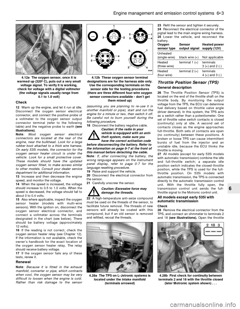
Check
12Warm up the engine, and let it run at idle.
Disconnect the oxygen sensor electrical
connector, and connect the positive probe of
a voltmeter to the oxygen sensor output
connector terminal (refer to the following
table) and the negative probe to earth (see
illustrations).
Note:Most oxygen sensor electrical
connectors are located at the rear of the
engine, near the bulkhead. Look for a large
rubber boot attached to a thick wire harness.
On early 535i models, the connector for the
oxygen sensor heater circuit is under the
vehicle. Look for a small protective cover.
These models should have the updated
oxygen sensor fitted, to make access similar
to other models. Consult your dealer service
department for additional information.
13Increase and then decrease the engine
speed, and monitor the voltage.
14When the speed is increased, the voltage
should increase to 0.5 to 1.0 volts. When the
speed is decreased, the voltage should fall to
about 0 to 0.4 volts.
15Also where applicable, inspect the oxygen
sensor heater (models with multi-wire
sensors). With the ignition on, disconnect the
oxygen sensor electrical connector, and
connect a voltmeter across the terminals
designated in the chart (see below). There
should be battery voltage (approximately
12 volts).
16If the reading is not correct, check the
oxygen sensor heater relay (see Chapter 12).
If the information is not available, check the
owner’s handbook for the exact location of
the oxygen sensor heater relay. The relay
should receive battery voltage.
17If the oxygen sensor fails any of these
tests, renew it.
Renewal
Note: Because it is fitted in the exhaust
manifold, converter or pipe, which contracts
when cool, the oxygen sensor may be very
difficult to loosen when the engine is cold.
Rather than risk damage to the sensor(assuming you are planning to re-use it in
another manifold or pipe), start and run the
engine for a minute or two, then switch it off.
Be careful not to burn yourself during the
following procedure.
18Disconnect the battery negative cable.
Caution: If the radio in your
vehicle is equipped with an anti-
theft system, make sure you
have the correct activation code
before disconnecting the battery. Refer to
the information on page 0-7 at the front of
this manual before detaching the cable.
Note: If, after connecting the battery, the
wrong language appears on the instrument
panel display, refer to page 0-7 for the
language resetting procedure.
19Raise and support the vehicle.
20Disconnect the electrical connector from
the sensor.
21Carefully unscrew the sensor.
Caution: Excessive force may
damage the threads.
22A high-temperature anti-seize compound
must be used on the threads of the sensor, to
facilitate future removal. The threads of new
sensors will already be coated with this
compound, but if an old sensor is removed
and refitted, recoat the threads.23Refit the sensor and tighten it securely.
24Reconnect the electrical connector of the
pigtail lead to the main engine wiring harness.
25Lower the vehicle, and reconnect the
battery.
Oxygen Sensor Heated power
sensor type output signal supply (12V)
Unheated
(single-wire) black wire (+) Not applicable
Heated terminal 1 (+) terminals
(three-wire) 3 (+) and 2 (-)
Heated terminal 2 (+) terminals
(four-wire) 4 (+) and 3 (-)
Throttle Position Sensor (TPS)
General description
26The Throttle Position Sensor (TPS) is
located on the end of the throttle shaft on the
throttle body. By monitoring the output
voltage from the TPS, the ECU can determine
fuel delivery based on throttle valve angle
(driver demand). In this system, the TPS acts
as a switch rather than a potentiometer. One
set of throttle valve switch contacts is closed
(continuity) only at idle. A second set of
contacts closes as the engine approaches
full-throttle. Both sets of contacts are open
(no continuity) between these positions. A
broken or loose TPS can cause intermittent
bursts of fuel from the injector and an
unstable idle, because the ECU thinks the
throttle is moving.
27All models (except for early 535i models
with automatic transmission) combine the idle
and full-throttle switch; a separate idle
position switch indicates the closed-throttle
position, while the TPS is used for the full-
throttle position. On 535i models with
automatic transmission, the TPS is connected
directly to the automatic transmission control
unit. With the throttle fully open, the
transmission control unit sends the full-
throttle signal to the Motronic control unit.
All models except early 535i with
automatic transmission
Check
28Remove the electrical connector from the
TPS, and connect an ohmmeter to terminals 2
and 18 (see illustrations). Open the throttle
Engine management and emission control systems 6•3
4.12b These oxygen sensor terminal
designations are for the harness side only.
Use the corresponding terminals on the
sensor side for the testing procedures
(there are three different four-wire oxygen
sensor connectors available - don’t get
them mixed up)4.12a The oxygen sensor, once it is
warmed up (320º C), puts out a very small
voltage signal. To verify it is working,
check for voltage with a digital voltmeter
(the voltage signals usually range from
0.1 to 1.0 volt)
4.28b First check for continuity between
terminals 2 and 18 with the throttle closed
(later Motronic system shown) . . .4.28a The TPS on L-Jetronic systems is
located under the intake manifold
(terminals arrowed)
6
Page 126 of 228
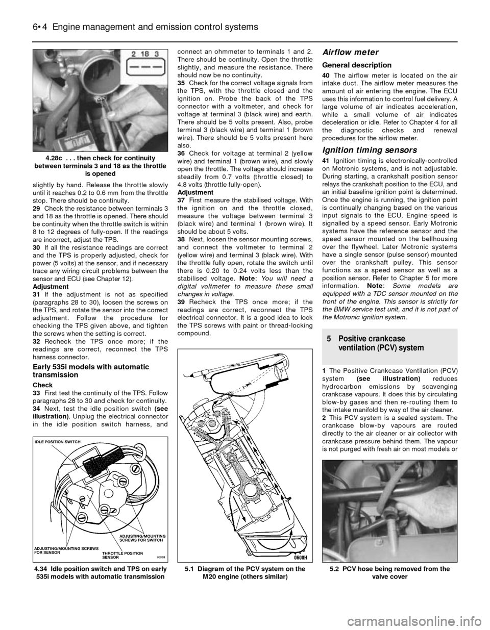
slightly by hand. Release the throttle slowly
until it reaches 0.2 to 0.6 mm from the throttle
stop. There should be continuity.
29Check the resistance between terminals 3
and 18 as the throttle is opened. There should
be continuity when the throttle switch is within
8 to 12 degrees of fully-open. If the readings
are incorrect, adjust the TPS.
30If all the resistance readings are correct
and the TPS is properly adjusted, check for
power (5 volts) at the sensor, and if necessary
trace any wiring circuit problems between the
sensor and ECU (see Chapter 12).
Adjustment
31If the adjustment is not as specified
(paragraphs 28 to 30), loosen the screws on
the TPS, and rotate the sensor into the correct
adjustment. Follow the procedure for
checking the TPS given above, and tighten
the screws when the setting is correct.
32Recheck the TPS once more; if the
readings are correct, reconnect the TPS
harness connector.
Early 535i models with automatic
transmission
Check
33First test the continuity of the TPS. Follow
paragraphs 28 to 30 and check for continuity.
34Next, test the idle position switch (see
illustration). Unplug the electrical connector
in the idle position switch harness, andconnect an ohmmeter to terminals 1 and 2.
There should be continuity. Open the throttle
slightly, and measure the resistance. There
should now be no continuity.
35Check for the correct voltage signals from
the TPS, with the throttle closed and the
ignition on. Probe the back of the TPS
connector with a voltmeter, and check for
voltage at terminal 3 (black wire) and earth.
There should be 5 volts present. Also, probe
terminal 3 (black wire) and terminal 1 (brown
wire). There should be 5 volts present here
also.
36Check for voltage at terminal 2 (yellow
wire) and terminal 1 (brown wire), and slowly
open the throttle. The voltage should increase
steadily from 0.7 volts (throttle closed) to
4.8 volts (throttle fully-open).
Adjustment
37First measure the stabilised voltage. With
the ignition on and the throttle closed,
measure the voltage between terminal 3
(black wire) and terminal 1 (brown wire). It
should be about 5 volts.
38Next, loosen the sensor mounting screws,
and connect the voltmeter to terminal 2
(yellow wire) and terminal 3 (black wire). With
the throttle fully open, rotate the switch until
there is 0.20 to 0.24 volts less than the
stabilised voltage. Note: You will need a
digital voltmeter to measure these small
changes in voltage.
39Recheck the TPS once more; if the
readings are correct, reconnect the TPS
electrical connector. It is a good idea to lock
the TPS screws with paint or thread-locking
compound.
Airflow meter
General description
40The airflow meter is located on the air
intake duct. The airflow meter measures the
amount of air entering the engine. The ECU
uses this information to control fuel delivery. A
large volume of air indicates acceleration,
while a small volume of air indicates
deceleration or idle. Refer to Chapter 4 for all
the diagnostic checks and renewal
procedures for the airflow meter.
Ignition timing sensors
41Ignition timing is electronically-controlled
on Motronic systems, and is not adjustable.
During starting, a crankshaft position sensor
relays the crankshaft position to the ECU, and
an initial baseline ignition point is determined.
Once the engine is running, the ignition point
is continually changing based on the various
input signals to the ECU. Engine speed is
signalled by a speed sensor. Early Motronic
systems have the reference sensor and the
speed sensor mounted on the bellhousing
over the flywheel. Later Motronic systems
have a single sensor (pulse sensor) mounted
over the crankshaft pulley. This sensor
functions as a speed sensor as well as a
position sensor. Refer to Chapter 5 for more
information. Note: Some models are
equipped with a TDC sensor mounted on the
front of the engine. This sensor is strictly for
the BMW service test unit, and it is not part of
the Motronic ignition system.
5 Positive crankcase
ventilation (PCV) system
1The Positive Crankcase Ventilation (PCV)
system (see illustration)reduces
hydrocarbon emissions by scavenging
crankcase vapours. It does this by circulating
blow-by gases and then re-routing them to
the intake manifold by way of the air cleaner.
2This PCV system is a sealed system. The
crankcase blow-by vapours are routed
directly to the air cleaner or air collector with
crankcase pressure behind them. The vapour
is not purged with fresh air on most models or
6•4 Engine management and emission control systems
5.2 PCV hose being removed from the
valve cover5.1 Diagram of the PCV system on the
M20 engine (others similar)4.34 Idle position switch and TPS on early
535i models with automatic transmission
4.28c . . . then check for continuity
between terminals 3 and 18 as the throttle
is opened