boot BMW 3 SERIES 1983 E30 Workshop Manual
[x] Cancel search | Manufacturer: BMW, Model Year: 1983, Model line: 3 SERIES, Model: BMW 3 SERIES 1983 E30Pages: 228, PDF Size: 7.04 MB
Page 16 of 228
1•6Maintenance and Servicing
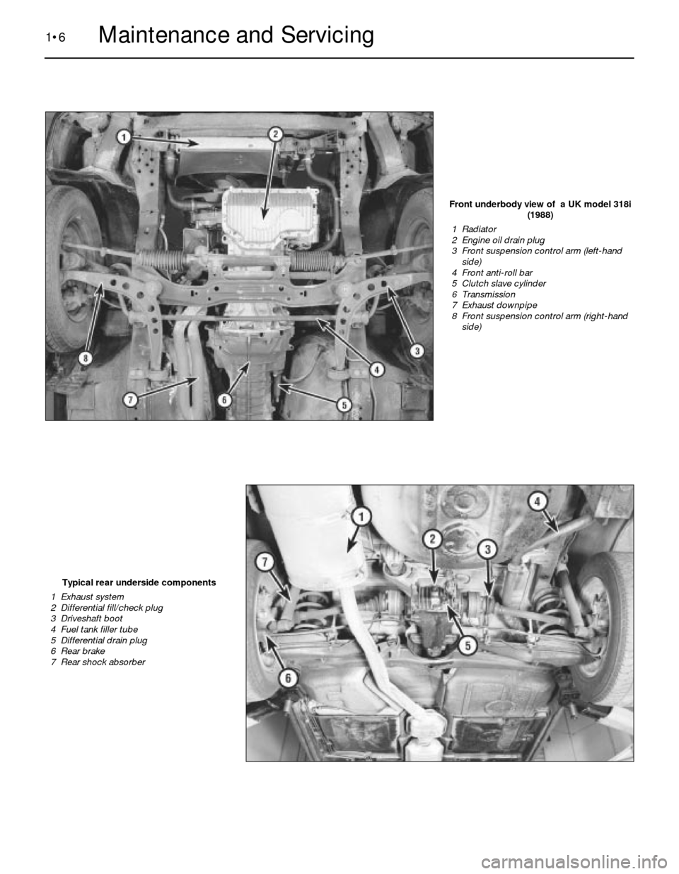
Front underbody view of a UK model 318i
(1988)
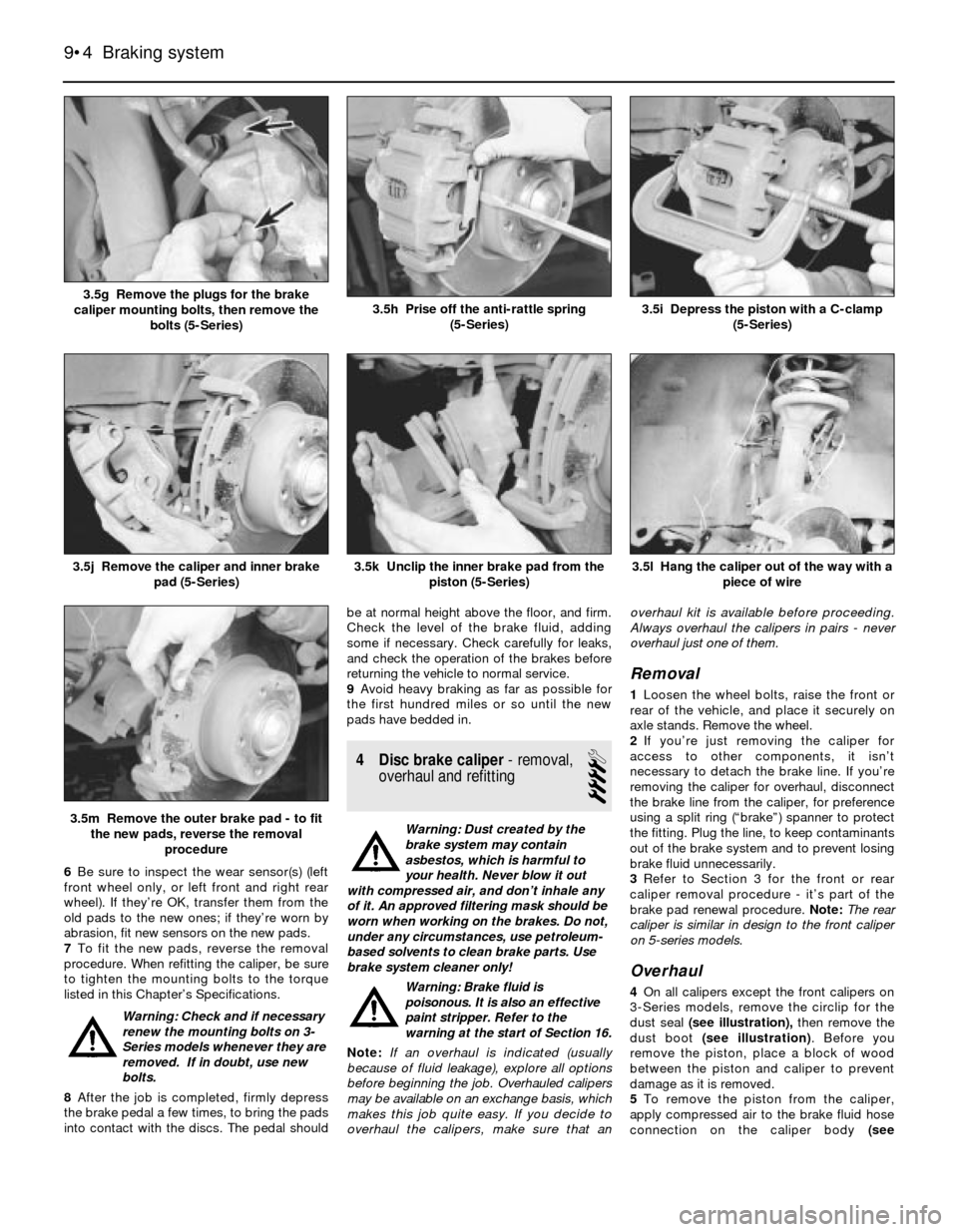
1 Radiator
2 Engine oil drain plug
3 Front suspension control arm (left-hand
side)
4 Front anti-roll bar
5 Clutch slave cylinder
6 Transmission
7 Exhaust downpipe
8 Front suspension control arm (right-hand
side)
Typical rear underside components
1 Exhaust system
2 Differential fill/check plug
3 Driveshaft boot
4 Fuel tank filler tube
5 Differential drain plug
6 Rear brake
7 Rear shock absorber
Page 32 of 228
no cause for concern. Make sure that any fluid
noted is from the struts/shocks, and not from
any other source. If leakage is noted, renew
the struts or shock absorbers in axle pairs (or
as a full set).
7Check the struts/shock absorbers to be
sure that they are securely mounted and
undamaged. Check the upper mountings for
damage and wear. If damage or wear is
noted, renew the struts or shock absorbers.
8If the struts or shock absorbers must be
renewed, refer to Chapter 10 for the
procedure. Always renew both units on the
same axle, or the safety of the vehicle may be
compromised. If possible, renew all four as a
set.
Steering and suspension check
9Inspect the steering system components
for damage and distortion. Look for leaks and
damaged seals, boots and fittings.
10Clean the lower end of the steering
knuckle. Have an assistant grasp the lower
edge of the tyre and move the wheel in and
out, while you look for movement at the
steering knuckle-to-axle arm balljoints.
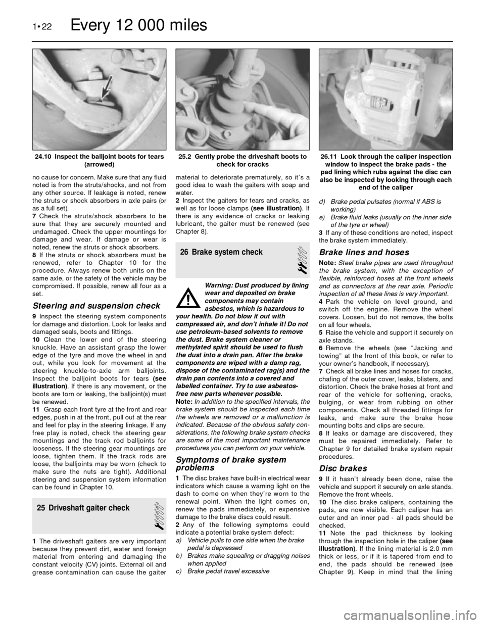
Inspect the balljoint boots for tears (see
illustration). If there is any movement, or the
boots are torn or leaking, the balljoint(s) must
be renewed.
11Grasp each front tyre at the front and rear
edges, push in at the front, pull out at the rear
and feel for play in the steering linkage. If any
free play is noted, check the steering gear
mountings and the track rod balljoints for
looseness. If the steering gear mountings are
loose, tighten them. If the track rods are
loose, the balljoints may be worn (check to
make sure the nuts are tight). Additional
steering and suspension system information
can be found in Chapter 10.
25 Driveshaft gaiter check
1
1The driveshaft gaiters are very important
because they prevent dirt, water and foreign
material from entering and damaging the
constant velocity (CV) joints. External oil and
grease contamination can cause the gaitermaterial to deteriorate prematurely, so it’s a
good idea to wash the gaiters with soap and
water.
2Inspect the gaiters for tears and cracks, as
well as for loose clamps (see illustration). If
there is any evidence of cracks or leaking
lubricant, the gaiter must be renewed (see
Chapter 8).
26 Brake system check
2
Warning: Dust produced by lining
wear and deposited on brake
components may contain
asbestos, which is hazardous to
your health. Do not blow it out with
compressed air, and don’t inhale it! Do not
use petroleum-based solvents to remove
the dust. Brake system cleaner or
methylated spirit should be used to flush
the dust into a drain pan. After the brake
components are wiped with a damp rag,
dispose of the contaminated rag(s) and the
drain pan contents into a covered and
labelled container. Try to use asbestos-
free new parts whenever possible.
Note:In addition to the specified intervals, the
brake system should be inspected each time
the wheels are removed or a malfunction is
indicated. Because of the obvious safety con-
siderations, the following brake system checks
are some of the most important maintenance
procedures you can perform on your vehicle.
Symptoms of brake system
problems
1The disc brakes have built-in electrical wear
indicators which cause a warning light on the
dash to come on when they’re worn to the
renewal point. When the light comes on,
renew the pads immediately, or expensive
damage to the brake discs could result.
2Any of the following symptoms could
indicate a potential brake system defect:
a) Vehicle pulls to one side when the brake
pedal is depressed
b) Brakes make squealing or dragging noises
when applied
c) Brake pedal travel excessived) Brake pedal pulsates (normal if ABS is
working)
e) Brake fluid leaks (usually on the inner side
of the tyre or wheel)
3If any of these conditions are noted, inspect
the brake system immediately.
Brake lines and hoses
Note: Steel brake pipes are used throughout
the brake system, with the exception of
flexible, reinforced hoses at the front wheels
and as connectors at the rear axle. Periodic
inspection of all these lines is very important.
4Park the vehicle on level ground, and
switch off the engine. Remove the wheel
covers. Loosen, but do not remove, the bolts
on all four wheels.
5Raise the vehicle and support it securely on
axle stands.
6Remove the wheels (see “Jacking and
towing” at the front of this book, or refer to
your owner’s handbook, if necessary).
7Check all brake lines and hoses for cracks,
chafing of the outer cover, leaks, blisters, and
distortion. Check the brake hoses at front and
rear of the vehicle for softening, cracks,
bulging, or wear from rubbing on other
components. Check all threaded fittings for
leaks, and make sure the brake hose
mounting bolts and clips are secure.
8If leaks or damage are discovered, they
must be repaired immediately. Refer to
Chapter 9 for detailed brake system repair
procedures.
Disc brakes
9If it hasn’t already been done, raise the
vehicle and support it securely on axle stands.
Remove the front wheels.
10The disc brake calipers, containing the
pads, are now visible. Each caliper has an
outer and an inner pad - all pads should be
checked.
11Note the pad thickness by looking
through the inspection hole in the caliper (see
illustration). If the lining material is 2.0 mm
thick or less, or if it is tapered from end to
end, the pads should be renewed (see
Chapter 9). Keep in mind that the lining
1•22
26.11 Look through the caliper inspection
window to inspect the brake pads - the
pad lining which rubs against the disc can
also be inspected by looking through each
end of the caliper25.2 Gently probe the driveshaft boots to
check for cracks24.10 Inspect the balljoint boots for tears
(arrowed)
Every 12 000 miles
Page 33 of 228
material is bonded to a metal plate or shoe -
the metal portion is not included in this
measurement. Always renew the pads on
both sides of the vehicle (in axle sets), even if
only one pad of the four is worn, or uneven
braking may result.
12Remove the calipers without
disconnecting the brake hoses (see Chap-
ter 9).
13Check the condition of the brake disc.
Look for score marks, deep scratches and
overheated areas (they will appear blue or
discoloured). If damage or wear is noted, the
disc can be removed and resurfaced by an
engineering workshop; otherwise, it will have
to be renewed. In either case, both discs
should be involved, even if only one is worn.
Refer to Chapter 9 for more detailed
inspection and repair procedures.
Drum brakes
14Refer to Chapter 9 and remove the rear
brake drums.
15Note the thickness of the lining material
on the rear brake shoes, and look for signs of
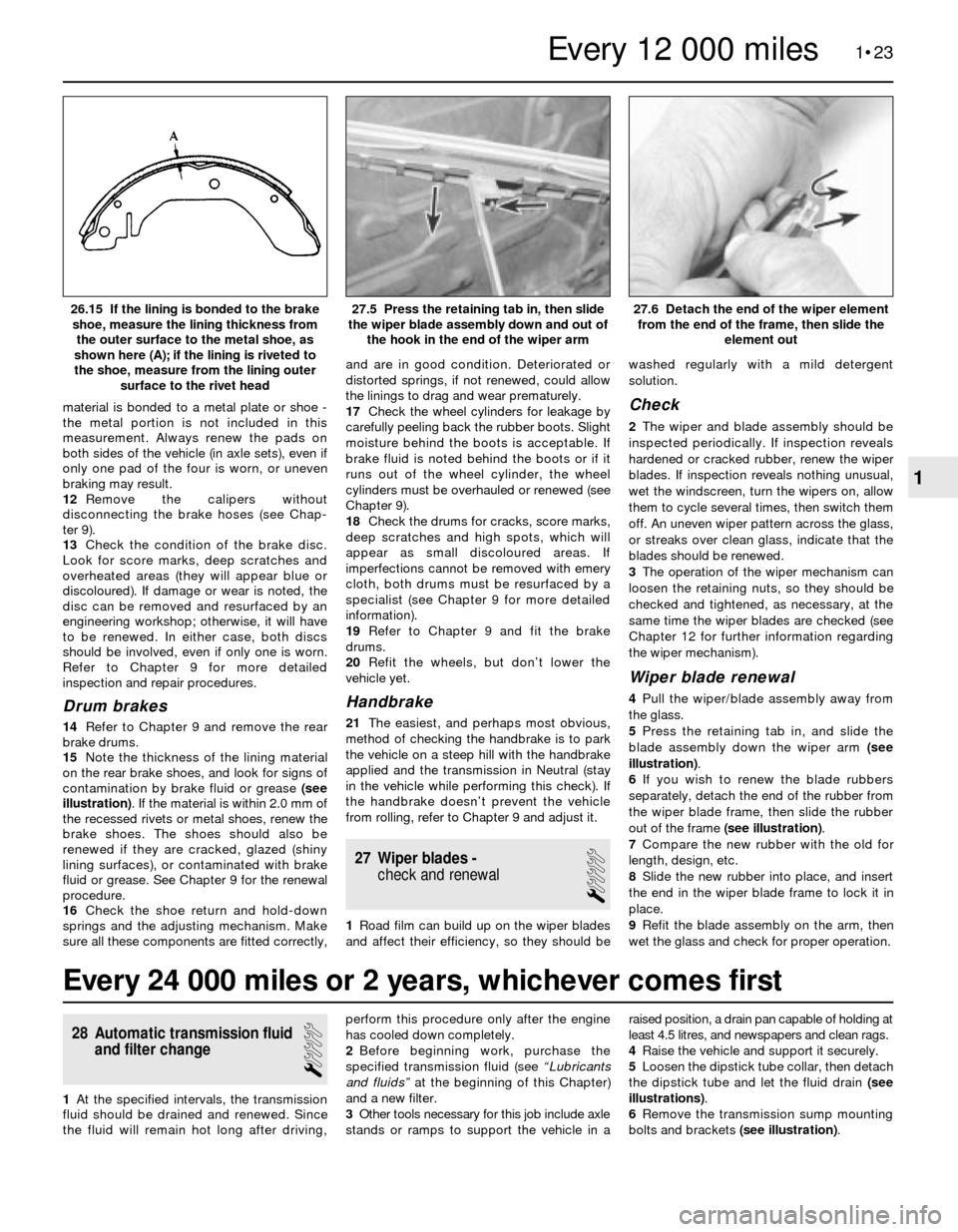
contamination by brake fluid or grease (see
illustration). If the material is within 2.0 mm of
the recessed rivets or metal shoes, renew the
brake shoes. The shoes should also be
renewed if they are cracked, glazed (shiny
lining surfaces), or contaminated with brake
fluid or grease. See Chapter 9 for the renewal
procedure.
16Check the shoe return and hold-down
springs and the adjusting mechanism. Make
sure all these components are fitted correctly,and are in good condition. Deteriorated or
distorted springs, if not renewed, could allow
the linings to drag and wear prematurely.
17Check the wheel cylinders for leakage by
carefully peeling back the rubber boots. Slight
moisture behind the boots is acceptable. If
brake fluid is noted behind the boots or if it
runs out of the wheel cylinder, the wheel
cylinders must be overhauled or renewed (see
Chapter 9).
18Check the drums for cracks, score marks,
deep scratches and high spots, which will
appear as small discoloured areas. If
imperfections cannot be removed with emery
cloth, both drums must be resurfaced by a
specialist (see Chapter 9 for more detailed
information).
19Refer to Chapter 9 and fit the brake
drums.
20Refit the wheels, but don’t lower the
vehicle yet.
Handbrake
21The easiest, and perhaps most obvious,
method of checking the handbrake is to park
the vehicle on a steep hill with the handbrake
applied and the transmission in Neutral (stay
in the vehicle while performing this check). If
the handbrake doesn’t prevent the vehicle
from rolling, refer to Chapter 9 and adjust it.
27 Wiper blades -
check and renewal
1
1Road film can build up on the wiper blades
and affect their efficiency, so they should bewashed regularly with a mild detergent
solution.
Check
2The wiper and blade assembly should be
inspected periodically. If inspection reveals
hardened or cracked rubber, renew the wiper
blades. If inspection reveals nothing unusual,
wet the windscreen, turn the wipers on, allow
them to cycle several times, then switch them
off. An uneven wiper pattern across the glass,
or streaks over clean glass, indicate that the
blades should be renewed.
3The operation of the wiper mechanism can
loosen the retaining nuts, so they should be
checked and tightened, as necessary, at the
same time the wiper blades are checked (see
Chapter 12 for further information regarding
the wiper mechanism).
Wiper blade renewal
4Pull the wiper/blade assembly away from
the glass.
5Press the retaining tab in, and slide the
blade assembly down the wiper arm (see
illustration).
6If you wish to renew the blade rubbers
separately, detach the end of the rubber from
the wiper blade frame, then slide the rubber
out of the frame (see illustration).
7Compare the new rubber with the old for
length, design, etc.
8Slide the new rubber into place, and insert
the end in the wiper blade frame to lock it in
place.
9Refit the blade assembly on the arm, then
wet the glass and check for proper operation.
1•23
27.6 Detach the end of the wiper element
from the end of the frame, then slide the
element out27.5 Press the retaining tab in, then slide
the wiper blade assembly down and out of
the hook in the end of the wiper arm26.15 If the lining is bonded to the brake
shoe, measure the lining thickness from
the outer surface to the metal shoe, as
shown here (A); if the lining is riveted to
the shoe, measure from the lining outer
surface to the rivet head
1
Every 12 000 miles
Every 24 000 miles or 2 years, whichever comes first
28 Automatic transmission fluid
and filter change
1
1At the specified intervals, the transmission
fluid should be drained and renewed. Since
the fluid will remain hot long after driving,perform this procedure only after the engine
has cooled down completely.
2Before beginning work, purchase the
specified transmission fluid (see “Lubricants
and fluids”at the beginning of this Chapter)
and a new filter.
3Other tools necessary for this job include axle
stands or ramps to support the vehicle in araised position, a drain pan capable of holding at
least 4.5 litres, and newspapers and clean rags.
4Raise the vehicle and support it securely.
5Loosen the dipstick tube collar, then detach
the dipstick tube and let the fluid drain (see
illustrations).
6Remove the transmission sump mounting
bolts and brackets (see illustration).
Page 93 of 228
19Depressurise the fuel system (see Sec-
tion 2).
20Detach the battery negative cable.
Caution: If the radio in your
vehicle is equipped with an anti-
theft system, make sure you
have the correct activation code
before disconnecting the battery. Refer to
the information on page 0-7 at the front of
this manual before detaching the cable.
Note: If, after connecting the battery, the
wrong language appears on the instrument
panel display, refer to page 0-7 for the
language resetting procedure.
21Detach the fuel feed hose from the fuel
rail, and attach a fuel pressure gauge directly
to the hose. Note:If the tee fitting is still
connected to the gauge, be sure to plug the
open end.
22Reconnect the battery.
23Using a jumper wire, bridge the terminals
of the fuel pump relay.
24Turn the ignition switch on to operate the
fuel pump.
25Note the pressure reading on the gauge,
and compare the reading to the fuel pump
pressure listed in this Chapter’s Specifica-
tions.
26If the indicated pressure is less than
specified, inspect the fuel line for leaks
between the pump and gauge. If no leaks are
found, renew the fuel pump.
27Turn the ignition off and wait five minutes.
Note the reading on the gauge, and compare
it to the fuel pump hold pressure listed in this
Chapter’s Specifications. If the hold pressure
is less than specified, check the fuel lines
between the pump and gauge for leaks. If no
leaks are found, renew the fuel pump.
28Remove the jumper wire. Relieve the fuel
pressure by opening the bleed valve on the
gauge and directing the fuel into a suitable
container. Remove the gauge and reconnect
the fuel line.
Transfer pump pressure check
29Depressurise the fuel system (see Sec-
tion 2).
30Detach the battery negative cable.
Caution: If the radio in your
vehicle is equipped with an anti-
theft system, make sure you
have the correct activation code
before disconnecting the battery. Refer to
the information on page 0-7 at the front of
this manual before detaching the cable.
Note: If, after connecting the battery, the
wrong language appears on the instrument
panel display, refer to page 0-7 for the
language resetting procedure.
31Remove the transfer pump access plate
(on some models, it’s located under the rear
seat cushion - on others, it’s located under
the carpet in the luggage compartment).
Disconnect the output hose from the transfer
pump, and connect a fuel pressure gauge to
the outlet pipe.
32Reconnect the battery.33Using a jumper wire, bridge the terminals
of the fuel pump relay.
34Turn the ignition switch on to operate the
fuel pump.
35Note the pressure reading on the gauge,
and compare to the value listed in this
Chapter’s Specifications.
36If the indicated pressure is less than
specified, renew the transfer pump.
Fuel pump relay check
37Switch on the ignition.
38Using a voltmeter, probe the following
terminals from the back of the relay electrical
connector. Check for battery voltage at
terminal 30 (M20 and M30 engines) or
terminal 15 (M10 and M40 engines). Note:If
there is no voltage on models with luggage
compartment-mounted batteries, check for a
faulty fusible link. The 50-amp link is about
6 inches from the battery, in a black wire.
39Turn the ignition off, and disconnect the
relay from the electrical connector. Using a
voltmeter, probe the connector terminals that
correspond to fuel pump relay pins 85 (-) and
86(+) on M20 and M30 engines, or terminal 50
and earth on M10 and M40 engines. Have an
assistant turn the engine over on the starter,
and observe the voltage reading. Battery
voltage should be indicated.
40If there is no voltage, check the fuse(s)
and the wiring circuit for the fuel pump relay. If
the voltage readings are correct, and the fuel
pump only runs with the jumper wire in place,
then renew the relay.
41If the fuel pump still does not run, check
for the proper voltage at the fuel pump
terminals (see Section 4). If necessary, renew
the fuel pump.
4 Fuel pump, transfer pump
and fuel level sender unit-
removal and refitting
2
Warning: Fuel is extremely
flammable, so take extra
precautions when you work on
any part of the fuel system. Don’t
smoke, or allow open flames or bare light
bulbs, near the work area. Also, don’t work
in a garage where a natural gas-type
appliance with a pilot light is present.
Fuel pump (carburettor engines)
1Disconnect the battery negative cable.
Disconnect both hoses from the pump, and
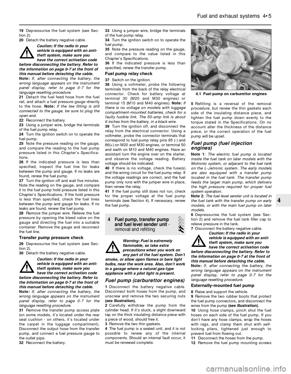
unscrew and remove the two securing nuts
(see illustration).
2Carefully withdraw the pump from the
cylinder head. If it’s stuck, a slight downward
tap on the thick insulating distance piece with
a piece of wood, should free it.
3Remove the two thin gaskets.
4The fuel pump is a sealed unit, and it is not
possible to renew any of the internal
components. Should an internal fault occur, it
must be renewed complete.5Refitting is a reversal of the removal
procedure, but renew the thin gaskets each
side of the insulating distance piece, and
tighten the fuel pump down evenly to the
torque stated in the Specifications. On no
account alter the thickness of the distance
piece, or the correct operation of the fuel
pump will be upset.
Fuel pump (fuel injection
engines)
Note 1: The electric fuel pump is located
inside the fuel tank on later models with the
Motronic system, or adjacent to the fuel tank
on the L-Jetronic system. The early models
are also equipped with a transfer pump
located in the fuel tank. The transfer pump
feeds the larger main pump, which delivers
the high pressure required for proper fuel
system operation.
Note 2: The fuel level sender unit is located in
the fuel tank with the transfer pump on early
models, or with the main fuel pump on later
models.
6Depressurise the fuel system (see Sec-
tion 2) and remove the fuel tank filler cap to
relieve pressure in the tank.
7Disconnect the battery negative cable.
Caution: If the radio in your
vehicle is equipped with an anti-
theft system, make sure you
have the correct activation code
before disconnecting the battery. Refer to
the information on page 0-7 at the front of
this manual before detaching the cable.
Note: If, after connecting the battery, the
wrong language appears on the instrument
panel display, refer to page 0-7 for the
language resetting procedure.
Externally-mounted fuel pump
8Raise and support the vehicle.
9Remove the two rubber boots that protect
the fuel pump connectors, and disconnect the
wires from the pump (see illustration).
10Using hose clamps, pinch shut the fuel
hoses on each side of the fuel pump. If you
don’t have any hose clamps, wrap the hoses
with rags, and clamp them shut with self-
locking pliers, tightened just enough to
prevent fuel from flowing out.
11Disconnect the hoses from the pump.
12Remove the fuel pump mounting screws
Fuel and exhaust systems 4•5
4.1 Fuel pump on carburettor engines
4
Page 94 of 228
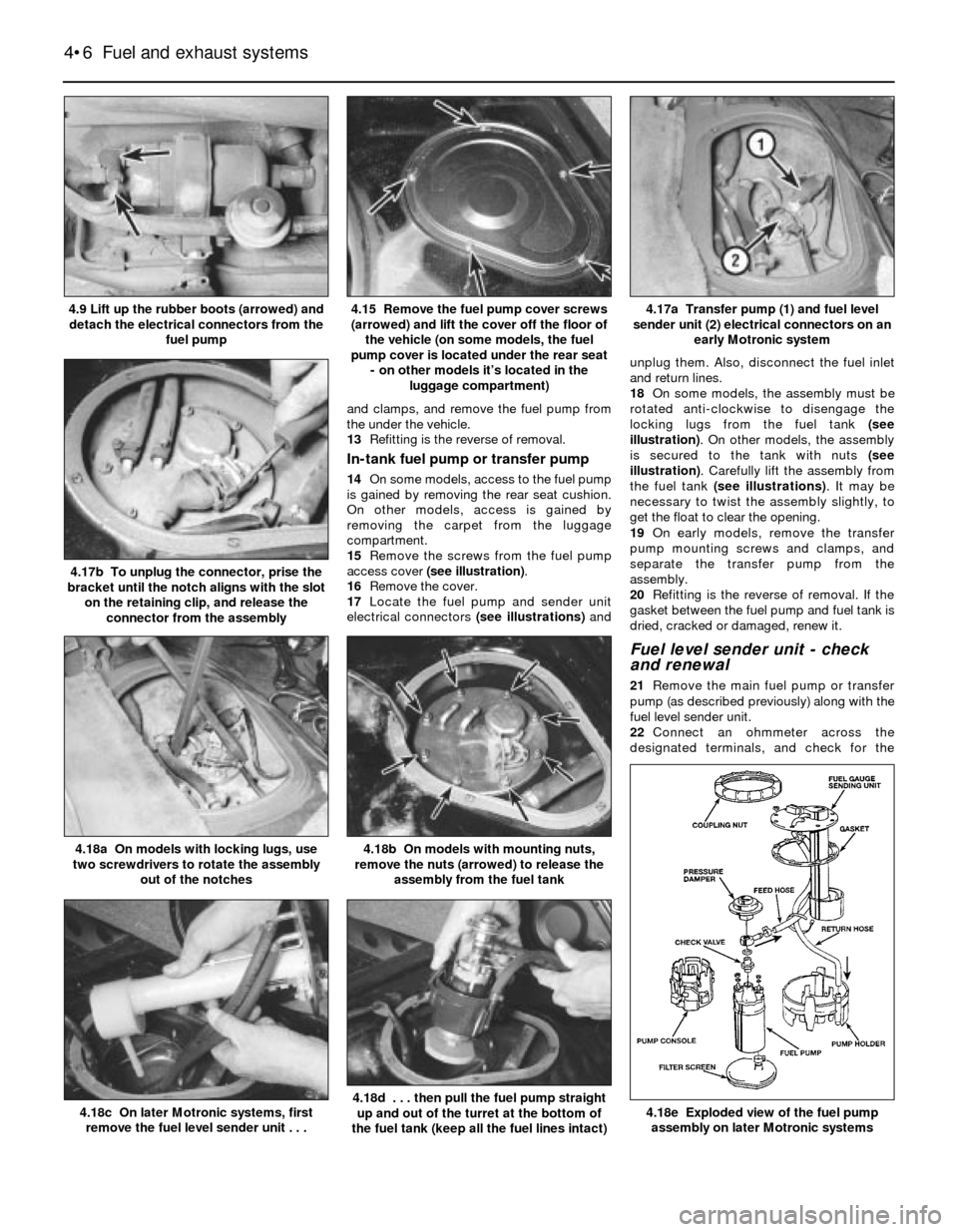
and clamps, and remove the fuel pump from
the under the vehicle.
13Refitting is the reverse of removal.
In-tank fuel pump or transfer pump
14On some models, access to the fuel pump
is gained by removing the rear seat cushion.
On other models, access is gained by
removing the carpet from the luggage
compartment.
15Remove the screws from the fuel pump
access cover (see illustration).
16Remove the cover.
17Locate the fuel pump and sender unit
electrical connectors (see illustrations)andunplug them. Also, disconnect the fuel inlet
and return lines.
18On some models, the assembly must be
rotated anti-clockwise to disengage the
locking lugs from the fuel tank (see
illustration). On other models, the assembly
is secured to the tank with nuts (see
illustration). Carefully lift the assembly from
the fuel tank (see illustrations). It may be
necessary to twist the assembly slightly, to
get the float to clear the opening.
19On early models, remove the transfer
pump mounting screws and clamps, and
separate the transfer pump from the
assembly.
20Refitting is the reverse of removal. If the
gasket between the fuel pump and fuel tank is
dried, cracked or damaged, renew it.
Fuel level sender unit - check
and renewal
21Remove the main fuel pump or transfer
pump (as described previously) along with the
fuel level sender unit.
22Connect an ohmmeter across the
designated terminals, and check for the
4•6 Fuel and exhaust systems
4.18e Exploded view of the fuel pump
assembly on later Motronic systems4.18d . . . then pull the fuel pump straight
up and out of the turret at the bottom of
the fuel tank (keep all the fuel lines intact)4.18c On later Motronic systems, first
remove the fuel level sender unit . . .
4.18b On models with mounting nuts,
remove the nuts (arrowed) to release the
assembly from the fuel tank4.18a On models with locking lugs, use
two screwdrivers to rotate the assembly
out of the notches
4.17b To unplug the connector, prise the
bracket until the notch aligns with the slot
on the retaining clip, and release the
connector from the assembly
4.17a Transfer pump (1) and fuel level
sender unit (2) electrical connectors on an
early Motronic system4.15 Remove the fuel pump cover screws
(arrowed) and lift the cover off the floor of
the vehicle (on some models, the fuel
pump cover is located under the rear seat
- on other models it’s located in the
luggage compartment)4.9 Lift up the rubber boots (arrowed) and
detach the electrical connectors from the
fuel pump
Page 105 of 228
gauge to the pressure regulator vacuum hose,
and check for vacuum (engine idling).
11If there is vacuum present, renew the fuel
pressure regulator.
12If there isn’t any reading on the gauge,
check the hose and its port for a leak or a
restriction.
Renewal
13Depressurise the fuel system (see Sec-
tion 2).
14Detach the battery negative cable.
Caution: If the radio in your
vehicle is equipped with an anti-
theft system, make sure you
have the correct activation code
before disconnecting the battery. Refer to
the information on page 0-7 at the front of
this manual before detaching the cable.
Note: If, after connecting the battery, the
wrong language appears on the instrument
panel display, refer to page 0-7 for the
language resetting procedure.
15Detach the vacuum hose and fuel return
hose from the pressure regulator, then
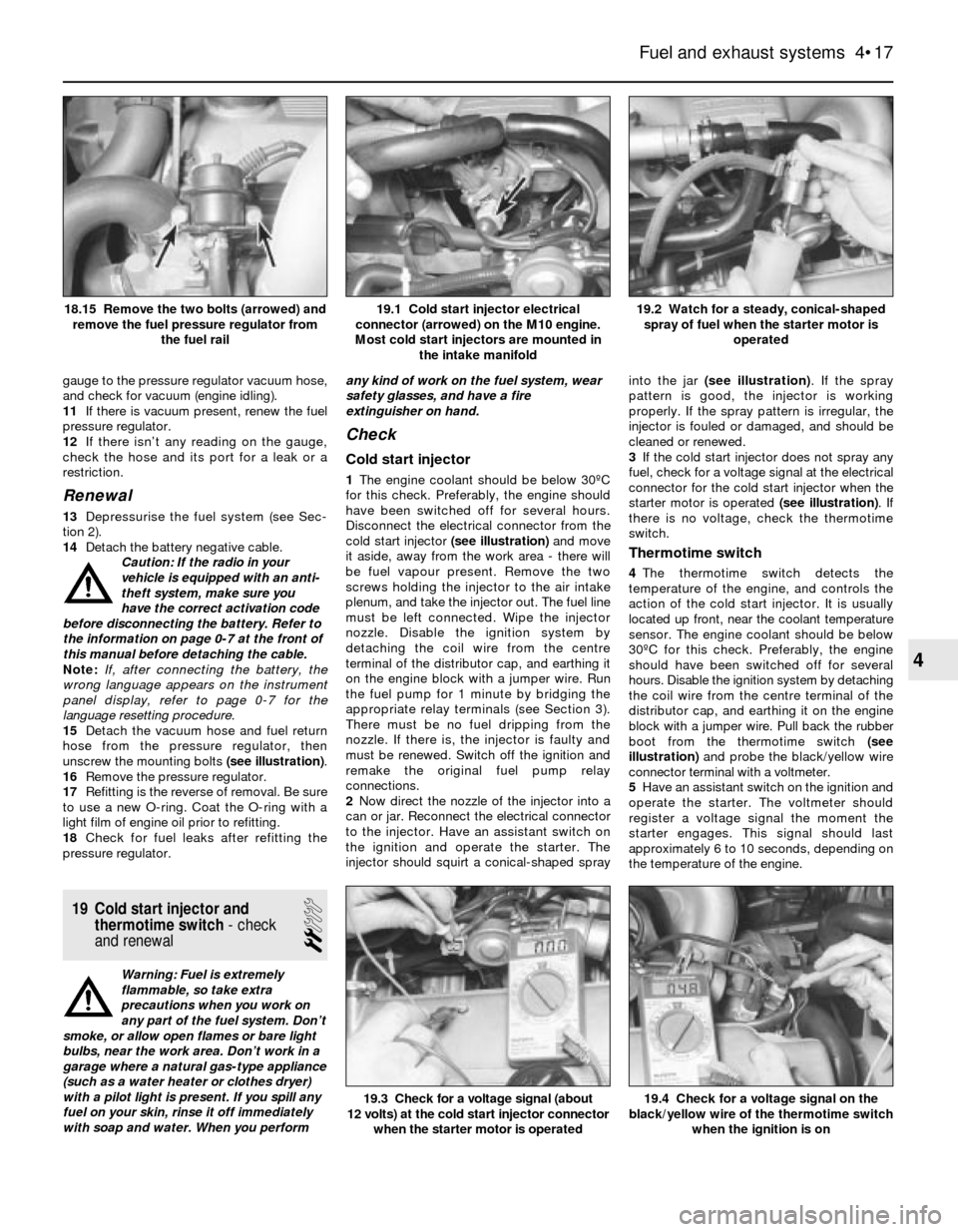
unscrew the mounting bolts (see illustration).
16Remove the pressure regulator.
17Refitting is the reverse of removal. Be sure
to use a new O-ring. Coat the O-ring with a
light film of engine oil prior to refitting.
18Check for fuel leaks after refitting the
pressure regulator.
19 Cold start injector and
thermotime switch- check
and renewal
2
Warning: Fuel is extremely
flammable, so take extra
precautions when you work on
any part of the fuel system. Don’t
smoke, or allow open flames or bare light
bulbs, near the work area. Don’t work in a
garage where a natural gas-type appliance
(such as a water heater or clothes dryer)
with a pilot light is present. If you spill any
fuel on your skin, rinse it off immediately
with soap and water. When you performany kind of work on the fuel system, wear
safety glasses, and have a fire
extinguisher on hand.
Check
Cold start injector
1The engine coolant should be below 30ºC
for this check. Preferably, the engine should
have been switched off for several hours.
Disconnect the electrical connector from the
cold start injector (see illustration)and move
it aside, away from the work area - there will
be fuel vapour present. Remove the two
screws holding the injector to the air intake
plenum, and take the injector out. The fuel line
must be left connected. Wipe the injector
nozzle. Disable the ignition system by
detaching the coil wire from the centre
terminal of the distributor cap, and earthing it
on the engine block with a jumper wire. Run
the fuel pump for 1 minute by bridging the
appropriate relay terminals (see Section 3).
There must be no fuel dripping from the
nozzle. If there is, the injector is faulty and
must be renewed. Switch off the ignition and
remake the original fuel pump relay
connections.
2Now direct the nozzle of the injector into a
can or jar. Reconnect the electrical connector
to the injector. Have an assistant switch on
the ignition and operate the starter. The
injector should squirt a conical-shaped sprayinto the jar (see illustration). If the spray
pattern is good, the injector is working
properly. If the spray pattern is irregular, the
injector is fouled or damaged, and should be
cleaned or renewed.
3If the cold start injector does not spray any
fuel, check for a voltage signal at the electrical
connector for the cold start injector when the
starter motor is operated (see illustration). If
there is no voltage, check the thermotime
switch.
Thermotime switch
4The thermotime switch detects the
temperature of the engine, and controls the
action of the cold start injector. It is usually
located up front, near the coolant temperature
sensor. The engine coolant should be below
30ºC for this check. Preferably, the engine
should have been switched off for several
hours. Disable the ignition system by detaching
the coil wire from the centre terminal of the
distributor cap, and earthing it on the engine
block with a jumper wire. Pull back the rubber
boot from the thermotime switch (see
illustration)and probe the black/yellow wire
connector terminal with a voltmeter.
5Have an assistant switch on the ignition and
operate the starter. The voltmeter should
register a voltage signal the moment the
starter engages. This signal should last
approximately 6 to 10 seconds, depending on
the temperature of the engine.
Fuel and exhaust systems 4•17
19.2 Watch for a steady, conical-shaped
spray of fuel when the starter motor is
operated19.1 Cold start injector electrical
connector (arrowed) on the M10 engine.
Most cold start injectors are mounted in
the intake manifold18.15 Remove the two bolts (arrowed) and
remove the fuel pressure regulator from
the fuel rail
19.4 Check for a voltage signal on the
black/yellow wire of the thermotime switch
when the ignition is on19.3 Check for a voltage signal (about
12 volts) at the cold start injector connector
when the starter motor is operated
4
Page 124 of 228
4 Information sensors
2
Note:Refer to Chapters 4 and 5 for additional
information on the location and diagnosis of
the information sensors that are not covered in
this Section.
Coolant temperature sensor
General description
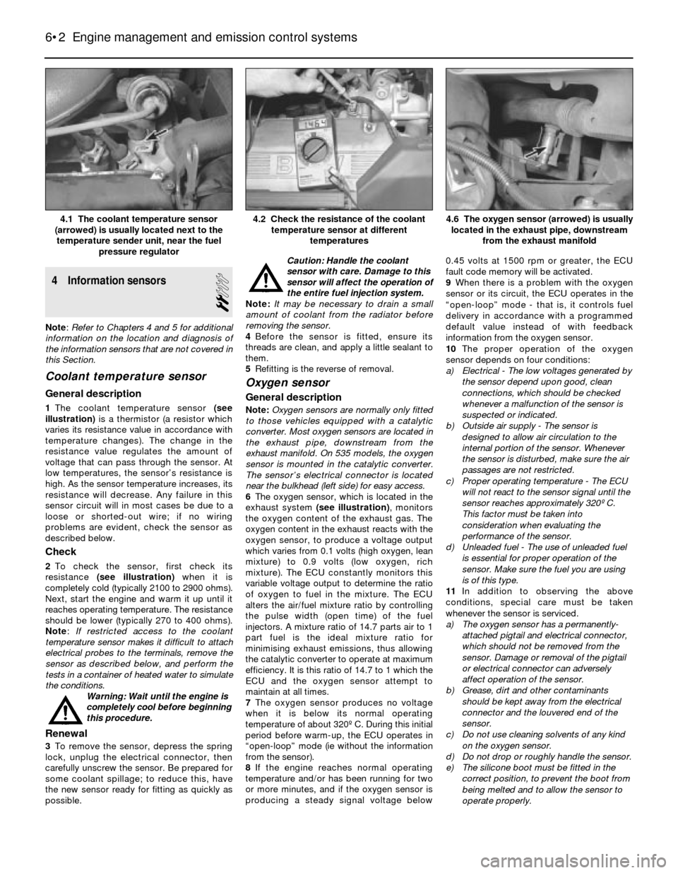
1The coolant temperature sensor (see
illustration)is a thermistor (a resistor which
varies its resistance value in accordance with
temperature changes). The change in the
resistance value regulates the amount of
voltage that can pass through the sensor. At
low temperatures, the sensor’s resistance is
high. As the sensor temperature increases, its
resistance will decrease. Any failure in this
sensor circuit will in most cases be due to a
loose or shorted-out wire; if no wiring
problems are evident, check the sensor as
described below.
Check
2To check the sensor, first check its
resistance (see illustration)when it is
completely cold (typically 2100 to 2900 ohms).
Next, start the engine and warm it up until it
reaches operating temperature. The resistance
should be lower (typically 270 to 400 ohms).
Note: If restricted access to the coolant
temperature sensor makes it difficult to attach
electrical probes to the terminals, remove the
sensor as described below, and perform the
tests in a container of heated water to simulate
the conditions.
Warning: Wait until the engine is
completely cool before beginning
this procedure.
Renewal
3To remove the sensor, depress the spring
lock, unplug the electrical connector, then
carefully unscrew the sensor. Be prepared for
some coolant spillage; to reduce this, have
the new sensor ready for fitting as quickly as
possible.Caution: Handle the coolant
sensor with care. Damage to this
sensor will affect the operation of
the entire fuel injection system.
Note: It may be necessary to drain a small
amount of coolant from the radiator before
removing the sensor.
4Before the sensor is fitted, ensure its
threads are clean, and apply a little sealant to
them.
5Refitting is the reverse of removal.
Oxygen sensor
General description
Note:Oxygen sensors are normally only fitted
to those vehicles equipped with a catalytic
converter. Most oxygen sensors are located in
the exhaust pipe, downstream from the
exhaust manifold. On 535 models, the oxygen
sensor is mounted in the catalytic converter.
The sensor’s electrical connector is located
near the bulkhead (left side) for easy access.
6The oxygen sensor, which is located in the
exhaust system (see illustration), monitors
the oxygen content of the exhaust gas. The
oxygen content in the exhaust reacts with the
oxygen sensor, to produce a voltage output
which varies from 0.1 volts (high oxygen, lean
mixture) to 0.9 volts (low oxygen, rich
mixture). The ECU constantly monitors this
variable voltage output to determine the ratio
of oxygen to fuel in the mixture. The ECU
alters the air/fuel mixture ratio by controlling
the pulse width (open time) of the fuel
injectors. A mixture ratio of 14.7 parts air to 1
part fuel is the ideal mixture ratio for
minimising exhaust emissions, thus allowing
the catalytic converter to operate at maximum
efficiency. It is this ratio of 14.7 to 1 which the
ECU and the oxygen sensor attempt to
maintain at all times.
7The oxygen sensor produces no voltage
when it is below its normal operating
temperature of about 320º C. During this initial
period before warm-up, the ECU operates in
“open-loop” mode (ie without the information
from the sensor).
8If the engine reaches normal operating
temperature and/or has been running for two
or more minutes, and if the oxygen sensor is
producing a steady signal voltage below 0.45 volts at 1500 rpm or greater, the ECU
fault code memory will be activated.
9When there is a problem with the oxygen
sensor or its circuit, the ECU operates in the
“open-loop” mode - that is, it controls fuel
delivery in accordance with a programmed
default value instead of with feedback
information from the oxygen sensor.
10The proper operation of the oxygen
sensor depends on four conditions:
a) Electrical - The low voltages generated by
the sensor depend upon good, clean
connections, which should be checked
whenever a malfunction of the sensor is
suspected or indicated.
b) Outside air supply - The sensor is
designed to allow air circulation to the
internal portion of the sensor. Whenever
the sensor is disturbed, make sure the air
passages are not restricted.
c) Proper operating temperature - The ECU
will not react to the sensor signal until the
sensor reaches approximately 320º C.
This factor must be taken into
consideration when evaluating the
performance of the sensor.
d) Unleaded fuel - The use of unleaded fuel
is essential for proper operation of the
sensor. Make sure the fuel you are using
is of this type.
11In addition to observing the above
conditions, special care must be taken
whenever the sensor is serviced.
a) The oxygen sensor has a permanently-
attached pigtail and electrical connector,
which should not be removed from the
sensor. Damage or removal of the pigtail
or electrical connector can adversely
affect operation of the sensor.
b) Grease, dirt and other contaminants
should be kept away from the electrical
connector and the louvered end of the
sensor.
c) Do not use cleaning solvents of any kind
on the oxygen sensor.
d) Do not drop or roughly handle the sensor.
e) The silicone boot must be fitted in the
correct position, to prevent the boot from
being melted and to allow the sensor to
operate properly.
6•2 Engine management and emission control systems
4.6 The oxygen sensor (arrowed) is usually
located in the exhaust pipe, downstream
from the exhaust manifold4.2 Check the resistance of the coolant
temperature sensor at different
temperatures4.1 The coolant temperature sensor
(arrowed) is usually located next to the
temperature sender unit, near the fuel
pressure regulator
Page 125 of 228
Check
12Warm up the engine, and let it run at idle.
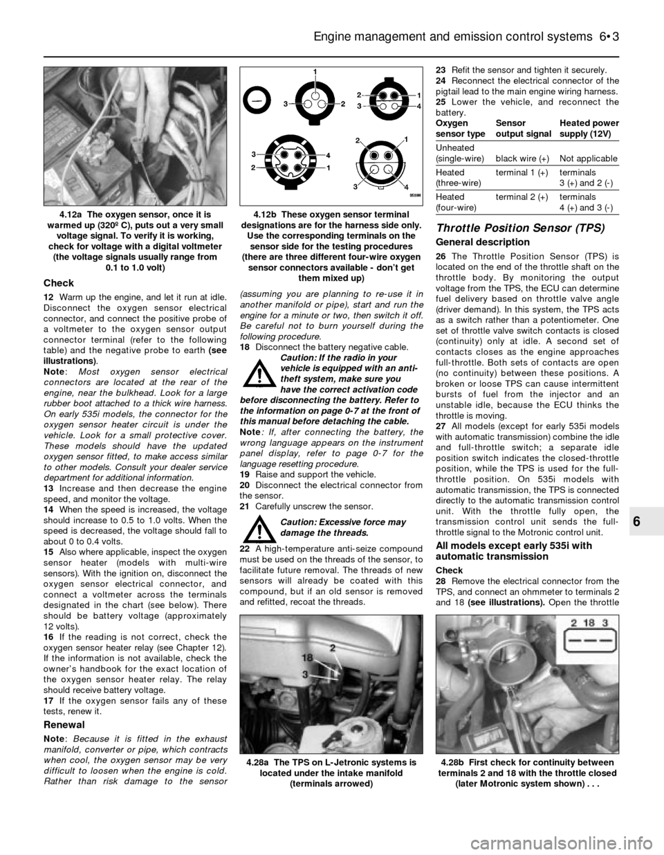
Disconnect the oxygen sensor electrical
connector, and connect the positive probe of
a voltmeter to the oxygen sensor output
connector terminal (refer to the following
table) and the negative probe to earth (see
illustrations).
Note:Most oxygen sensor electrical
connectors are located at the rear of the
engine, near the bulkhead. Look for a large
rubber boot attached to a thick wire harness.
On early 535i models, the connector for the
oxygen sensor heater circuit is under the
vehicle. Look for a small protective cover.
These models should have the updated
oxygen sensor fitted, to make access similar
to other models. Consult your dealer service
department for additional information.
13Increase and then decrease the engine
speed, and monitor the voltage.
14When the speed is increased, the voltage
should increase to 0.5 to 1.0 volts. When the
speed is decreased, the voltage should fall to
about 0 to 0.4 volts.
15Also where applicable, inspect the oxygen
sensor heater (models with multi-wire
sensors). With the ignition on, disconnect the
oxygen sensor electrical connector, and
connect a voltmeter across the terminals
designated in the chart (see below). There
should be battery voltage (approximately
12 volts).
16If the reading is not correct, check the
oxygen sensor heater relay (see Chapter 12).
If the information is not available, check the
owner’s handbook for the exact location of
the oxygen sensor heater relay. The relay
should receive battery voltage.
17If the oxygen sensor fails any of these
tests, renew it.
Renewal
Note: Because it is fitted in the exhaust
manifold, converter or pipe, which contracts
when cool, the oxygen sensor may be very
difficult to loosen when the engine is cold.
Rather than risk damage to the sensor(assuming you are planning to re-use it in
another manifold or pipe), start and run the
engine for a minute or two, then switch it off.
Be careful not to burn yourself during the
following procedure.
18Disconnect the battery negative cable.
Caution: If the radio in your
vehicle is equipped with an anti-
theft system, make sure you
have the correct activation code
before disconnecting the battery. Refer to
the information on page 0-7 at the front of
this manual before detaching the cable.
Note: If, after connecting the battery, the
wrong language appears on the instrument
panel display, refer to page 0-7 for the
language resetting procedure.
19Raise and support the vehicle.
20Disconnect the electrical connector from
the sensor.
21Carefully unscrew the sensor.
Caution: Excessive force may
damage the threads.
22A high-temperature anti-seize compound
must be used on the threads of the sensor, to
facilitate future removal. The threads of new
sensors will already be coated with this
compound, but if an old sensor is removed
and refitted, recoat the threads.23Refit the sensor and tighten it securely.
24Reconnect the electrical connector of the
pigtail lead to the main engine wiring harness.
25Lower the vehicle, and reconnect the
battery.
Oxygen Sensor Heated power
sensor type output signal supply (12V)
Unheated
(single-wire) black wire (+) Not applicable
Heated terminal 1 (+) terminals
(three-wire) 3 (+) and 2 (-)
Heated terminal 2 (+) terminals
(four-wire) 4 (+) and 3 (-)
Throttle Position Sensor (TPS)
General description
26The Throttle Position Sensor (TPS) is
located on the end of the throttle shaft on the
throttle body. By monitoring the output
voltage from the TPS, the ECU can determine
fuel delivery based on throttle valve angle
(driver demand). In this system, the TPS acts
as a switch rather than a potentiometer. One
set of throttle valve switch contacts is closed
(continuity) only at idle. A second set of
contacts closes as the engine approaches
full-throttle. Both sets of contacts are open
(no continuity) between these positions. A
broken or loose TPS can cause intermittent
bursts of fuel from the injector and an
unstable idle, because the ECU thinks the
throttle is moving.
27All models (except for early 535i models
with automatic transmission) combine the idle
and full-throttle switch; a separate idle
position switch indicates the closed-throttle
position, while the TPS is used for the full-
throttle position. On 535i models with
automatic transmission, the TPS is connected
directly to the automatic transmission control
unit. With the throttle fully open, the
transmission control unit sends the full-
throttle signal to the Motronic control unit.
All models except early 535i with
automatic transmission
Check
28Remove the electrical connector from the
TPS, and connect an ohmmeter to terminals 2
and 18 (see illustrations). Open the throttle
Engine management and emission control systems 6•3
4.12b These oxygen sensor terminal
designations are for the harness side only.
Use the corresponding terminals on the
sensor side for the testing procedures
(there are three different four-wire oxygen
sensor connectors available - don’t get
them mixed up)4.12a The oxygen sensor, once it is
warmed up (320º C), puts out a very small
voltage signal. To verify it is working,
check for voltage with a digital voltmeter
(the voltage signals usually range from
0.1 to 1.0 volt)
4.28b First check for continuity between
terminals 2 and 18 with the throttle closed
(later Motronic system shown) . . .4.28a The TPS on L-Jetronic systems is
located under the intake manifold
(terminals arrowed)
6
Page 132 of 228
6Be sure to inspect the wear sensor(s) (left
front wheel only, or left front and right rear
wheel). If they’re OK, transfer them from the
old pads to the new ones; if they’re worn by
abrasion, fit new sensors on the new pads.
7To fit the new pads, reverse the removal
procedure. When refitting the caliper, be sure
to tighten the mounting bolts to the torque
listed in this Chapter’s Specifications.
Warning: Check and if necessary
renew the mounting bolts on 3-
Series models whenever they are
removed. If in doubt, use new
bolts.
8After the job is completed, firmly depress
the brake pedal a few times, to bring the pads
into contact with the discs. The pedal shouldbe at normal height above the floor, and firm.
Check the level of the brake fluid, adding
some if necessary. Check carefully for leaks,
and check the operation of the brakes before
returning the vehicle to normal service.
9Avoid heavy braking as far as possible for
the first hundred miles or so until the new
pads have bedded in.
4 Disc brake caliper- removal,
overhaul and refitting
4
Warning: Dust created by the
brake system may contain
asbestos, which is harmful to
your health. Never blow it out
with compressed air, and don’t inhale any
of it. An approved filtering mask should be
worn when working on the brakes. Do not,
under any circumstances, use petroleum-
based solvents to clean brake parts. Use
brake system cleaner only!
Warning: Brake fluid is
poisonous. It is also an effective
paint stripper. Refer to the
warning at the start of Section 16.
Note:If an overhaul is indicated (usually
because of fluid leakage), explore all options
before beginning the job. Overhauled calipers
may be available on an exchange basis, which
makes this job quite easy. If you decide to
overhaul the calipers, make sure that anoverhaul kit is available before proceeding.
Always overhaul the calipers in pairs - never
overhaul just one of them.
Removal
1Loosen the wheel bolts, raise the front or
rear of the vehicle, and place it securely on
axle stands. Remove the wheel.
2If you’re just removing the caliper for
access to other components, it isn’t
necessary to detach the brake line. If you’re
removing the caliper for overhaul, disconnect
the brake line from the caliper, for preference
using a split ring (“brake”) spanner to protect
the fitting. Plug the line, to keep contaminants
out of the brake system and to prevent losing
brake fluid unnecessarily.
3Refer to Section 3 for the front or rear
caliper removal procedure - it’s part of the
brake pad renewal procedure. Note:The rear
caliper is similar in design to the front caliper
on 5-series models.
Overhaul
4On all calipers except the front calipers on
3-Series models, remove the circlip for the
dust seal (see illustration),then remove the
dust boot (see illustration). Before you
remove the piston, place a block of wood
between the piston and caliper to prevent
damage as it is removed.
5To remove the piston from the caliper,
apply compressed air to the brake fluid hose
connection on the caliper body (see
9•4 Braking system
3.5l Hang the caliper out of the way with a
piece of wire
3.5m Remove the outer brake pad - to fit
the new pads, reverse the removal
procedure
3.5k Unclip the inner brake pad from the
piston (5-Series)3.5j Remove the caliper and inner brake
pad (5-Series)
3.5i Depress the piston with a C-clamp
(5-Series)3.5h Prise off the anti-rattle spring
(5-Series)3.5g Remove the plugs for the brake
caliper mounting bolts, then remove the
bolts (5-Series)
Page 133 of 228
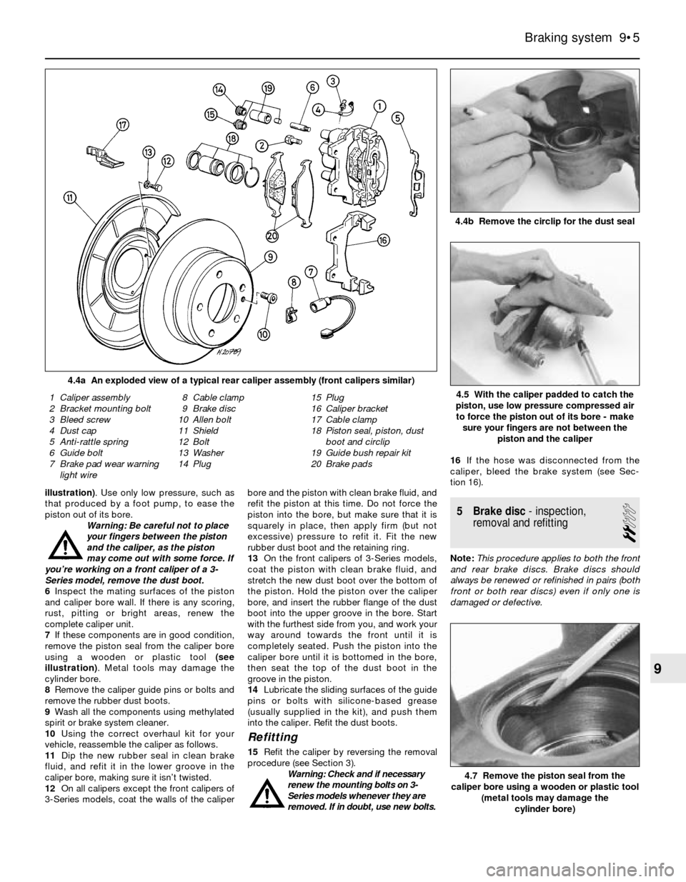
illustration). Use only low pressure, such as
that produced by a foot pump, to ease the
piston out of its bore.
Warning: Be careful not to place
your fingers between the piston
and the caliper, as the piston
may come out with some force. If
you’re working on a front caliper of a 3-
Series model, remove the dust boot.
6Inspect the mating surfaces of the piston
and caliper bore wall. If there is any scoring,
rust, pitting or bright areas, renew the
complete caliper unit.
7If these components are in good condition,
remove the piston seal from the caliper bore
using a wooden or plastic tool (see
illustration). Metal tools may damage the
cylinder bore.
8Remove the caliper guide pins or bolts and
remove the rubber dust boots.
9Wash all the components using methylated
spirit or brake system cleaner.
10Using the correct overhaul kit for your
vehicle, reassemble the caliper as follows.
11Dip the new rubber seal in clean brake
fluid, and refit it in the lower groove in the
caliper bore, making sure it isn’t twisted.
12On all calipers except the front calipers of
3-Series models, coat the walls of the caliperbore and the piston with clean brake fluid, and
refit the piston at this time. Do not force the
piston into the bore, but make sure that it is
squarely in place, then apply firm (but not
excessive) pressure to refit it. Fit the new
rubber dust boot and the retaining ring.
13On the front calipers of 3-Series models,
coat the piston with clean brake fluid, and
stretch the new dust boot over the bottom of
the piston. Hold the piston over the caliper
bore, and insert the rubber flange of the dust
boot into the upper groove in the bore. Start
with the furthest side from you, and work your
way around towards the front until it is
completely seated. Push the piston into the
caliper bore until it is bottomed in the bore,
then seat the top of the dust boot in the
groove in the piston.
14Lubricate the sliding surfaces of the guide
pins or bolts with silicone-based grease
(usually supplied in the kit), and push them
into the caliper. Refit the dust boots.
Refitting
15Refit the caliper by reversing the removal
procedure (see Section 3).
Warning: Check and if necessary
renew the mounting bolts on 3-
Series models whenever they are
removed. If in doubt, use new bolts.16If the hose was disconnected from the
caliper, bleed the brake system (see Sec-
tion 16).
5 Brake disc- inspection,
removal and refitting
2
Note:This procedure applies to both the front
and rear brake discs. Brake discs should
always be renewed or refinished in pairs (both
front or both rear discs) even if only one is
damaged or defective.
Braking system 9•5
4.4b Remove the circlip for the dust seal
4.4a An exploded view of a typical rear caliper assembly (front calipers similar)
4.7 Remove the piston seal from the
caliper bore using a wooden or plastic tool
(metal tools may damage the
cylinder bore)
1 Caliper assembly
2 Bracket mounting bolt
3 Bleed screw
4 Dust cap
5 Anti-rattle spring
6 Guide bolt
7 Brake pad wear warning
light wire8 Cable clamp
9 Brake disc
10 Allen bolt
11 Shield
12 Bolt
13 Washer
14 Plug15 Plug
16 Caliper bracket
17 Cable clamp
18 Piston seal, piston, dust
boot and circlip
19 Guide bush repair kit
20 Brake pads4.5 With the caliper padded to catch the
piston, use low pressure compressed air
to force the piston out of its bore - make
sure your fingers are not between the
piston and the caliper
9