key BMW 3 SERIES 1983 E30 Workshop Manual
[x] Cancel search | Manufacturer: BMW, Model Year: 1983, Model line: 3 SERIES, Model: BMW 3 SERIES 1983 E30Pages: 228, PDF Size: 7.04 MB
Page 25 of 228
move the component away from the engine to
tighten the belt, or towards the engine to
loosen the belt. Hold the accessory in
position, and check the belt tension. If it is
correct, tighten the two bolts until just tight,
then recheck the tension. If the tension is still
correct, tighten the bolts.
8It will often be necessary to use some sort
of lever to move the accessory while the belt
is adjusted. If this must be done to gain the
proper leverage, be very careful not to
damage the component being moved, or the
part being prised against.
Renewal
9To renew a belt, follow the instructions
above for adjustment, but remove the belt
from the pulleys.
10In some cases, you will have to remove
more than one belt, because of their
arrangement on the front of the engine.
Because of this, and the fact that belts will
tend to fail at the same time, it is wise to
renew all belts together. Mark each belt and
its appropriate pulley groove, so all renewed
belts can be fitted in their proper positions.
11It is a good idea to take the old belts with
you when buying new ones, in order to make
a direct comparison for length, width and
design.
12Recheck the tension of new belts after a
few hundred miles.
12 Engine idle speed and CO
level check and adjustment
4
Note:The engine should be at normal
operating temperature, with correct ignition
timing and valve clearances (where
adjustable). The air filter should be in good
condition, and all electrical components
(including the air conditioning, where fitted)
should be switched off.
Carburettor
1Connect a tachometer and exhaust gas
analyser (CO meter) to the engine.
2Start the engine and allow it to idle.
3Check that the idle speed is as given in the
Specifications. Adjustment of the idle speed is
only possible on the 2B4 carburettor. Turn the
carburettor idle speed adjustment screw until
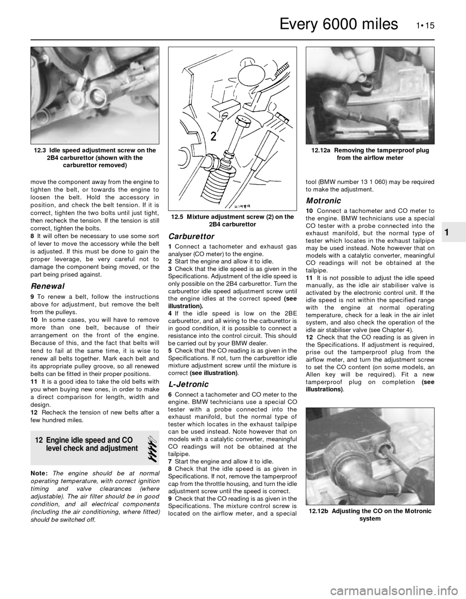
the engine idles at the correct speed (see
illustration).
4If the idle speed is low on the 2BE
carburettor, and all wiring to the carburettor is
in good condition, it is possible to connect a
resistance into the control circuit. This should
be carried out by your BMW dealer.
5Check that the CO reading is as given in the
Specifications. If not, turn the carburettor idle
mixture adjustment screw until the mixture is
correct (see illustration).
L-Jetronic
6Connect a tachometer and CO meter to the
engine. BMW technicians use a special CO
tester with a probe connected into the
exhaust manifold, but the normal type of
tester which locates in the exhaust tailpipe
can be used instead. Note however that on
models with a catalytic converter, meaningful
CO readings will not be obtained at the
tailpipe.
7Start the engine and allow it to idle.
8Check that the idle speed is as given in
Specifications. If not, remove the tamperproof
cap from the throttle housing, and turn the idle
adjustment screw until the speed is correct.
9Check that the CO reading is as given in the
Specifications. The mixture control screw is
located on the airflow meter, and a specialtool (BMW number 13 1 060) may be required
to make the adjustment.
Motronic
10Connect a tachometer and CO meter to
the engine. BMW technicians use a special
CO tester with a probe connected into the
exhaust manifold, but the normal type of
tester which locates in the exhaust tailpipe
may be used instead. Note however that on
models with a catalytic converter, meaningful
CO readings will not be obtained at the
tailpipe.
11It is not possible to adjust the idle speed
manually, as the idle air stabiliser valve is
activated by the electronic control unit. If the
idle speed is not within the specified range
with the engine at normal operating
temperature, check for a leak in the air inlet
system, and also check the operation of the
idle air stabiliser valve (see Chapter 4).
12Check that the CO reading is as given in
the Specifications. If adjustment is required,
prise out the tamperproof plug from the
airflow meter, and turn the adjustment screw
to set the CO content (on some models, an
Allen key will be required). Fit a new
tamperproof plug on completion (see
illustrations).
1•15
12.12a Removing the tamperproof plug
from the airflow meter
12.5 Mixture adjustment screw (2) on the
2B4 carburettor
12.3 Idle speed adjustment screw on the
2B4 carburettor (shown with the
carburettor removed)
12.12b Adjusting the CO on the Motronic
system
1
Every 6000 miles
Page 28 of 228
5With the engine cool, remove the HT lead
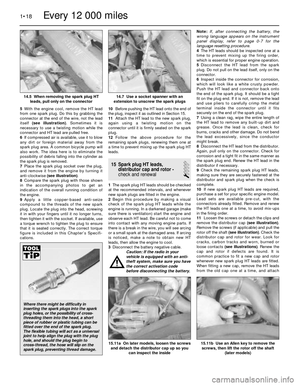
from one spark plug. Do this by grabbing the
connector at the end of the wire, not the lead
itself (see illustration). Sometimes it is
necessary to use a twisting motion while the
connector and HT lead are pulled free.
6If compressed air is available, use it to blow
any dirt or foreign material away from the
spark plug area. A common bicycle pump will
also work. The idea here is to eliminate the
possibility of debris falling into the cylinder as
the spark plug is removed.
7Place the spark plug socket over the plug,
and remove it from the engine by turning it
anti-clockwise (see illustration).
8Compare the spark plug with those shown
in the accompanying photos to get an
indication of the overall running condition of
the engine.
9Apply a little copper-based anti-seize
compound to the threads of the new spark
plug. Locate the plug into the head, screwing
it in with your fingers until it no longer turns,
then tighten it with the socket. If available, use
a torque wrench to tighten the plug to ensure
that it is seated correctly. The correct torque
figure is included in this Chapter’s Specifi-
cations.10Before pushing the HT lead onto the end of
the plug, inspect it as outlined in Section 15.
11Attach the HT lead to the new spark plug,
again using a twisting motion on the
connector until it is firmly seated on the spark
plug.
12Follow the above procedure for the
remaining spark plugs, renewing them one at
a time to prevent mixing up the spark plug HT
leads.
15 Spark plug HT leads,
distributor cap and rotor -
check and renewal
1
1The spark plug HT leads should be checked
at the recommended intervals, and whenever
new spark plugs are fitted in the engine.
2Begin this procedure by making a visual
check of the spark plug HT leads while the
engine is running. In a darkened garage (make
sure there is ventilation) start the engine and
observe each HT lead. Be careful not to come
into contact with any moving engine parts. If
there is a break in the wire, you will see arcing
or a small spark at the damaged area. If arcing
is noticed, make a note to obtain new HT
leads, then allow the engine to cool.
3Disconnect the battery negative cable.
Caution: If the radio in your
vehicle is equipped with an anti-
theft system, make sure you have
the correct activation code
before disconnecting the battery. Note: If, after connecting the battery, the
wrong language appears on the instrument
panel display, refer to page 0-7 for the
language resetting procedure.
4The HT leads should be inspected one at a
time to prevent mixing up the firing order,
which is essential for proper engine operation.
5Disconnect the HT lead from the spark
plug. Do not pull on the lead itself, only on the
connector.
6Inspect inside the connector for corrosion,
which will look like a white crusty powder.
Push the HT lead and connector back onto
the end of the spark plug. It should be a tight
fit on the plug end. If it is not, remove the lead
and use pliers to carefully crimp the metal
terminal inside the connector until it fits
securely on the end of the spark plug.
7Using a clean rag, wipe the entire length of
the HT lead to remove any built-up dirt and
grease. Once the lead is clean, check for
burns, cracks and other damage. Do not bend
the lead excessively, since the conductor
might break.
8Disconnect the HT lead from the distributor.
Again, pull only on the connector. Check for
corrosion and a tight fit in the same manner as
the spark plug end. Renew the HT lead in the
distributor if necessary.
9Check the remaining spark plug HT leads,
making sure they are securely fastened at the
distributor and spark plug when the check is
complete.
10If new spark plug HT leads are required,
purchase a set for your specific engine model.
Lead sets are available pre-cut, with the
connectors already fitted. Remove and renew
the HT leads one at a time, to avoid mix-ups
in the firing order.
11Loosen the screws or detach the clips and
remove the distributor cap (see illustration).
Remove the screws (if applicable) and pull the
rotor off the shaft (see illustration). Check the
distributor cap and rotor for wear. Look for
cracks, carbon tracks and worn, burned or
loose contacts (see illustrations). Renew the
cap and rotor if defects are found. It is
common practice to fit a new cap and rotor
whenever new spark plug HT leads are fitted.
When fitting a new cap, remove the HT leads
from the old cap one at a time, and attach
1•18
15.11b Use an Allen key to remove the
screws, then lift the rotor off the shaft
(later models)15.11a On later models, loosen the screws
and detach the distributor cap up so you
can inspect the inside
14.7 Use a socket spanner with an
extension to unscrew the spark plugs14.5 When removing the spark plug HT
leads, pull only on the connector
Every 12 000 miles
Where there might be difficulty in
inserting the spark plugs into the spark
plug holes, or the possibility of cross-
threading them into the head, a short
piece of rubber or plastic tubing can be
fitted over the end of the spark plug.
The flexible tubing will act as a universal
joint to help align the plug with the plug
hole, and should the plug begin to
cross-thread, the hose will slip on the
spark plug, preventing thread damage.
Page 29 of 228
them to the new cap in the exact same
location - do not simultaneously remove all
the HT leads, or firing order mix-ups may
occur.
16 Manual transmission
lubricant level check
1
1The transmission has a filler/level plug
which must be removed to check the lubricant
level. If the vehicle is raised to gain access to
the plug, be sure to support it safely - do not
crawl under a vehicle which is supported only
by a jack!Note:The vehicle should be level to
give an accurate lubricant check.
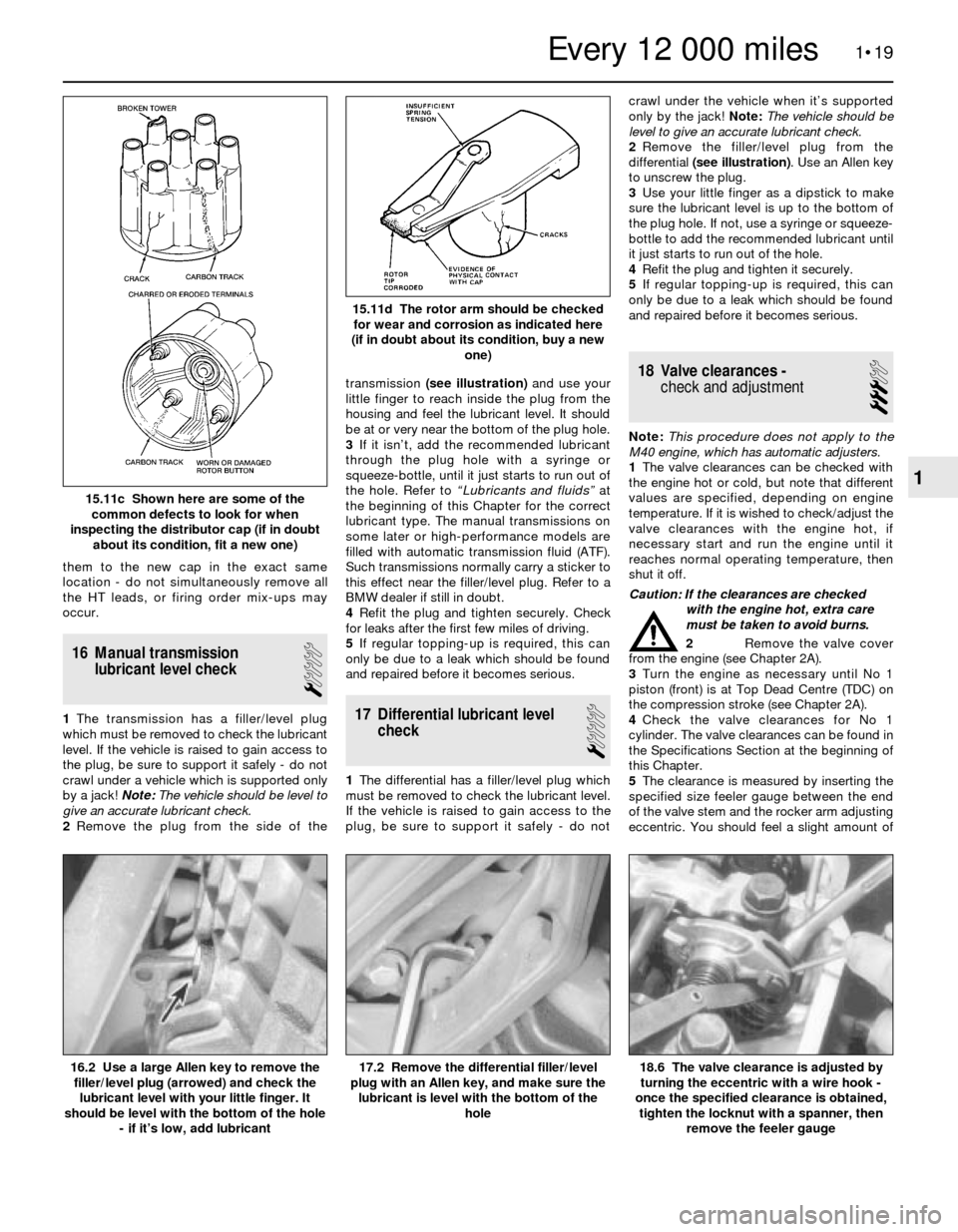
2Remove the plug from the side of thetransmission (see illustration)and use your
little finger to reach inside the plug from the
housing and feel the lubricant level. It should
be at or very near the bottom of the plug hole.
3If it isn’t, add the recommended lubricant
through the plug hole with a syringe or
squeeze-bottle, until it just starts to run out of
the hole. Refer to “Lubricants and fluids” at
the beginning of this Chapter for the correct
lubricant type. The manual transmissions on
some later or high-performance models are
filled with automatic transmission fluid (ATF).
Such transmissions normally carry a sticker to
this effect near the filler/level plug. Refer to a
BMW dealer if still in doubt.
4Refit the plug and tighten securely. Check
for leaks after the first few miles of driving.
5If regular topping-up is required, this can
only be due to a leak which should be found
and repaired before it becomes serious.17 Differential lubricant level
check
1
1The differential has a filler/level plug which
must be removed to check the lubricant level.
If the vehicle is raised to gain access to the
plug, be sure to support it safely - do notcrawl under the vehicle when it’s supported
only by the jack! Note:The vehicle should be
level to give an accurate lubricant check.
2Remove the filler/level plug from the
differential (see illustration). Use an Allen key
to unscrew the plug.
3Use your little finger as a dipstick to make
sure the lubricant level is up to the bottom of
the plug hole. If not, use a syringe or squeeze-
bottle to add the recommended lubricant until
it just starts to run out of the hole.
4Refit the plug and tighten it securely.
5If regular topping-up is required, this can
only be due to a leak which should be found
and repaired before it becomes serious.
18 Valve clearances -
check and adjustment
3
Note:This procedure does not apply to the
M40 engine, which has automatic adjusters.
1The valve clearances can be checked with
the engine hot or cold, but note that different
values are specified, depending on engine
temperature. If it is wished to check/adjust the
valve clearances with the engine hot, if
necessary start and run the engine until it
reaches normal operating temperature, then
shut it off.
Caution: If the clearances are checked
with the engine hot, extra care
must be taken to avoid burns.
2Remove the valve cover
from the engine (see Chapter 2A).
3Turn the engine as necessary until No 1
piston (front) is at Top Dead Centre (TDC) on
the compression stroke (see Chapter 2A).
4Check the valve clearances for No 1
cylinder. The valve clearances can be found in
the Specifications Section at the beginning of
this Chapter.
5The clearance is measured by inserting the
specified size feeler gauge between the end
of the valve stem and the rocker arm adjusting
eccentric. You should feel a slight amount of
1•19
15.11d The rotor arm should be checked
for wear and corrosion as indicated here
(if in doubt about its condition, buy a new
one)
15.11c Shown here are some of the
common defects to look for when
inspecting the distributor cap (if in doubt
about its condition, fit a new one)
18.6 The valve clearance is adjusted by
turning the eccentric with a wire hook -
once the specified clearance is obtained,
tighten the locknut with a spanner, then
remove the feeler gauge17.2 Remove the differential filler/level
plug with an Allen key, and make sure the
lubricant is level with the bottom of the
hole16.2 Use a large Allen key to remove the
filler/level plug (arrowed) and check the
lubricant level with your little finger. It
should be level with the bottom of the hole
- if it’s low, add lubricant
1
Every 12 000 miles
Page 34 of 228
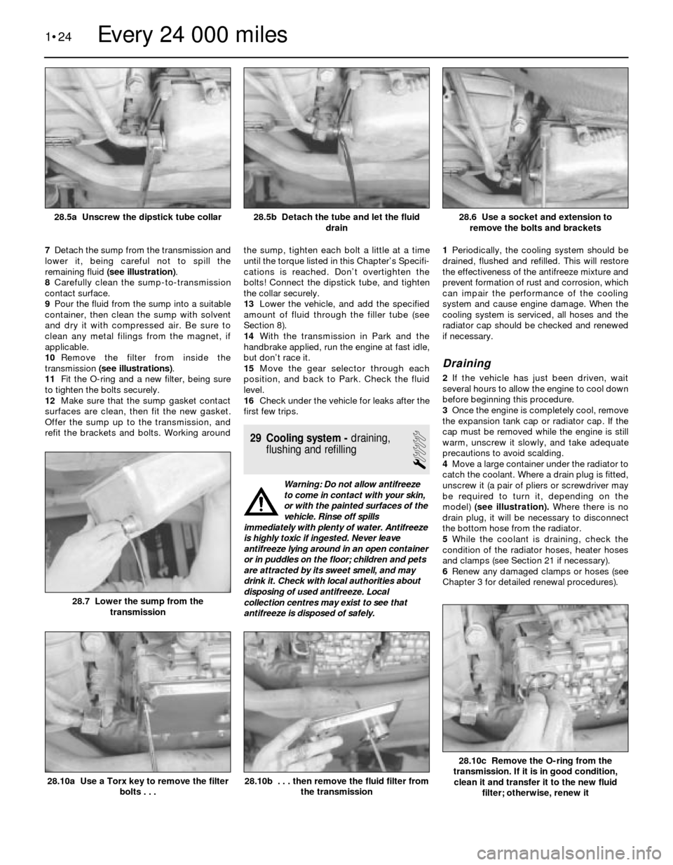
7Detach the sump from the transmission and
lower it, being careful not to spill the
remaining fluid (see illustration).
8Carefully clean the sump-to-transmission
contact surface.
9Pour the fluid from the sump into a suitable
container, then clean the sump with solvent
and dry it with compressed air. Be sure to
clean any metal filings from the magnet, if
applicable.
10Remove the filter from inside the
transmission (see illustrations).
11Fit the O-ring and a new filter, being sure
to tighten the bolts securely.
12Make sure that the sump gasket contact
surfaces are clean, then fit the new gasket.
Offer the sump up to the transmission, and
refit the brackets and bolts. Working aroundthe sump, tighten each bolt a little at a time
until the torque listed in this Chapter’s Specifi-
cations is reached. Don’t overtighten the
bolts! Connect the dipstick tube, and tighten
the collar securely.
13Lower the vehicle, and add the specified
amount of fluid through the filler tube (see
Section 8).
14With the transmission in Park and the
handbrake applied, run the engine at fast idle,
but don’t race it.
15Move the gear selector through each
position, and back to Park. Check the fluid
level.
16Check under the vehicle for leaks after the
first few trips.
29 Cooling system -draining,
flushing and refilling
1
Warning: Do not allow antifreeze
to come in contact with your skin,
or with the painted surfaces of the
vehicle. Rinse off spills
immediately with plenty of water. Antifreeze
is highly toxic if ingested. Never leave
antifreeze lying around in an open container
or in puddles on the floor; children and pets
are attracted by its sweet smell, and may
drink it. Check with local authorities about
disposing of used antifreeze. Local
collection centres may exist to see that
antifreeze is disposed of safely.1Periodically, the cooling system should be
drained, flushed and refilled. This will restore
the effectiveness of the antifreeze mixture and
prevent formation of rust and corrosion, which
can impair the performance of the cooling
system and cause engine damage. When the
cooling system is serviced, all hoses and the
radiator cap should be checked and renewed
if necessary.
Draining
2If the vehicle has just been driven, wait
several hours to allow the engine to cool down
before beginning this procedure.
3Once the engine is completely cool, remove
the expansion tank cap or radiator cap. If the
cap must be removed while the engine is still
warm, unscrew it slowly, and take adequate
precautions to avoid scalding.
4Move a large container under the radiator to
catch the coolant. Where a drain plug is fitted,
unscrew it (a pair of pliers or screwdriver may
be required to turn it, depending on the
model) (see illustration). Where there is no
drain plug, it will be necessary to disconnect
the bottom hose from the radiator.
5While the coolant is draining, check the
condition of the radiator hoses, heater hoses
and clamps (see Section 21 if necessary).
6Renew any damaged clamps or hoses (see
Chapter 3 for detailed renewal procedures).
1•24
28.10c Remove the O-ring from the
transmission. If it is in good condition,
clean it and transfer it to the new fluid
filter; otherwise, renew it
28.10b . . . then remove the fluid filter from
the transmission28.10a Use a Torx key to remove the filter
bolts . . .
28.7 Lower the sump from the
transmission
28.6 Use a socket and extension to
remove the bolts and brackets28.5b Detach the tube and let the fluid
drain28.5a Unscrew the dipstick tube collar
Every 24 000 miles
Page 35 of 228
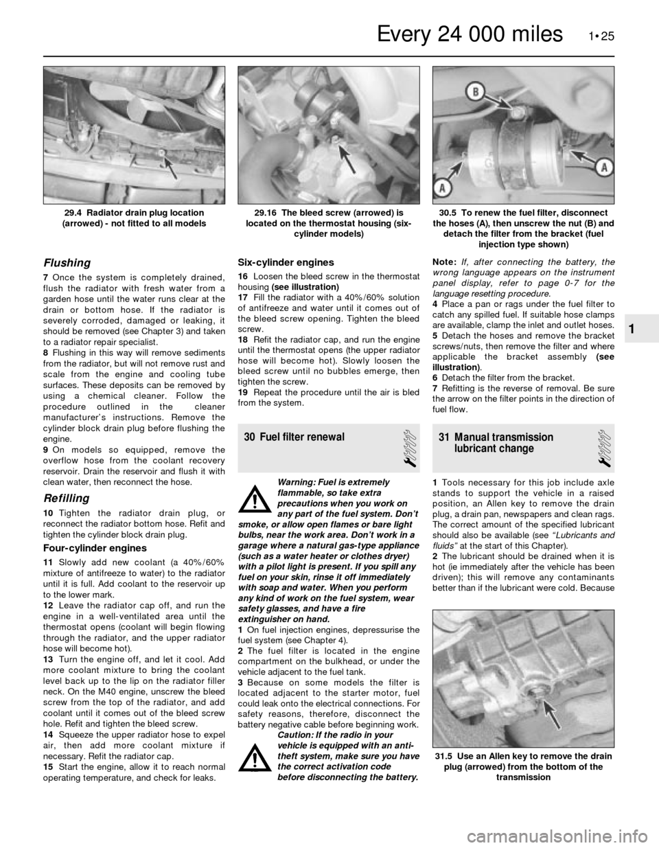
Flushing
7Once the system is completely drained,
flush the radiator with fresh water from a
garden hose until the water runs clear at the
drain or bottom hose. If the radiator is
severely corroded, damaged or leaking, it
should be removed (see Chapter 3) and taken
to a radiator repair specialist.
8Flushing in this way will remove sediments
from the radiator, but will not remove rust and
scale from the engine and cooling tube
surfaces. These deposits can be removed by
using a chemical cleaner. Follow the
procedure outlined in the cleaner
manufacturer’s instructions. Remove the
cylinder block drain plug before flushing the
engine.
9On models so equipped, remove the
overflow hose from the coolant recovery
reservoir. Drain the reservoir and flush it with
clean water, then reconnect the hose.
Refilling
10Tighten the radiator drain plug, or
reconnect the radiator bottom hose. Refit and
tighten the cylinder block drain plug.
Four-cylinder engines
11Slowly add new coolant (a 40%/60%
mixture of antifreeze to water) to the radiator
until it is full. Add coolant to the reservoir up
to the lower mark.
12Leave the radiator cap off, and run the
engine in a well-ventilated area until the
thermostat opens (coolant will begin flowing
through the radiator, and the upper radiator
hose will become hot).
13Turn the engine off, and let it cool. Add
more coolant mixture to bring the coolant
level back up to the lip on the radiator filler
neck. On the M40 engine, unscrew the bleed
screw from the top of the radiator, and add
coolant until it comes out of the bleed screw
hole. Refit and tighten the bleed screw.
14Squeeze the upper radiator hose to expel
air, then add more coolant mixture if
necessary. Refit the radiator cap.
15Start the engine, allow it to reach normal
operating temperature, and check for leaks.
Six-cylinder engines
16Loosen the bleed screw in the thermostat
housing (see illustration)
17Fill the radiator with a 40%/60% solution
of antifreeze and water until it comes out of
the bleed screw opening. Tighten the bleed
screw.
18Refit the radiator cap, and run the engine
until the thermostat opens (the upper radiator
hose will become hot). Slowly loosen the
bleed screw until no bubbles emerge, then
tighten the screw.
19Repeat the procedure until the air is bled
from the system.
30 Fuel filter renewal
1
Warning: Fuel is extremely
flammable, so take extra
precautions when you work on
any part of the fuel system. Don’t
smoke, or allow open flames or bare light
bulbs, near the work area. Don’t work in a
garage where a natural gas-type appliance
(such as a water heater or clothes dryer)
with a pilot light is present. If you spill any
fuel on your skin, rinse it off immediately
with soap and water. When you perform
any kind of work on the fuel system, wear
safety glasses, and have a fire
extinguisher on hand.
1On fuel injection engines, depressurise the
fuel system (see Chapter 4).
2The fuel filter is located in the engine
compartment on the bulkhead, or under the
vehicle adjacent to the fuel tank.
3Because on some models the filter is
located adjacent to the starter motor, fuel
could leak onto the electrical connections. For
safety reasons, therefore, disconnect the
battery negative cable before beginning work.
Caution: If the radio in your
vehicle is equipped with an anti-
theft system, make sure you have
the correct activation code
before disconnecting the battery.Note: If, after connecting the battery, the
wrong language appears on the instrument
panel display, refer to page 0-7 for the
language resetting procedure.
4Place a pan or rags under the fuel filter to
catch any spilled fuel. If suitable hose clamps
are available, clamp the inlet and outlet hoses.
5 Detach the hoses and remove the bracket
screws/nuts, then remove the filter and where
applicable the bracket assembly (see
illustration).
6Detach the filter from the bracket.
7Refitting is the reverse of removal. Be sure
the arrow on the filter points in the direction of
fuel flow.
31 Manual transmission
lubricant change
1
1Tools necessary for this job include axle
stands to support the vehicle in a raised
position, an Allen key to remove the drain
plug, a drain pan, newspapers and clean rags.
The correct amount of the specified lubricant
should also be available (see “Lubricants and
fluids”at the start of this Chapter).
2The lubricant should be drained when it is
hot (ie immediately after the vehicle has been
driven); this will remove any contaminants
better than if the lubricant were cold. Because
1•25
30.5 To renew the fuel filter, disconnect
the hoses (A), then unscrew the nut (B) and
detach the filter from the bracket (fuel
injection type shown)29.16 The bleed screw (arrowed) is
located on the thermostat housing (six-
cylinder models)29.4 Radiator drain plug location
(arrowed) - not fitted to all models
31.5 Use an Allen key to remove the drain
plug (arrowed) from the bottom of the
transmission
1
Every 24 000 miles
Page 36 of 228
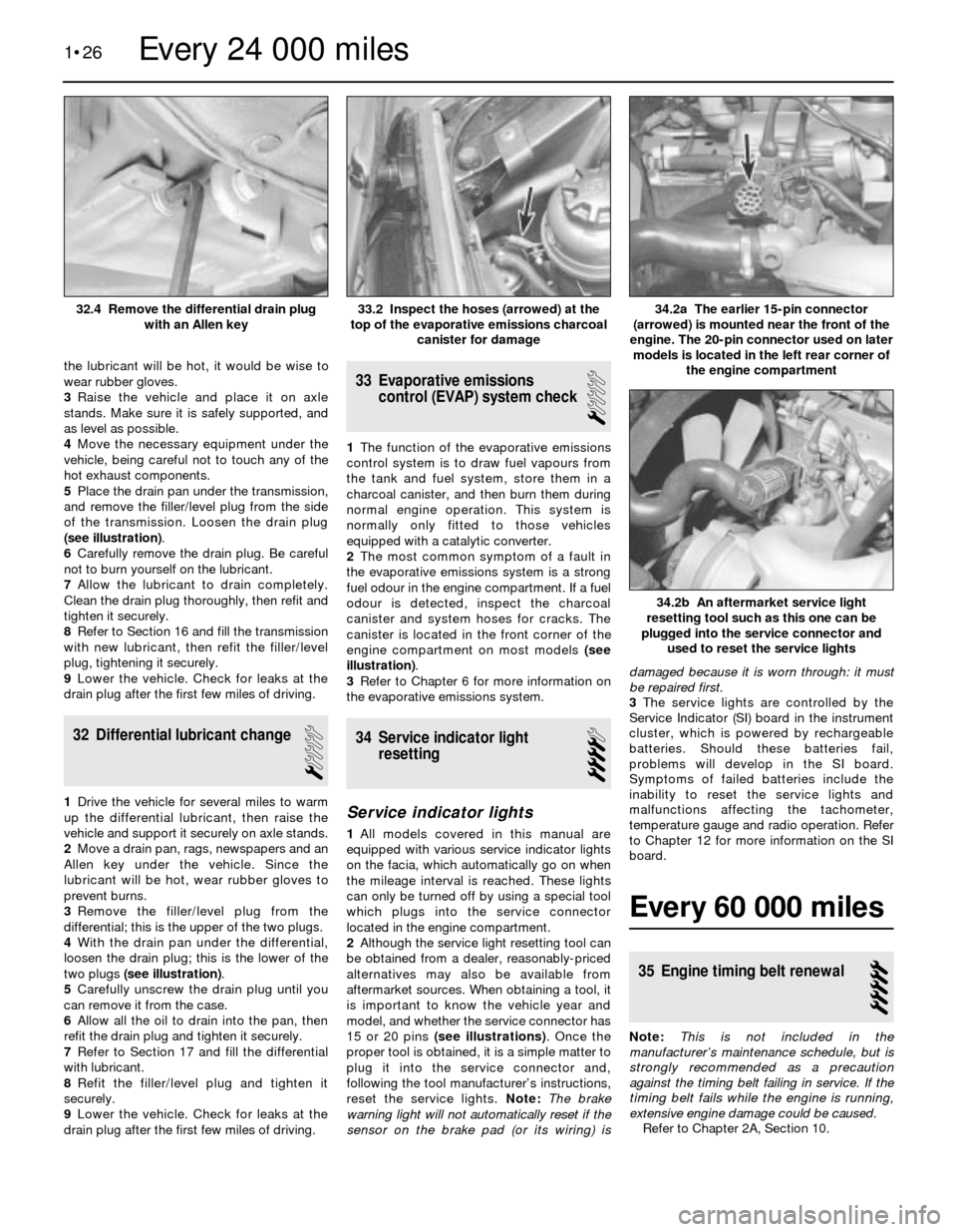
the lubricant will be hot, it would be wise to
wear rubber gloves.
3Raise the vehicle and place it on axle
stands. Make sure it is safely supported, and
as level as possible.
4Move the necessary equipment under the
vehicle, being careful not to touch any of the
hot exhaust components.
5Place the drain pan under the transmission,
and remove the filler/level plug from the side
of the transmission. Loosen the drain plug
(see illustration).
6Carefully remove the drain plug. Be careful
not to burn yourself on the lubricant.
7Allow the lubricant to drain completely.
Clean the drain plug thoroughly, then refit and
tighten it securely.
8Refer to Section 16 and fill the transmission
with new lubricant, then refit the filler/level
plug, tightening it securely.
9Lower the vehicle. Check for leaks at the
drain plug after the first few miles of driving.
32 Differential lubricant change
1
1Drive the vehicle for several miles to warm
up the differential lubricant, then raise the
vehicle and support it securely on axle stands.
2Move a drain pan, rags, newspapers and an
Allen key under the vehicle. Since the
lubricant will be hot, wear rubber gloves to
prevent burns.
3Remove the filler/level plug from the
differential; this is the upper of the two plugs.
4With the drain pan under the differential,
loosen the drain plug; this is the lower of the
two plugs (see illustration).
5Carefully unscrew the drain plug until you
can remove it from the case.
6Allow all the oil to drain into the pan, then
refit the drain plug and tighten it securely.
7Refer to Section 17 and fill the differential
with lubricant.
8Refit the filler/level plug and tighten it
securely.
9Lower the vehicle. Check for leaks at the
drain plug after the first few miles of driving.
33 Evaporative emissions
control (EVAP) system check
1
1The function of the evaporative emissions
control system is to draw fuel vapours from
the tank and fuel system, store them in a
charcoal canister, and then burn them during
normal engine operation. This system is
normally only fitted to those vehicles
equipped with a catalytic converter.
2The most common symptom of a fault in
the evaporative emissions system is a strong
fuel odour in the engine compartment. If a fuel
odour is detected, inspect the charcoal
canister and system hoses for cracks. The
canister is located in the front corner of the
engine compartment on most models (see
illustration).
3Refer to Chapter 6 for more information on
the evaporative emissions system.
34 Service indicator light
resetting
4
Service indicator lights
1All models covered in this manual are
equipped with various service indicator lights
on the facia, which automatically go on when
the mileage interval is reached. These lights
can only be turned off by using a special tool
which plugs into the service connector
located in the engine compartment.
2Although the service light resetting tool can
be obtained from a dealer, reasonably-priced
alternatives may also be available from
aftermarket sources. When obtaining a tool, it
is important to know the vehicle year and
model, and whether the service connector has
15 or 20 pins (see illustrations). Once the
proper tool is obtained, it is a simple matter to
plug it into the service connector and,
following the tool manufacturer’s instructions,
reset the service lights. Note: The brake
warning light will not automatically reset if the
sensor on the brake pad (or its wiring) isdamaged because it is worn through: it must
be repaired first.
3The service lights are controlled by the
Service Indicator (SI) board in the instrument
cluster, which is powered by rechargeable
batteries. Should these batteries fail,
problems will develop in the SI board.
Symptoms of failed batteries include the
inability to reset the service lights and
malfunctions affecting the tachometer,
temperature gauge and radio operation. Refer
to Chapter 12 for more information on the SI
board.
Every 60 000 miles
35 Engine timing belt renewal
5
Note:This is not included in the
manufacturer’s maintenance schedule, but is
strongly recommended as a precaution
against the timing belt failing in service. If the
timing belt fails while the engine is running,
extensive engine damage could be caused.
Refer to Chapter 2A, Section 10.
1•26
34.2b An aftermarket service light
resetting tool such as this one can be
plugged into the service connector and
used to reset the service lights
34.2a The earlier 15-pin connector
(arrowed) is mounted near the front of the
engine. The 20-pin connector used on later
models is located in the left rear corner of
the engine compartment33.2 Inspect the hoses (arrowed) at the
top of the evaporative emissions charcoal
canister for damage32.4 Remove the differential drain plug
with an Allen key
Every 24 000 miles
Page 44 of 228
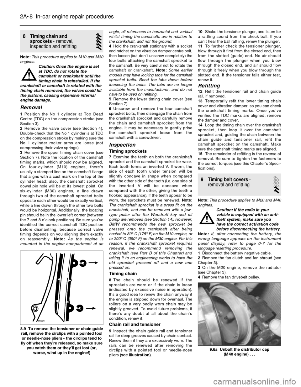
8 Timing chain and
sprockets- removal,
inspection and refitting
5
Note:This procedure applies to M10 and M30
engines.
Caution: Once the engine is set
at TDC, do not rotate the
camshaft or crankshaft until the
timing chain is reinstalled. If the
crankshaft or camshaft is rotated with the
timing chain removed, the valves could hit
the pistons, causing expensive internal
engine damage.
Removal
1Position the No 1 cylinder at Top Dead
Centre (TDC) on the compression stroke (see
Section 3).
2Remove the valve cover (see Section 4).
Double-check that the No 1 cylinder is at TDC
on the compression stroke by making sure the
No 1 cylinder rocker arms are loose (not
compressing their valve springs).
3Remove the upper timing chain cover (see
Section 7). Note the location of the camshaft
timing marks, which should now be aligned.
On four-cylinder (M10) engines, there’s
usually a stamped line on the camshaft flange
that aligns with a cast mark on the top of the
cylinder head; also, the camshaft sprocket
dowel pin hole will be at its lowest point. On
six-cylinder (M30) engines, a line drawn
through two of the camshaft sprocket bolts
opposite each other would be exactly vertical,
while a line drawn through the other two bolts
would be horizontal. Additionally, the locating
pin should be in the lower left corner (between
the 7 and 8 o’clock positions). Be sure you’ve
identified the correct camshaft TDC position
before dismantling, because correct valve
timing depends on you aligning them exactly
on reassembly. Note:As the engine is
mounted in the engine compartment at anangle, all references to horizontal and vertical
whilst timing the camshafts are in relation to
the crankshaft, and not the ground.
4Hold the crankshaft stationary with a socket
and ratchet on the vibration damper centre bolt,
then loosen (but don’t unscrew completely) the
four bolts attaching the camshaft sprocket to
the camshaft. Be very careful not to rotate the
camshaft or crankshaft. Note:Some earlier
models may have locking tabs for the camshaft
sprocket bolts. Bend the tabs down before
loosening the bolts. The tabs are no longer
available from the manufacturer, and do not
have to be used on refitting.
5Remove the lower timing chain cover (see
Section 7).
6Unscrew and remove the four camshaft
sprocket bolts, then disengage the chain from
the crankshaft sprocket and carefully remove
the chain and camshaft sprocket from the
engine. It may be necessary to gently prise
the camshaft sprocket loose from the
camshaft with a screwdriver.
Inspection
Timing sprockets
7Examine the teeth on both the crankshaft
sprocket and the camshaft sprocket for wear.
Each tooth forms an inverted V. If worn, the
side of each tooth under tension will be
slightly concave in shape when compared
with the other side of the tooth (i.e. one side of
the inverted V will be concave when
compared with the other, giving the teeth a
hooked appearance). If the teeth appear to be
worn, the sprockets must be renewed. Note:
The crankshaft sprocket is a press fit on the
crankshaft, and can be removed with a jaw-
type puller after the Woodruff key and oil
pump are removed (see Section 14). However,
BMW recommends the new sprocket be
pressed onto the crankshaft after being
heated to 80°C (175°F) on the M10 engine, or
to 200°C(390°F) on the M30 engine. For this
reason, if the crankshaft sprocket requires
renewal, we recommend removing the
crankshaft (see Part B of this Chapter) and
taking it to an engineering works to have the
old sprocket pressed off and a new one
pressed on.
Timing chain
8The chain should be renewed if the
sprockets are worn or if the chain is loose
(indicated by excessive noise in operation).
It’s a good idea to renew the chain anyway if
the engine is stripped down for overhaul. The
rollers on a very badly worn chain may be
slightly grooved. To avoid future problems, if
there’s any doubt at all about the chain’s
condition, renew it.
Chain rail and tensioner
9Inspect the chain guide rail and tensioner
rail for deep grooves caused by chain contact.
Renew them if they are excessively worn. The
rails can be renewed after removing the
circlips with a pointed tool or needle-nose
pliers (see illustration).10Shake the tensioner plunger, and listen for
a rattling sound from the check ball. If you
can’t hear the ball rattling, renew the plunger.
11To further check the tensioner plunger,
blow through it first from the closed end, then
from the slotted (guide) end. No air should
flow through the plunger when you blow
through the closed end, and air should flow
through it freely when you blow through the
slotted end. If the tensioner fails either test,
renew it.
Refitting
12Refit the tensioner rail and chain guide
rail, if removed.
13Temporarily refit the lower timing chain
cover and vibration damper, so you can check
the crankshaft timing marks. Once you’ve
verified the TDC marks are aligned, remove
the damper and cover.
14Loop the timing chain over the crankshaft
sprocket, then loop it over the camshaft
sprocket and, guiding the chain between the
chain guide and tensioner rail, refit the
camshaft sprocket on the camshaft. Make
sure the camshaft timing marks are aligned.
15The remainder of refitting is the reverse of
removal. Be sure to tighten the fasteners to
the correct torques (see this Chapter’s Speci-
fications).
9 Timing belt covers-
removal and refitting
2
Note:This procedure applies to M20 and M40
engines.
Caution: If the radio in your
vehicle is equipped with an anti-
theft system, make sure you
have the correct activation code
before disconnecting the battery.
Note: If, after connecting the battery, the
wrong language appears on the instrument
panel display, refer to page 0-7 for the
language resetting procedure.
1Disconnect the battery negative cable.
2Remove the fan clutch and fan shroud (see
Chapter 3).
3On the M20 engine, remove the radiator
(see Chapter 3).
4Remove the fan drivebelt pulley.
2A•8 In-car engine repair procedures
9.6a Unbolt the distributor cap
(M40 engine) . . .
8.9 To remove the tensioner or chain guide
rail, remove the circlips with a pointed tool
or needle-nose pliers - the circlips tend to
fly off when they’re released, so make sure
you catch them or they’ll get lost (or,
worse, wind up in the engine!)
Page 46 of 228
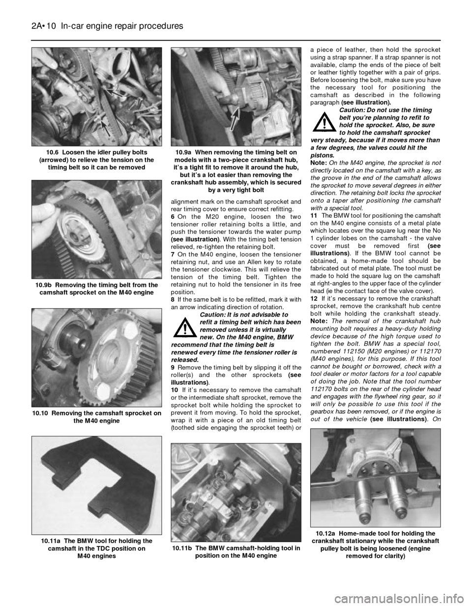
alignment mark on the camshaft sprocket and
rear timing cover to ensure correct refitting.
6On the M20 engine, loosen the two
tensioner roller retaining bolts a little, and
push the tensioner towards the water pump
(see illustration). With the timing belt tension
relieved, re-tighten the retaining bolt.
7On the M40 engine, loosen the tensioner
retaining nut, and use an Allen key to rotate
the tensioner clockwise. This will relieve the
tension of the timing belt. Tighten the
retaining nut to hold the tensioner in its free
position.
8If the same belt is to be refitted, mark it with
an arrow indicating direction of rotation.
Caution: It is not advisable to
refit a timing belt which has been
removed unless it is virtually
new. On the M40 engine, BMW
recommend that the timing belt is
renewed every time the tensioner roller is
released.
9Remove the timing belt by slipping it off the
roller(s) and the other sprockets (see
illustrations).
10If it’s necessary to remove the camshaft
or the intermediate shaft sprocket, remove the
sprocket bolt while holding the sprocket to
prevent it from moving. To hold the sprocket,
wrap it with a piece of an old timing belt
(toothed side engaging the sprocket teeth) ora piece of leather, then hold the sprocket
using a strap spanner. If a strap spanner is not
available, clamp the ends of the piece of belt
or leather tightly together with a pair of grips.
Before loosening the bolt, make sure you have
the necessary tool for positioning the
camshaft as described in the following
paragraph (see illustration).
Caution: Do not use the timing
belt you’re planning to refit to
hold the sprocket. Also, be sure
to hold the camshaft sprocket
very steady, because if it moves more than
a few degrees, the valves could hit the
pistons.
Note: On the M40 engine, the sprocket is not
directly located on the camshaft with a key, as
the groove in the end of the camshaft allows
the sprocket to move several degrees in either
direction. The retaining bolt locks the sprocket
onto a taper after positioning the camshaft
with a special tool.
11The BMW tool for positioning the camshaft
on the M40 engine consists of a metal plate
which locates over the square lug near the No
1 cylinder lobes on the camshaft - the valve
cover must be removed first (see
illustrations). If the BMW tool cannot be
obtained, a home-made tool should be
fabricated out of metal plate. The tool must be
made to hold the square lug on the camshaft
at right-angles to the upper face of the cylinder
head (ie the contact face of the valve cover).
12If it’s necessary to remove the crankshaft
sprocket, remove the crankshaft hub centre
bolt while holding the crankshaft steady.
Note:The removal of the crankshaft hub
mounting bolt requires a heavy-duty holding
device because of the high torque used to
tighten the bolt. BMW has a special tool,
numbered 112150 (M20 engines) or 112170
(M40 engines), for this purpose. If this tool
cannot be bought or borrowed, check with a
tool dealer or motor factors for a tool capable
of doing the job. Note that the tool number
112170 bolts on the rear of the cylinder head
and engages with the flywheel ring gear, so it
will only be possible to use this tool if the
gearbox has been removed, or if the engine is
out of the vehicle (see illustrations). On
2A•10 In-car engine repair procedures
10.12a Home-made tool for holding the
crankshaft stationary while the crankshaft
pulley bolt is being loosened (engine
removed for clarity)
10.11b The BMW camshaft-holding tool in
position on the M40 engine10.11a The BMW tool for holding the
camshaft in the TDC position on
M40 engines
10.10 Removing the camshaft sprocket on
the M40 engine
10.9b Removing the timing belt from the
camshaft sprocket on the M40 engine
10.9a When removing the timing belt on
models with a two-piece crankshaft hub,
it’s a tight fit to remove it around the hub,
but it’s a lot easier than removing the
crankshaft hub assembly, which is secured
by a very tight bolt10.6 Loosen the idler pulley bolts
(arrowed) to relieve the tension on the
timing belt so it can be removed
Page 47 of 228
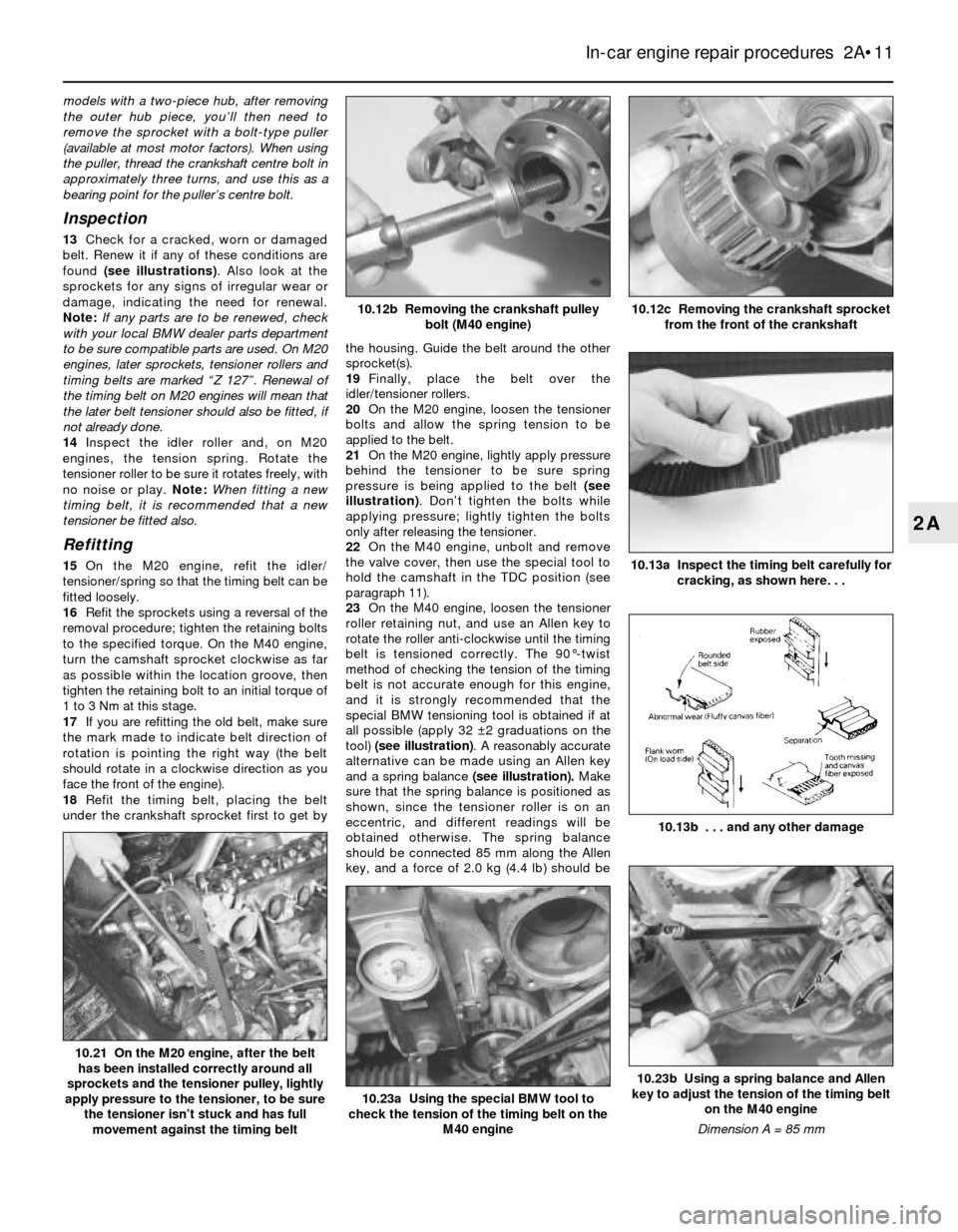
models with a two-piece hub, after removing
the outer hub piece, you’ll then need to
remove the sprocket with a bolt-type puller
(available at most motor factors). When using
the puller, thread the crankshaft centre bolt in
approximately three turns, and use this as a
bearing point for the puller’s centre bolt.
Inspection
13Check for a cracked, worn or damaged
belt. Renew it if any of these conditions are
found (see illustrations). Also look at the
sprockets for any signs of irregular wear or
damage, indicating the need for renewal.
Note:If any parts are to be renewed, check
with your local BMW dealer parts department
to be sure compatible parts are used. On M20
engines, later sprockets, tensioner rollers and
timing belts are marked “Z 127”. Renewal of
the timing belt on M20 engines will mean that
the later belt tensioner should also be fitted, if
not already done.
14Inspect the idler roller and, on M20
engines, the tension spring. Rotate the
tensioner roller to be sure it rotates freely, with
no noise or play. Note:When fitting a new
timing belt, it is recommended that a new
tensioner be fitted also.
Refitting
15On the M20 engine, refit the idler/
tensioner/spring so that the timing belt can be
fitted loosely.
16Refit the sprockets using a reversal of the
removal procedure; tighten the retaining bolts
to the specified torque. On the M40 engine,
turn the camshaft sprocket clockwise as far
as possible within the location groove, then
tighten the retaining bolt to an initial torque of
1 to 3 Nm at this stage.
17If you are refitting the old belt, make sure
the mark made to indicate belt direction of
rotation is pointing the right way (the belt
should rotate in a clockwise direction as you
face the front of the engine).
18Refit the timing belt, placing the belt
under the crankshaft sprocket first to get bythe housing. Guide the belt around the other
sprocket(s).
19Finally, place the belt over the
idler/tensioner rollers.
20On the M20 engine, loosen the tensioner
bolts and allow the spring tension to be
applied to the belt.
21On the M20 engine, lightly apply pressure
behind the tensioner to be sure spring
pressure is being applied to the belt (see
illustration). Don’t tighten the bolts while
applying pressure; lightly tighten the bolts
only after releasing the tensioner.
22On the M40 engine, unbolt and remove
the valve cover, then use the special tool to
hold the camshaft in the TDC position (see
paragraph 11).
23On the M40 engine, loosen the tensioner
roller retaining nut, and use an Allen key to
rotate the roller anti-clockwise until the timing
belt is tensioned correctly. The 90°-twist
method of checking the tension of the timing
belt is not accurate enough for this engine,
and it is strongly recommended that the
special BMW tensioning tool is obtained if at
all possible (apply 32 ±2 graduations on the
tool) (see illustration). A reasonably accurate
alternative can be made using an Allen key
and a spring balance (see illustration).Make
sure that the spring balance is positioned as
shown, since the tensioner roller is on an
eccentric, and different readings will be
obtained otherwise. The spring balance
should be connected 85 mm along the Allen
key, and a force of 2.0 kg (4.4 lb) should be
In-car engine repair procedures 2A•11
10.13a Inspect the timing belt carefully for
cracking, as shown here. . .
10.13b . . . and any other damage
10.12c Removing the crankshaft sprocket
from the front of the crankshaft10.12b Removing the crankshaft pulley
bolt (M40 engine)
10.23b Using a spring balance and Allen
key to adjust the tension of the timing belt
on the M40 engine
Dimension A = 85 mm
10.23a Using the special BMW tool to
check the tension of the timing belt on the
M40 engine
10.21 On the M20 engine, after the belt
has been installed correctly around all
sprockets and the tensioner pulley, lightly
apply pressure to the tensioner, to be sure
the tensioner isn’t stuck and has full
movement against the timing belt
2A
Page 49 of 228
22Using a scraper, remove all traces of old
gasket material from the sealing surfaces of
the covers and engine block.
Caution: Be very careful not to
scratch or gouge the delicate
aluminium surfaces. Also, do not
damage the sump gasket, and
keep it clean. Gasket removal solvents are
available at motor factors, and may
prove helpful. After all gasket material has
been removed, the gasket surfaces
can be degreased by wiping them
with a rag dampened with a suitable
solvent.
23Support the cover on two blocks of wood,
and drive out the seals from behind with a
hammer and screwdriver. Be very careful not
to damage the seal bores in the process.
24Coat the outside diameters and lips of the
new seals with multi-purpose grease, and
drive the seals into the cover with a hammer
and a socket slightly smaller in diameter than
the outside diameter of the seal.
25Apply a film of RTV-type gasket sealant to
the surface of the sump gasket that mates
with the front cover. Apply extra beads of RTV
sealant to the edges where the gasket meets
the engine block. Note:If the sump gasket is
damaged, instead of fitting a whole new
gasket, you might try trimming the front
portion of the gasket off at the point where it
meets the engine block, then trim off the front
portion of a new sump gasket so it’s exactly
the same size. Cover the exposed inside area
of the sump with a rag, then clean all traces of
old gasket material off the area where the
gasket was removed. Attach the new gasket
piece to the sump with contact-cement-type
gasket adhesive, then apply RTV-type sealant
as described at the beginning of this
paragraph.
26Coat both sides of the new gasket with
RTV-type gasket sealant, then attach the front
cover to the front of the engine, carefully
working the seals over the crankshaft and
intermediate shaft. Refit the bolts and tighten
them evenly to the torque listed in this
Chapter’s Specifications. Work from bolt-to-
bolt in a criss-cross pattern, to be sure they’re
tightened evenly.Note 1:Tighten the front
cover-to-block bolts first, then tighten the
sump-to-cover bolts. Note 2:After applying
RTV-type sealant, reassembly must be
completed in about 10 minutes so the RTV
won’t prematurely harden.
27The remainder of refitting is the reverse of
removal.
Crankshaft front seal (M40 engines)
28Remove the timing belt and crankshaft
sprocket (see Section 10).
29Remove the Woodruff key from the
groove in the end of the crankshaft.
30Note the fitted position of the oil seal, then
prise it out from the front cover using a
screwdriver, but take care not to damage the
bore of the cover or the surface of thecrankshaft. If the seal is tight, drill two small
holes in the metal end of the seal, and use two
self-tapping screws to pull out the seal. Make
sure all remains of swarf are removed.
31Coat the outside diameter and lip of the
new seal with multi-purpose grease, then
drive it into the cover with a hammer and a
socket slightly smaller in diameter than the
outside diameter of the seal. Make sure the
seal enters squarely.
32The remainder of refitting is the reverse of
removal. Note that it is recommended that the
timing belt be renewed - see Section 10.
12 Cylinder head-
removal and refitting
5
Removal
1Relieve the fuel pressure on all fuel injection
engines (see Chapter 4).
2Disconnect the negative cable from the
battery. Where the battery is located in the
engine compartment, the battery may be
removed completely (see Chapter 5).
Caution: If the radio in your
vehicle is equipped with an anti-
theft system, make sure you
have the correct activation code
before disconnecting the battery.
Note: If, after connecting the battery, the
wrong language appears on the instrument
panel display, refer to page 0-7 for the
language resetting procedure.
3Remove the air cleaner assembly (see
Chapter 4).
4Disconnect the wiring from the distributor
(mark all wiring for position first, if necessary),
and the HT lead from the coil (see Chapter 5).
5Disconnect the lead from the coolant
temperature sender unit (see Chapter 3).
6Disconnect the fuel lines from the fuel rail or
carburettor as applicable (see Chapter 4).
7Drain the cooling system (see Chapter 3).
8Clearly label then disconnect all other
hoses from the throttle body, intake manifold,
carburettor and cylinder head, as applicable.
9Disconnect the throttle cable from the
throttle linkage or carburettor (see Chapter 4).
10Disconnect the exhaust manifold from the
cylinder head (see Section 6). Depending on
the engine type, It may not be necessary to
disconnect the manifold from the exhaust
pipe; however, on right-hand-drive models,
the steering column intermediate shaft may
not allow the manifold to clear the studs on
the cylinder head.
11Remove or disconnect any remaining
hoses or lines from the intake manifold,
including the ignition advance vacuum line(s),
and the coolant and heater hoses.
12On early carburettor models, disconnect
the wiring from the alternator and starter
motor.13Remove the intake manifold (see Sec-
tion 5). Do not dismantle or remove any fuel
injection system components unless it is
absolutely necessary.
14Remove the fan drivebelt and fan (see
Chapter 3).
15Remove the valve cover and gasket (see
Section 4). Remove the semi-circular rubber
seal from the front of the cylinder head, where
this is not incorporated in the valve cover
gasket.
16Set No 1 piston at Top Dead Centre on
the compression stroke (see Section 3).
17Remove the timing chain or belt (see
Section 8 or 10). Note:If you want to save
time by not removing and refitting the timing
belt or chain and re-timing the engine, you can
unfasten the camshaft sprocket and suspend
it out of the way - with the belt or chain still
attached - by a piece of rope. Be sure the
rope keeps firm tension on the belt or chain,
so it won’t become disengaged from any of
the sprockets.
18Loosen the cylinder head bolts a quarter-
turn at a time each, in the reverse of the
tightening sequence shown (see illustrations
12.30a, 12.30b, 12.30c or 12.30d). Do
notdismantle or remove the rocker arm
assembly at this time on M10, M20 and M30
engines.
19Remove the cylinder head by lifting it
straight up and off the engine block. Do not
prise between the cylinder head and the
engine block, as damage to the gasket sealing
surfaces may result. Instead, use a blunt bar
positioned in an intake port to gently prise the
head loose.
20Remove any remaining external
components from the head to allow for
thorough cleaning and inspection. See
Chapter 2B for cylinder head servicing
procedures. On the M40 engine, remove the
rubber O-ring from the groove in the top of the
oil pump/front end cover housing.
Refitting
21The mating surfaces of the cylinder head
and block must be perfectly clean when the
head is refitted.
22Use a gasket scraper to remove all traces
of carbon and old gasket material, then clean
the mating surfaces with a suitable solvent. If
there’s oil on the mating surfaces when the
head is refitted, the gasket may not seal
correctly, and leaks could develop. When
working on the block, stuff the cylinders with
clean rags to keep out debris. Use a vacuum
cleaner to remove material that falls into the
cylinders.
23Check the block and head mating
surfaces for nicks, deep scratches and other
damage. If the damage is slight, it can be
removed with a file; if it’s excessive,
machining may be the only alternative.
24Use a tap of the correct size to chase the
threads in the head bolt holes, then clean the
holes with compressed air - make sure that
In-car engine repair procedures 2A•13
2A