tow BMW 3 SERIES 1983 E30 Workshop Manual
[x] Cancel search | Manufacturer: BMW, Model Year: 1983, Model line: 3 SERIES, Model: BMW 3 SERIES 1983 E30Pages: 228, PDF Size: 7.04 MB
Page 2 of 228

LIVING WITH YOUR BMW
IntroductionPage 0•4
Safety First!Page 0•6
Anti-theft audio system Page0•7
Instrument panel language display Page0•7
Roadside Repairs
Jacking, towing and wheel changing Page0•8
Jump startingPage0•9
Identifying leaksPage0•10
ROUTINE MAINTENANCE
Routine Maintenance and Servicing Page1•1
Lubricants and fluids Page1•3
Maintenance schedule Page1•4
Weekly checks Page1•7
Every 6000 miles Page1•11
Every 12 000 miles Page1•16
Every 24 000 miles Page1•23
Every 60 000 miles Page1•26
Contents
Page 8 of 228
0•8Roadside Repairs
Jacking and wheel
changing
The jack supplied with the vehicle should
be used only for raising the vehicle when
changing a tyre or placing axle stands under
the frame.
Warning:Never crawl under the
vehicle or start the engine when
this jack is being used as the
only means of support.
When changing a wheel, the vehicle should
be on level ground, with the handbrake firmly
applied, and the wheels chocked. Select
reverse gear (manual transmission) or Park
(automatic transmission). Prise off the hub
cap (if equipped) using the tapered end of the
wheel brace. Loosen the wheel bolts half a
turn, leaving them in place until the wheel is
raised off the ground.
Position the head of the jack under the side
of the vehicle, making sure it engages with thepocket made for this purpose (just behind the
front wheel, or forward of the rear wheel).
Engage the wheel brace handle and turn it
clockwise until the wheel is raised off the
ground. Unscrew the bolts, remove the wheel
and fit the spare.
Refit the wheel bolts and tighten them
finger-tight. Lower the vehicle by turning the
wheel brace anti-clockwise. Remove the jack
and tighten the bolts in a diagonal pattern to
the torque listed in the Chapter 1
Specifications. If a torque wrench is not
available, have the torque checked by a BMW
dealer or tyre fitting specialist as soon as
possible. Refit the hubcap.
Towing
Vehicles with manual transmission can be
towed with all four wheels on the ground, if
necessary. Automatic transmission-equipped
vehicles can only be towed with all fourwheels on the ground providing that the
speed does not exceed 35 mph and the
distance is not over 50 miles, otherwise
transmission damage can result. For
preference, regardless of transmission type,
the vehicle should be towed with the driven
(rear) wheels off the ground.
Proper towing equipment, specifically
designed for the purpose, should be used,
and should be attached to the main structural
members of the vehicle, not to the bumpers or
bumper brackets. Sling-type towing
equipment must notbe used on these
vehicles.
Safety is a major consideration while
towing. The handbrake should be released,
and the transmission should be in neutral. The
steering must be unlocked (ignition switch
turned to position “1”). Remember that
power-assisted steering (where fitted) and the
brake servo will not work with the engine
switched off.
Jacking, towing and wheel changing
Page 17 of 228
1 Introduction
This Chapter is designed to help the home
mechanic maintain his or her vehicle with the
goals of maximum performance, economy,
safety and reliability in mind. Included is a
master maintenance schedule, followed by
procedures dealing specifically with each item
on the schedule. Visual checks, adjustments,
component renewal and other helpful items
are included. Refer to the accompanying
illustrations of the engine compartment and
the underside of the vehicle for the locations
of various components. Servicing the vehicle,
in accordance with the mileage/time
maintenance schedule and the step-by-step
procedures, will result in a planned
maintenance programme that should produce
a long and reliable service life. Keep in mind
that it is a comprehensive plan, so maintaining
some items but not others at specified
intervals, will not produce the same results.
2 Routine maintenance
As you service the vehicle, you will discover
that many of the procedures can - and should
- be grouped together, because of the nature
of the particular procedure you’re performing,
or because of the close proximity of two
otherwise-unrelated components to one
another. For example, if the vehicle is raised
for chassis lubrication, you should inspect the
exhaust, suspension, steering and fuelsystems while you’re under the vehicle. When
the wheels are removed for other work, it
makes good sense to check the brakes, since
the wheels are already removed. Finally, let’s
suppose you have to borrow a torque wrench.
Even if you only need it to tighten the spark
plugs, you might as well check the torque of
as many critical nuts and bolts as time allows.
The first step in this maintenance
programme is to prepare yourself before the
actual work begins. Read through all the
procedures you’re planning to do, then gather
up all the parts and tools needed. If it looks
like you might run into problems during a
particular job, seek advice from a mechanic or
an experienced do-it-yourselfer.
3 Engine “tune-up”-
general information
The term “tune-up” is used in this manual to
represent a combination of individual
operations rather than one specific procedure.
If, from the time the vehicle is new, the
routine maintenance schedule is followed
closely, and frequent checks are made of fluid
levels and high-wear items, as suggested
throughout this manual, the engine will be
kept in relatively good running condition, and
the need for additional work will be minimised.
More likely than not, however, there will be
times when the engine is running poorly due
to a lack of regular maintenance. This is even
more likely if a used vehicle, which has not
received regular and frequent maintenance
checks, is purchased. In such cases, an
engine tune-up will be needed outside of the
regular maintenance intervals. The first step in any tune-up or diagnostic
procedure to help correct a poor-running
engine is a cylinder compression check. A
compression check (see Chapter 2B) will help
determine the condition of internal engine
components, and should be used as a guide
for tune-up and repair procedures. If, for
instance, a compression check indicates
serious internal engine wear, a conventional
tune-up will not improve the performance of
the engine, and would be a waste of time and
money. Because of its importance, the
compression check should be done by
someone with the right equipment, and the
knowledge to use it properly.
The following procedures are those most
often needed to bring a generally poor-
running engine back into a proper state of
tune.
Minor tune-up
Check all engine-related fluids (Section 4)
Check all underbonnet hoses (Section 10)
Check and adjust the drivebelts (Sec-
tion 11)
Clean, inspect and test the battery (Sec-
tion 13)
Renew the spark plugs (Section 14)
Inspect the spark plug HT leads, distributor
cap and rotor (Section 15)
Check the air filter (Section 20)
Check the cooling system (Section 22)
Major tune-up
All items listed under minor tune-up, plus . . .
Check the ignition system (see Chapter 5)
Check the charging system (see Chapter 5)
Check the fuel system (see Chapter 4)
Renew the spark plug HT leads, distributor
cap and rotor (Section 15)
1•7
1
Routine Maintenance
Weekly checks
4 Fluid level checks
1
Note:The following are fluid level checks to
be done on a 250-mile or weekly basis.
Additional fluid level checks can be found in
specific maintenance procedures which
follow. Regardless of intervals, be alert to fluid
leaks under the vehicle, which would indicate
a fault to be corrected immediately.
1Fluids are an essential part of the
lubrication, cooling, brake and windscreen
washer systems. Because the fluids gradually
become depleted and/or contaminated during
normal operation of the vehicle, they must be
periodically replenished. See “Lubricants and
fluids”at the beginning of this Chapter before
adding fluid to any of the following
components. Note:The vehicle must be on
level ground when any fluid levels are
checked.
Engine oil
2Engine oil is checked with a dipstick, which
is located on the side of the engine (refer to
the underbonnet illustrations in this Chapter
for dipstick location). The dipstick extends
through a metal tube down into the sump.
3The engine oil should be checked before
the vehicle has been driven, or at least
15 minutes after the engine has been shut off.
4Pull the dipstick out of the tube, and wipe
all of the oil away from the end with a clean
rag or paper towel. Insert the clean dipstick all
the way back into the tube, and pull it out
again. Note the oil at the end of the dipstick.
At its highest point, the oil should be betweenthe two notches or marks (see illustration).
5It takes one litre of oil to raise the level from
the lower mark to the upper mark on the
dipstick. Do not allow the level to drop below
the lower mark, or oil starvation may cause
4.4 The oil level should be kept between
the two marks, preferably at or near the
upper one - if it isn’t, add enough oil to
bring the level to the upper mark
If the oil is checked
immediately after driving the
vehicle, some of the oil will
remain in the upper part of
the engine, resulting in an inaccurate
reading on the dipstick.
Page 23 of 228
Caution: Do not overfill the
reservoir. If too much fluid is
added, remove the excess with a
clean syringe. Refit the cap.
7If frequent topping-up is needed, check the
power steering hoses and connections for
leaks and wear (see Section 10).
8Check the condition and tension of the
drivebelt (see Section 11).
8 Automatic transmission fluid
level check
1
Caution: The use of transmission
fluid other than the type listed in
this Chapter’s Specifications
could result in transmission
malfunctions or failure.
1The automatic transmission fluid should be
carefully maintained. Low fluid level can lead
to slipping or loss of drive, while overfilling
can cause foaming and loss of fluid. Either
condition can cause transmission damage.
2Since transmission fluid expands as it heats
up, the fluid level should only be checked
when the transmission is warm (at normal
operating temperature). If the vehicle has just
been driven over 20 miles (32 km), the
transmission can be considered warm. You
can also check the fluid level when the
transmission is cold. If the vehicle has not
been driven for over five hours and the fluid is
about room temperature (20°C), the
transmission is cold. However, the fluid level
is normally checked with the transmission
warm, to ensure accurate results.
Caution: If the vehicle has just
been driven for a long time at
high speed or in city traffic, in hot
weather, or if it has been pulling
a trailer, an accurate fluid level reading
cannot be obtained. Allow the trans-
mission to cool down for about 30 minutes.
3Immediately after driving the vehicle, park it
on a level surface, apply the handbrake and
start the engine. While the engine is idling,
depress the brake pedal and move theselector lever through all the gear ranges,
beginning and ending in Park.
4The automatic transmission dipstick tube is
located in the left rear corner of the engine
compartment.
5With the engine still idling, pull the dipstick
out of the tube (see illustration), wipe it off
with a clean rag, push it all the way back into
the tube and withdraw it again, then note the
fluid level.
6The level should be between the two marks
(see illustration). If the level is low, add the
specified automatic transmission fluid through
the dipstick tube - use a clean funnel,
preferably equipped with a fine mesh filter, to
prevent spills.
Caution: Be careful not to
introduce dirt into the
transmission when topping up.
7Add just enough of the recommended fluid
to fill the transmission to the proper level. It
takes about half a litre to raise the level from
the low mark to the high mark when the fluid
is hot, so add the fluid a little at a time, and
keep checking the level until it’s correct.
8The condition of the fluid should also be
checked along with the level. If the fluid is
black or a dark reddish-brown colour, or if it
smells burned, it should be changed (see
Section 28). If you are in doubt about its
condition, purchase some new fluid, and
compare the two for colour and smell.
9 Tyre rotation
1
1The tyres can be rotated at the specified
intervals, or whenever uneven wear is noticed.
However, bear in mind that if rotation
succeeds in making all the tyres wear evenly,
you will eventually have to renew all four at
once. Since the vehicle will be raised and the
wheels removed anyway, check the brakes
also (see Section 26). Note: Even if you don’t
rotate the tyres, at least check the wheel bolt
tightness.
2It is recommended that the tyres be rotatedin a specific pattern (see illustration)so that
their direction of rotation remains the same.
3Refer to the information in “Jacking and
towing”at the front of this manual for the
proper procedure to follow when raising the
vehicle and changing a tyre.
4The vehicle must be raised on a hoist or
supported on axle stands to get all four tyres
off the ground. Make sure the vehicle is safely
supported!
5After the rotation procedure is finished,
check and adjust the tyre pressures as
necessary, and be sure to check the wheel
bolt tightness.
10 Underbonnet hose check
and renewal
3
Warning: Renewal of air
conditioning hoses must be left
to a dealer service department or
air conditioning specialist having
the equipment to depressurise the system
safely. Never disconnect air conditioning
hoses or components until the system has
been depressurised.
General
1High temperatures under the bonnet can
cause deterioration of the rubber and plastic
hoses used for various systems. Periodic
inspection should be made for cracks, loose
clamps, material hardening, and leaks.
2Information specific to the cooling system
can be found in Section 22, while the braking
system is covered in Section 26.
3Most (but not all) hoses are secured with
clamps. Where clamps are used, check to be
sure they haven’t lost their tension, allowing
the hose to leak. If clamps aren’t used, make
sure the hose has not expanded and/or
hardened where it slips over the fitting,
allowing it to leak.
Vacuum hoses
4It’s quite common for vacuum hoses,
especially those in the emissions system, to
be colour-coded or identified by coloured
1•13
9.2 The tyre rotation pattern for these
models8.6 With the fluid hot, the level should be
kept between the two dipstick notches,
preferably near the upper one8.5 The automatic transmission fluid
dipstick (arrowed) is located near the
bulkhead on the left side of the engine
compartment
1
Every 6000 miles
Page 25 of 228
move the component away from the engine to
tighten the belt, or towards the engine to
loosen the belt. Hold the accessory in
position, and check the belt tension. If it is
correct, tighten the two bolts until just tight,
then recheck the tension. If the tension is still
correct, tighten the bolts.
8It will often be necessary to use some sort
of lever to move the accessory while the belt
is adjusted. If this must be done to gain the
proper leverage, be very careful not to
damage the component being moved, or the
part being prised against.
Renewal
9To renew a belt, follow the instructions
above for adjustment, but remove the belt
from the pulleys.
10In some cases, you will have to remove
more than one belt, because of their
arrangement on the front of the engine.
Because of this, and the fact that belts will
tend to fail at the same time, it is wise to
renew all belts together. Mark each belt and
its appropriate pulley groove, so all renewed
belts can be fitted in their proper positions.
11It is a good idea to take the old belts with
you when buying new ones, in order to make
a direct comparison for length, width and
design.
12Recheck the tension of new belts after a
few hundred miles.
12 Engine idle speed and CO
level check and adjustment
4
Note:The engine should be at normal
operating temperature, with correct ignition
timing and valve clearances (where
adjustable). The air filter should be in good
condition, and all electrical components
(including the air conditioning, where fitted)
should be switched off.
Carburettor
1Connect a tachometer and exhaust gas
analyser (CO meter) to the engine.
2Start the engine and allow it to idle.
3Check that the idle speed is as given in the
Specifications. Adjustment of the idle speed is
only possible on the 2B4 carburettor. Turn the
carburettor idle speed adjustment screw until
the engine idles at the correct speed (see
illustration).
4If the idle speed is low on the 2BE
carburettor, and all wiring to the carburettor is
in good condition, it is possible to connect a
resistance into the control circuit. This should
be carried out by your BMW dealer.
5Check that the CO reading is as given in the
Specifications. If not, turn the carburettor idle
mixture adjustment screw until the mixture is
correct (see illustration).
L-Jetronic
6Connect a tachometer and CO meter to the
engine. BMW technicians use a special CO
tester with a probe connected into the
exhaust manifold, but the normal type of
tester which locates in the exhaust tailpipe
can be used instead. Note however that on
models with a catalytic converter, meaningful
CO readings will not be obtained at the
tailpipe.
7Start the engine and allow it to idle.
8Check that the idle speed is as given in
Specifications. If not, remove the tamperproof
cap from the throttle housing, and turn the idle
adjustment screw until the speed is correct.
9Check that the CO reading is as given in the
Specifications. The mixture control screw is
located on the airflow meter, and a specialtool (BMW number 13 1 060) may be required
to make the adjustment.
Motronic
10Connect a tachometer and CO meter to
the engine. BMW technicians use a special
CO tester with a probe connected into the
exhaust manifold, but the normal type of
tester which locates in the exhaust tailpipe
may be used instead. Note however that on
models with a catalytic converter, meaningful
CO readings will not be obtained at the
tailpipe.
11It is not possible to adjust the idle speed
manually, as the idle air stabiliser valve is
activated by the electronic control unit. If the
idle speed is not within the specified range
with the engine at normal operating
temperature, check for a leak in the air inlet
system, and also check the operation of the
idle air stabiliser valve (see Chapter 4).
12Check that the CO reading is as given in
the Specifications. If adjustment is required,
prise out the tamperproof plug from the
airflow meter, and turn the adjustment screw
to set the CO content (on some models, an
Allen key will be required). Fit a new
tamperproof plug on completion (see
illustrations).
1•15
12.12a Removing the tamperproof plug
from the airflow meter
12.5 Mixture adjustment screw (2) on the
2B4 carburettor
12.3 Idle speed adjustment screw on the
2B4 carburettor (shown with the
carburettor removed)
12.12b Adjusting the CO on the Motronic
system
1
Every 6000 miles
Page 32 of 228
no cause for concern. Make sure that any fluid
noted is from the struts/shocks, and not from
any other source. If leakage is noted, renew
the struts or shock absorbers in axle pairs (or
as a full set).
7Check the struts/shock absorbers to be
sure that they are securely mounted and
undamaged. Check the upper mountings for
damage and wear. If damage or wear is
noted, renew the struts or shock absorbers.
8If the struts or shock absorbers must be
renewed, refer to Chapter 10 for the
procedure. Always renew both units on the
same axle, or the safety of the vehicle may be
compromised. If possible, renew all four as a
set.
Steering and suspension check
9Inspect the steering system components
for damage and distortion. Look for leaks and
damaged seals, boots and fittings.
10Clean the lower end of the steering
knuckle. Have an assistant grasp the lower
edge of the tyre and move the wheel in and
out, while you look for movement at the
steering knuckle-to-axle arm balljoints.
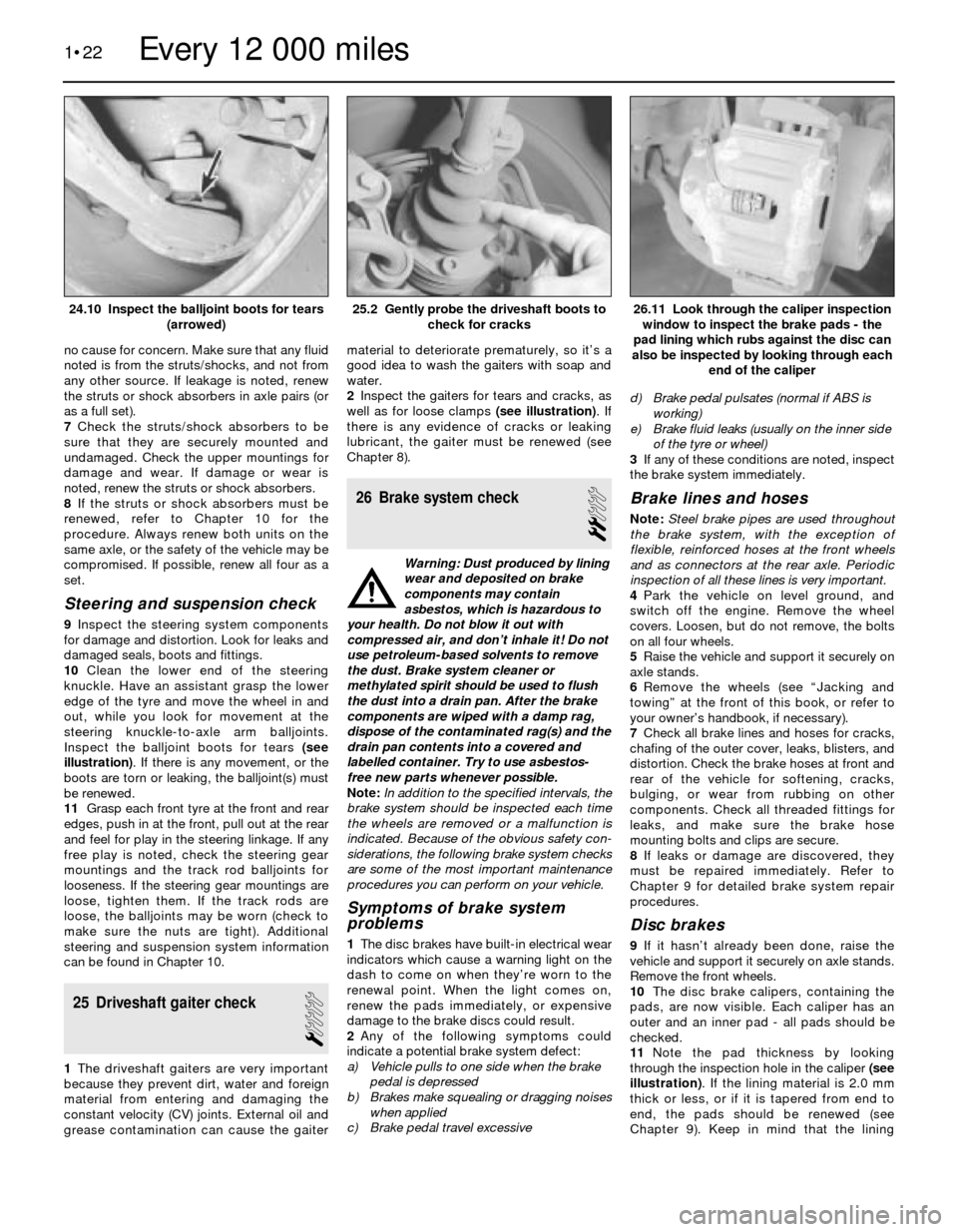
Inspect the balljoint boots for tears (see
illustration). If there is any movement, or the
boots are torn or leaking, the balljoint(s) must
be renewed.
11Grasp each front tyre at the front and rear
edges, push in at the front, pull out at the rear
and feel for play in the steering linkage. If any
free play is noted, check the steering gear
mountings and the track rod balljoints for
looseness. If the steering gear mountings are
loose, tighten them. If the track rods are
loose, the balljoints may be worn (check to
make sure the nuts are tight). Additional
steering and suspension system information
can be found in Chapter 10.
25 Driveshaft gaiter check
1
1The driveshaft gaiters are very important
because they prevent dirt, water and foreign
material from entering and damaging the
constant velocity (CV) joints. External oil and
grease contamination can cause the gaitermaterial to deteriorate prematurely, so it’s a
good idea to wash the gaiters with soap and
water.
2Inspect the gaiters for tears and cracks, as
well as for loose clamps (see illustration). If
there is any evidence of cracks or leaking
lubricant, the gaiter must be renewed (see
Chapter 8).
26 Brake system check
2
Warning: Dust produced by lining
wear and deposited on brake
components may contain
asbestos, which is hazardous to
your health. Do not blow it out with
compressed air, and don’t inhale it! Do not
use petroleum-based solvents to remove
the dust. Brake system cleaner or
methylated spirit should be used to flush
the dust into a drain pan. After the brake
components are wiped with a damp rag,
dispose of the contaminated rag(s) and the
drain pan contents into a covered and
labelled container. Try to use asbestos-
free new parts whenever possible.
Note:In addition to the specified intervals, the
brake system should be inspected each time
the wheels are removed or a malfunction is
indicated. Because of the obvious safety con-
siderations, the following brake system checks
are some of the most important maintenance
procedures you can perform on your vehicle.
Symptoms of brake system
problems
1The disc brakes have built-in electrical wear
indicators which cause a warning light on the
dash to come on when they’re worn to the
renewal point. When the light comes on,
renew the pads immediately, or expensive
damage to the brake discs could result.
2Any of the following symptoms could
indicate a potential brake system defect:
a) Vehicle pulls to one side when the brake
pedal is depressed
b) Brakes make squealing or dragging noises
when applied
c) Brake pedal travel excessived) Brake pedal pulsates (normal if ABS is
working)
e) Brake fluid leaks (usually on the inner side
of the tyre or wheel)
3If any of these conditions are noted, inspect
the brake system immediately.
Brake lines and hoses
Note: Steel brake pipes are used throughout
the brake system, with the exception of
flexible, reinforced hoses at the front wheels
and as connectors at the rear axle. Periodic
inspection of all these lines is very important.
4Park the vehicle on level ground, and
switch off the engine. Remove the wheel
covers. Loosen, but do not remove, the bolts
on all four wheels.
5Raise the vehicle and support it securely on
axle stands.
6Remove the wheels (see “Jacking and
towing” at the front of this book, or refer to
your owner’s handbook, if necessary).
7Check all brake lines and hoses for cracks,
chafing of the outer cover, leaks, blisters, and
distortion. Check the brake hoses at front and
rear of the vehicle for softening, cracks,
bulging, or wear from rubbing on other
components. Check all threaded fittings for
leaks, and make sure the brake hose
mounting bolts and clips are secure.
8If leaks or damage are discovered, they
must be repaired immediately. Refer to
Chapter 9 for detailed brake system repair
procedures.
Disc brakes
9If it hasn’t already been done, raise the
vehicle and support it securely on axle stands.
Remove the front wheels.
10The disc brake calipers, containing the
pads, are now visible. Each caliper has an
outer and an inner pad - all pads should be
checked.
11Note the pad thickness by looking
through the inspection hole in the caliper (see
illustration). If the lining material is 2.0 mm
thick or less, or if it is tapered from end to
end, the pads should be renewed (see
Chapter 9). Keep in mind that the lining
1•22
26.11 Look through the caliper inspection
window to inspect the brake pads - the
pad lining which rubs against the disc can
also be inspected by looking through each
end of the caliper25.2 Gently probe the driveshaft boots to
check for cracks24.10 Inspect the balljoint boots for tears
(arrowed)
Every 12 000 miles
Page 41 of 228
5On carburettor engines, remove the
complete air cleaner assembly (see Chap-
ter 4).
6Disconnect the coolant hoses from the
throttle body/intake manifold as applicable.
7Disconnect the throttle cable and, if
applicable, cruise control cable (see Chap-
ter 4).
8Remove the EGR valve and line where
applicable (see Chapter 6).
9At this stage on the M40 engine, the upper
part of the intake manifold should be removed
by unscrewing the bolts and nuts. Remove
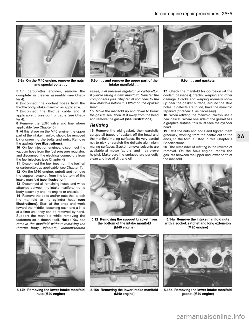
the gaskets (see illustrations).
10On fuel injection engines, disconnect the
vacuum hose from the fuel pressure regulator,
and disconnect the electrical connectors from
the fuel injectors (see Chapter 4).
11Disconnect the fuel lines from the fuel rail
or carburettor, as applicable (see Chapter 4).
12On the M40 engine, unbolt and remove
the support bracket from the bottom of the
intake manifold (see illustration).
13Disconnect all remaining hoses and wires
attached between the intake manifold/throttle
body assembly and the engine or chassis.
14Remove the bolts and/or nuts that attach
the manifold to the cylinder head (see
illustrations). Start at the ends and work
toward the middle, loosening each one a little
at a time until they can be removed by hand.
Support the manifold while removing the
fasteners so it doesn’t fall. Note: You can
remove the manifold without removing the
throttle body, injectors, vacuum/thermovalves, fuel pressure regulator or carburettor.
If you’re fitting a new manifold, transfer the
components (see Chapter 4) and lines to the
new manifold before it is fitted on the cylinder
head.
15Move the manifold up and down to break
the gasket seal, then lift it away from the head
and remove the gasket (see illustrations).
Refitting
16Remove the old gasket, then carefully
scrape all traces of sealant off the head and
the manifold mating surfaces. Be very careful
not to nick or scratch the delicate aluminium
mating surfaces. Gasket removal solvents are
available at motor factors, and may prove
helpful. Make sure the surfaces are perfectly
clean and free of dirt and oil.17Check the manifold for corrosion (at the
coolant passages), cracks, warping and other
damage. Cracks and warping normally show
up near the gasket surface, around the stud
holes. If defects are found, have the manifold
repaired (or renew it, as necessary).
18When refitting the manifold, always use a
new gasket. Where one side of the gasket has
a graphite surface, this must face the cylinder
head.
19Refit the nuts and bolts and tighten them
gradually, working from the centre out to the
ends, to the torque listed in this Chapter’s
Specifications.
20The remainder of refitting is the reverse of
removal. On the M40 engine, renew the
gaskets between the upper and lower parts of
the manifold.
In-car engine repair procedures 2A•5
5.9c . . . and gaskets5.9b . . . and remove the upper part of the
intake manifold . . .5.9a On the M40 engine, remove the nuts
and special bolts . . .
5.15b Removing the lower intake manifold
gasket (M40 engine)5.15a Removing the lower intake manifold
(M40 engine)
5.14a Remove the intake manifold nuts
with a socket, ratchet and long extension
(M20 engine)5.12 Removing the support bracket from
the bottom of the intake manifold
(M40 engine)
5.14b Removing the lower intake manifold
nuts (M40 engine)
2A
Page 42 of 228
6 Exhaust manifold-
removal and refitting
1
Warning: Make sure the engine is
completely cool before beginning
work on the exhaust system.
Caution: If the radio in your
vehicle is equipped with an anti-
theft system, make sure you
have the correct activation code
before disconnecting the battery.
Note: If, after connecting the battery, the
wrong language appears on the instrument
panel display, refer to page 0-7 for the
language resetting procedure.
1Disconnect the battery negative cable.
2On models where the air cleaner is on the
exhaust manifold side of the engine, remove
the air cleaner housing assembly and/or
airflow sensor to provide sufficient working
area (see Chapter 4, if necessary).
3Unplug the HT leads and set the spark plug
lead harness aside (see Chapter 1).
4Clearly label, then disconnect or remove, all
wires, hoses, fittings, etc. that are in the way.
Be sure to disconnect the oxygen sensor,
where fitted.
5Raise the vehicle, and support it securely
on axle stands. Working from under the
vehicle, separate the exhaust downpipe from
the manifold. Use penetrating oil on the
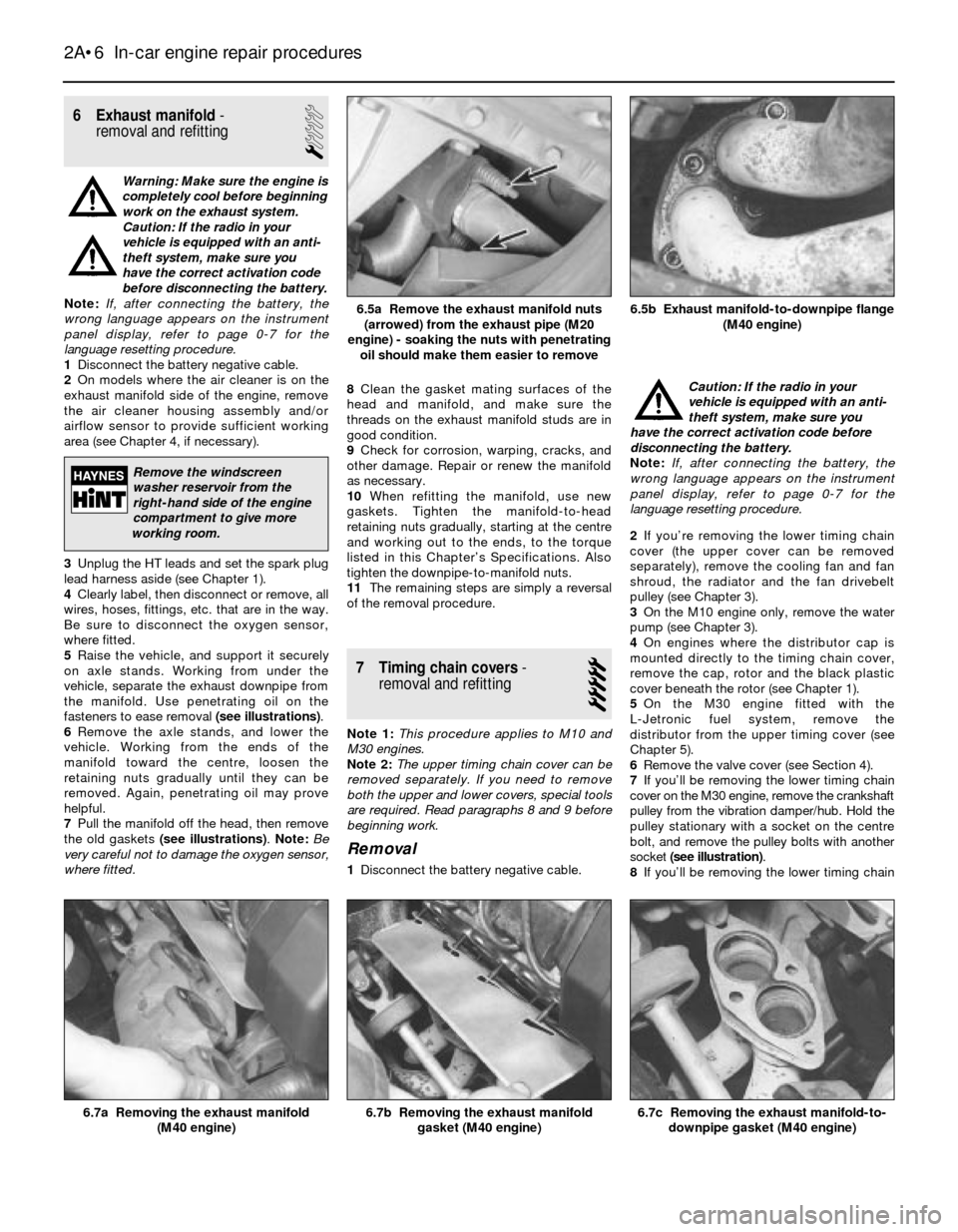
fasteners to ease removal (see illustrations).
6Remove the axle stands, and lower the
vehicle. Working from the ends of the
manifold toward the centre, loosen the
retaining nuts gradually until they can be
removed. Again, penetrating oil may prove
helpful.
7Pull the manifold off the head, then remove
the old gaskets (see illustrations). Note:Be
very careful not to damage the oxygen sensor,
where fitted.8Clean the gasket mating surfaces of the
head and manifold, and make sure the
threads on the exhaust manifold studs are in
good condition.
9Check for corrosion, warping, cracks, and
other damage. Repair or renew the manifold
as necessary.
10When refitting the manifold, use new
gaskets. Tighten the manifold-to-head
retaining nuts gradually, starting at the centre
and working out to the ends, to the torque
listed in this Chapter’s Specifications. Also
tighten the downpipe-to-manifold nuts.
11The remaining steps are simply a reversal
of the removal procedure.
7 Timing chain covers-
removal and refitting
5
Note 1:This procedure applies to M10 and
M30 engines.
Note 2:The upper timing chain cover can be
removed separately. If you need to remove
both the upper and lower covers, special tools
are required. Read paragraphs 8 and 9 before
beginning work.
Removal
1Disconnect the battery negative cable.Caution: If the radio in your
vehicle is equipped with an anti-
theft system, make sure you
have the correct activation code before
disconnecting the battery.
Note: If, after connecting the battery, the
wrong language appears on the instrument
panel display, refer to page 0-7 for the
language resetting procedure.
2If you’re removing the lower timing chain
cover (the upper cover can be removed
separately), remove the cooling fan and fan
shroud, the radiator and the fan drivebelt
pulley (see Chapter 3).
3On the M10 engine only, remove the water
pump (see Chapter 3).
4On engines where the distributor cap is
mounted directly to the timing chain cover,
remove the cap, rotor and the black plastic
cover beneath the rotor (see Chapter 1).
5On the M30 engine fitted with the
L-Jetronic fuel system, remove the
distributor from the upper timing cover (see
Chapter 5).
6Remove the valve cover (see Section 4).
7If you’ll be removing the lower timing chain
cover on the M30 engine, remove the crankshaft
pulley from the vibration damper/hub. Hold the
pulley stationary with a socket on the centre
bolt, and remove the pulley bolts with another
socket (see illustration).
8If you’ll be removing the lower timing chain
2A•6 In-car engine repair procedures
6.7c Removing the exhaust manifold-to-
downpipe gasket (M40 engine)6.7b Removing the exhaust manifold
gasket (M40 engine)6.7a Removing the exhaust manifold
(M40 engine)
6.5b Exhaust manifold-to-downpipe flange
(M40 engine)6.5a Remove the exhaust manifold nuts
(arrowed) from the exhaust pipe (M20
engine) - soaking the nuts with penetrating
oil should make them easier to remove
Remove the windscreen
washer reservoir from the
right-hand side of the engine
compartment to give more
working room.
Page 46 of 228
alignment mark on the camshaft sprocket and
rear timing cover to ensure correct refitting.
6On the M20 engine, loosen the two
tensioner roller retaining bolts a little, and
push the tensioner towards the water pump
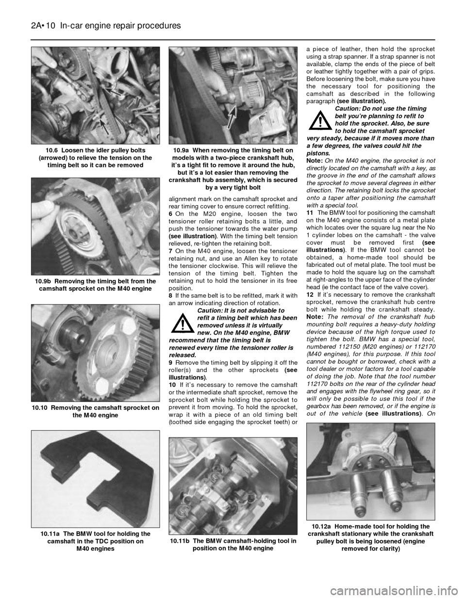
(see illustration). With the timing belt tension
relieved, re-tighten the retaining bolt.
7On the M40 engine, loosen the tensioner
retaining nut, and use an Allen key to rotate
the tensioner clockwise. This will relieve the
tension of the timing belt. Tighten the
retaining nut to hold the tensioner in its free
position.
8If the same belt is to be refitted, mark it with
an arrow indicating direction of rotation.
Caution: It is not advisable to
refit a timing belt which has been
removed unless it is virtually
new. On the M40 engine, BMW
recommend that the timing belt is
renewed every time the tensioner roller is
released.
9Remove the timing belt by slipping it off the
roller(s) and the other sprockets (see
illustrations).
10If it’s necessary to remove the camshaft
or the intermediate shaft sprocket, remove the
sprocket bolt while holding the sprocket to
prevent it from moving. To hold the sprocket,
wrap it with a piece of an old timing belt
(toothed side engaging the sprocket teeth) ora piece of leather, then hold the sprocket
using a strap spanner. If a strap spanner is not
available, clamp the ends of the piece of belt
or leather tightly together with a pair of grips.
Before loosening the bolt, make sure you have
the necessary tool for positioning the
camshaft as described in the following
paragraph (see illustration).
Caution: Do not use the timing
belt you’re planning to refit to
hold the sprocket. Also, be sure
to hold the camshaft sprocket
very steady, because if it moves more than
a few degrees, the valves could hit the
pistons.
Note: On the M40 engine, the sprocket is not
directly located on the camshaft with a key, as
the groove in the end of the camshaft allows
the sprocket to move several degrees in either
direction. The retaining bolt locks the sprocket
onto a taper after positioning the camshaft
with a special tool.
11The BMW tool for positioning the camshaft
on the M40 engine consists of a metal plate
which locates over the square lug near the No
1 cylinder lobes on the camshaft - the valve
cover must be removed first (see
illustrations). If the BMW tool cannot be
obtained, a home-made tool should be
fabricated out of metal plate. The tool must be
made to hold the square lug on the camshaft
at right-angles to the upper face of the cylinder
head (ie the contact face of the valve cover).
12If it’s necessary to remove the crankshaft
sprocket, remove the crankshaft hub centre
bolt while holding the crankshaft steady.
Note:The removal of the crankshaft hub
mounting bolt requires a heavy-duty holding
device because of the high torque used to
tighten the bolt. BMW has a special tool,
numbered 112150 (M20 engines) or 112170
(M40 engines), for this purpose. If this tool
cannot be bought or borrowed, check with a
tool dealer or motor factors for a tool capable
of doing the job. Note that the tool number
112170 bolts on the rear of the cylinder head
and engages with the flywheel ring gear, so it
will only be possible to use this tool if the
gearbox has been removed, or if the engine is
out of the vehicle (see illustrations). On
2A•10 In-car engine repair procedures
10.12a Home-made tool for holding the
crankshaft stationary while the crankshaft
pulley bolt is being loosened (engine
removed for clarity)
10.11b The BMW camshaft-holding tool in
position on the M40 engine10.11a The BMW tool for holding the
camshaft in the TDC position on
M40 engines
10.10 Removing the camshaft sprocket on
the M40 engine
10.9b Removing the timing belt from the
camshaft sprocket on the M40 engine
10.9a When removing the timing belt on
models with a two-piece crankshaft hub,
it’s a tight fit to remove it around the hub,
but it’s a lot easier than removing the
crankshaft hub assembly, which is secured
by a very tight bolt10.6 Loosen the idler pulley bolts
(arrowed) to relieve the tension on the
timing belt so it can be removed
Page 48 of 228
applied. Tighten the retaining nut to the
specified torque to hold the tensioner in its
correct position. Note:It is important that the
timing belt is tensioned correctly. If the belt is
over-tightened, it will howl, and there is the
possibility of it being damaged. If the belt is
too slack, it may jump on the sprockets.
24Check to make sure the camshaft and
crankshaft timing marks are still aligned(see
illustrations 10.5a and 10.5b).
25Turn the crankshaft clockwise through
two complete revolutions. (Remove the
camshaft positioning tool from the M40
engine first.)
Caution: This is necessary to
stretch the new belt. If not done,
the belt tensioner will be too
loose, and damage could result.
26On the M20 engine, loosen the tensioner
roller bolts, then tighten them to the torque
listed in this Chapter’s Specifications.
27On the M40 engine, loosen the tensioner
roller retaining nut, and re-adjust the tension
of the timing belt as described in paragraph
23. On completion, tighten the tensioner roller
retaining nut, then fully tighten the camshaft
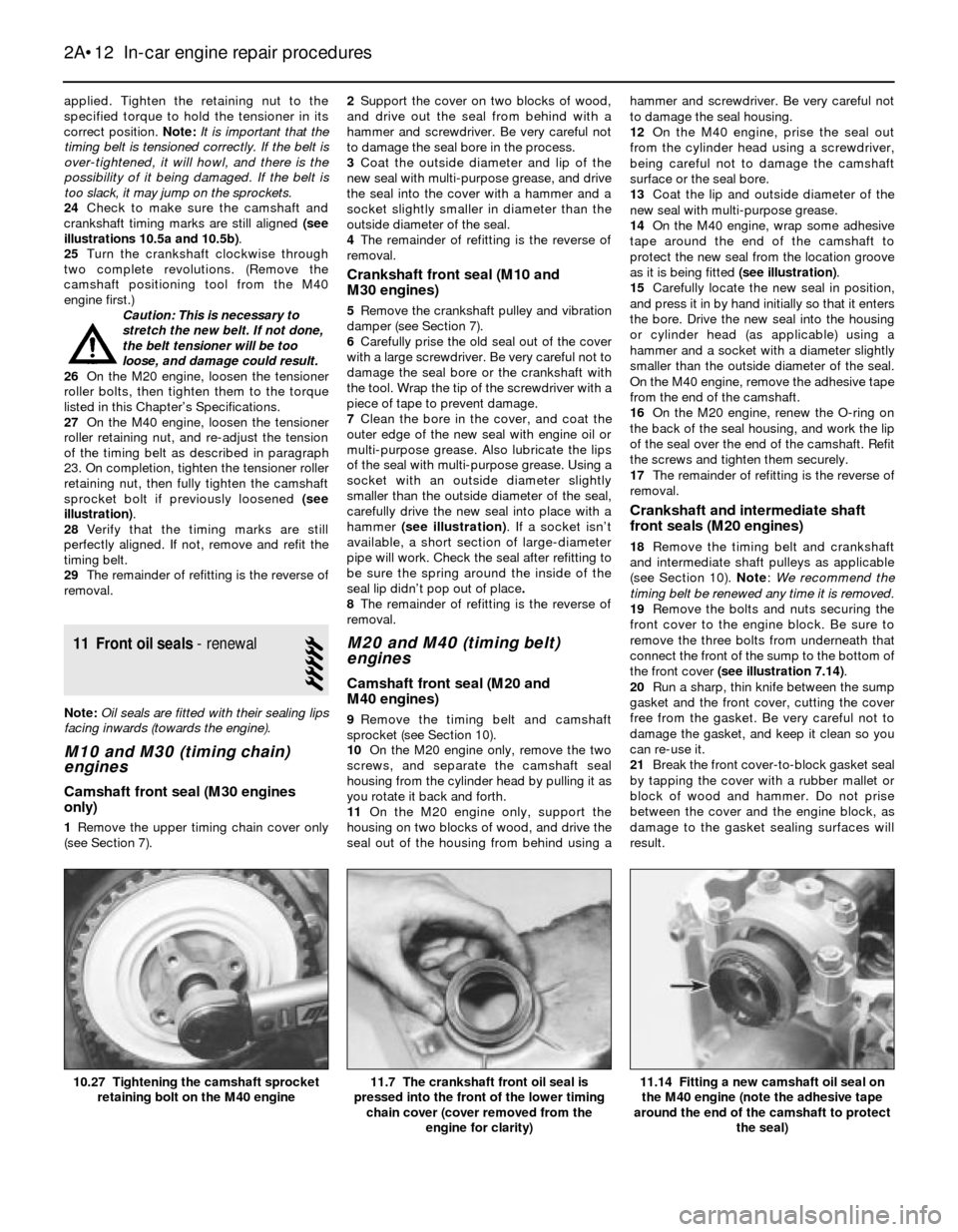
sprocket bolt if previously loosened (see
illustration).
28Verify that the timing marks are still
perfectly aligned. If not, remove and refit the
timing belt.
29The remainder of refitting is the reverse of
removal.
11 Front oil seals- renewal
5
Note:Oil seals are fitted with their sealing lips
facing inwards (towards the engine).
M10 and M30 (timing chain)
engines
Camshaft front seal (M30 engines
only)
1Remove the upper timing chain cover only
(see Section 7).2Support the cover on two blocks of wood,
and drive out the seal from behind with a
hammer and screwdriver. Be very careful not
to damage the seal bore in the process.
3Coat the outside diameter and lip of the
new seal with multi-purpose grease, and drive
the seal into the cover with a hammer and a
socket slightly smaller in diameter than the
outside diameter of the seal.
4The remainder of refitting is the reverse of
removal.
Crankshaft front seal (M10 and
M30 engines)
5Remove the crankshaft pulley and vibration
damper (see Section 7).
6Carefully prise the old seal out of the cover
with a large screwdriver. Be very careful not to
damage the seal bore or the crankshaft with
the tool. Wrap the tip of the screwdriver with a
piece of tape to prevent damage.
7Clean the bore in the cover, and coat the
outer edge of the new seal with engine oil or
multi-purpose grease. Also lubricate the lips
of the seal with multi-purpose grease. Using a
socket with an outside diameter slightly
smaller than the outside diameter of the seal,
carefully drive the new seal into place with a
hammer (see illustration). If a socket isn’t
available, a short section of large-diameter
pipe will work. Check the seal after refitting to
be sure the spring around the inside of the
seal lip didn’t pop out of place.
8The remainder of refitting is the reverse of
removal.
M20 and M40 (timing belt)
engines
Camshaft front seal (M20 and
M40 engines)
9Remove the timing belt and camshaft
sprocket (see Section 10).
10On the M20 engine only, remove the two
screws, and separate the camshaft seal
housing from the cylinder head by pulling it as
you rotate it back and forth.
11On the M20 engine only, support the
housing on two blocks of wood, and drive the
seal out of the housing from behind using ahammer and screwdriver. Be very careful not
to damage the seal housing.
12On the M40 engine, prise the seal out
from the cylinder head using a screwdriver,
being careful not to damage the camshaft
surface or the seal bore.
13Coat the lip and outside diameter of the
new seal with multi-purpose grease.
14On the M40 engine, wrap some adhesive
tape around the end of the camshaft to
protect the new seal from the location groove
as it is being fitted (see illustration).
15Carefully locate the new seal in position,
and press it in by hand initially so that it enters
the bore. Drive the new seal into the housing
or cylinder head (as applicable) using a
hammer and a socket with a diameter slightly
smaller than the outside diameter of the seal.
On the M40 engine, remove the adhesive tape
from the end of the camshaft.
16On the M20 engine, renew the O-ring on
the back of the seal housing, and work the lip
of the seal over the end of the camshaft. Refit
the screws and tighten them securely.
17The remainder of refitting is the reverse of
removal.
Crankshaft and intermediate shaft
front seals (M20 engines)
18Remove the timing belt and crankshaft
and intermediate shaft pulleys as applicable
(see Section 10). Note:We recommend the
timing belt be renewed any time it is removed.
19Remove the bolts and nuts securing the
front cover to the engine block. Be sure to
remove the three bolts from underneath that
connect the front of the sump to the bottom of
the front cover (see illustration 7.14).
20Run a sharp, thin knife between the sump
gasket and the front cover, cutting the cover
free from the gasket. Be very careful not to
damage the gasket, and keep it clean so you
can re-use it.
21Break the front cover-to-block gasket seal
by tapping the cover with a rubber mallet or
block of wood and hammer. Do not prise
between the cover and the engine block, as
damage to the gasket sealing surfaces will
result.
2A•12 In-car engine repair procedures
11.14 Fitting a new camshaft oil seal on
the M40 engine (note the adhesive tape
around the end of the camshaft to protect
the seal)11.7 The crankshaft front oil seal is
pressed into the front of the lower timing
chain cover (cover removed from the
engine for clarity)10.27 Tightening the camshaft sprocket
retaining bolt on the M40 engine