tow bar BMW 3 SERIES 1983 E30 Workshop Manual
[x] Cancel search | Manufacturer: BMW, Model Year: 1983, Model line: 3 SERIES, Model: BMW 3 SERIES 1983 E30Pages: 228, PDF Size: 7.04 MB
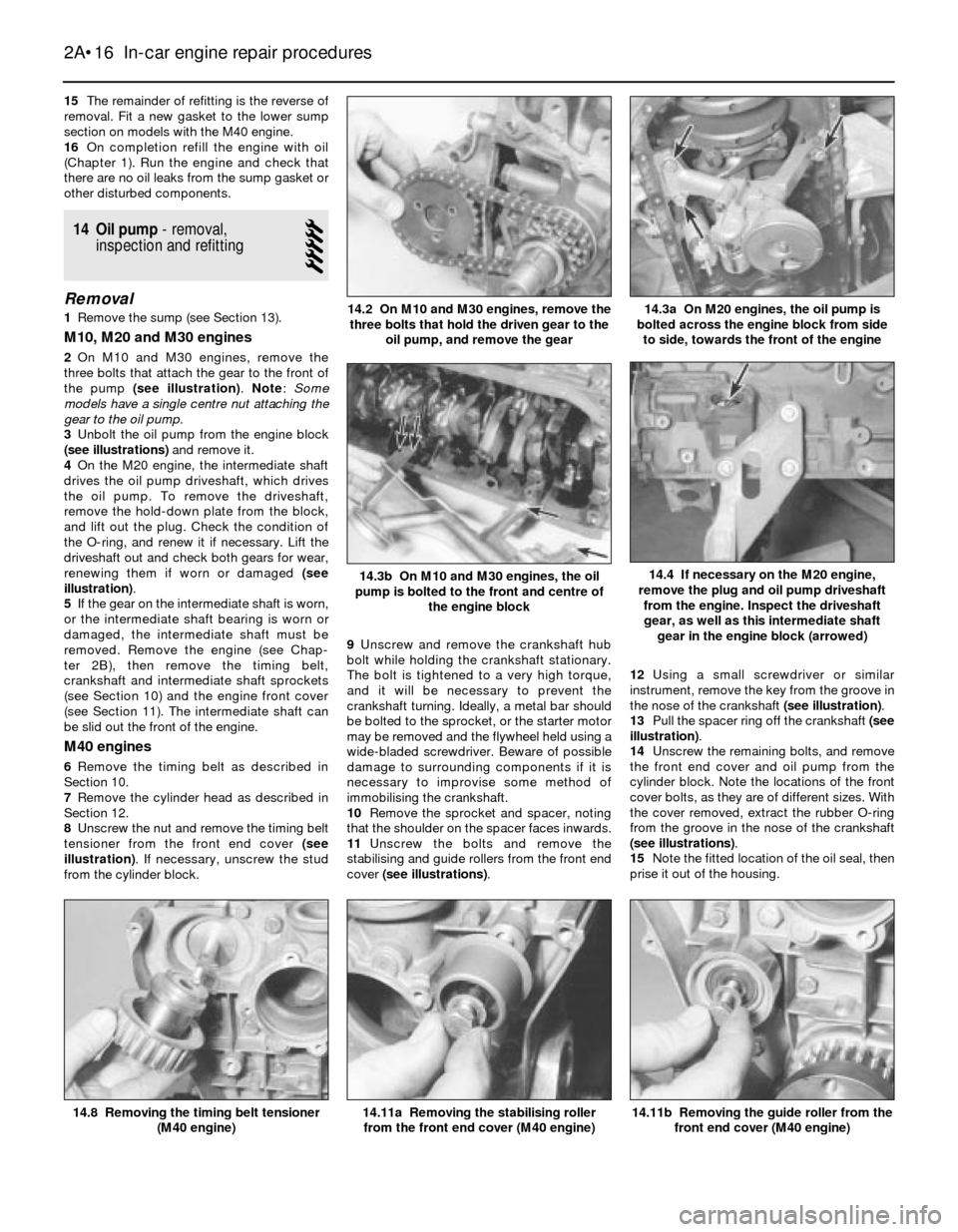
Page 52 of 228

15The remainder of refitting is the reverse of
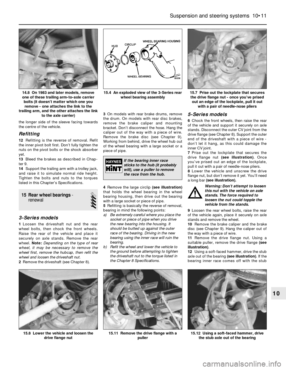
removal. Fit a new gasket to the lower sump
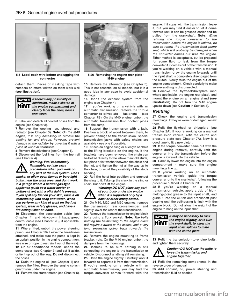
section on models with the M40 engine.
16On completion refill the engine with oil
(Chapter 1). Run the engine and check that
there are no oil leaks from the sump gasket or
other disturbed components.
14 Oil pump- removal,
inspection and refitting
5
Removal
1Remove the sump (see Section 13).
M10, M20 and M30 engines
2On M10 and M30 engines, remove the
three bolts that attach the gear to the front of
the pump (see illustration). Note: Some
models have a single centre nut attaching the
gear to the oil pump.
3Unbolt the oil pump from the engine block
(see illustrations)and remove it.
4On the M20 engine, the intermediate shaft
drives the oil pump driveshaft, which drives
the oil pump. To remove the driveshaft,
remove the hold-down plate from the block,
and lift out the plug. Check the condition of
the O-ring, and renew it if necessary. Lift the
driveshaft out and check both gears for wear,
renewing them if worn or damaged (see
illustration).
5If the gear on the intermediate shaft is worn,
or the intermediate shaft bearing is worn or
damaged, the intermediate shaft must be
removed. Remove the engine (see Chap-
ter 2B), then remove the timing belt,
crankshaft and intermediate shaft sprockets
(see Section 10) and the engine front cover
(see Section 11). The intermediate shaft can
be slid out the front of the engine.
M40 engines
6Remove the timing belt as described in
Section 10.
7Remove the cylinder head as described in
Section 12.
8Unscrew the nut and remove the timing belt
tensioner from the front end cover (see
illustration). If necessary, unscrew the stud
from the cylinder block.9Unscrew and remove the crankshaft hub
bolt while holding the crankshaft stationary.
The bolt is tightened to a very high torque,
and it will be necessary to prevent the
crankshaft turning. Ideally, a metal bar should
be bolted to the sprocket, or the starter motor
may be removed and the flywheel held using a
wide-bladed screwdriver. Beware of possible
damage to surrounding components if it is
necessary to improvise some method of
immobilising the crankshaft.
10Remove the sprocket and spacer, noting
that the shoulder on the spacer faces inwards.
11Unscrew the bolts and remove the
stabilising and guide rollers from the front end
cover (see illustrations).12Using a small screwdriver or similar
instrument, remove the key from the groove in
the nose of the crankshaft (see illustration).
13Pull the spacer ring off the crankshaft (see
illustration).
14Unscrew the remaining bolts, and remove
the front end cover and oil pump from the
cylinder block. Note the locations of the front
cover bolts, as they are of different sizes. With
the cover removed, extract the rubber O-ring
from the groove in the nose of the crankshaft
(see illustrations).
15Note the fitted location of the oil seal, then
prise it out of the housing.
2A•16 In-car engine repair procedures
14.11b Removing the guide roller from the
front end cover (M40 engine)14.11a Removing the stabilising roller
from the front end cover (M40 engine)14.8 Removing the timing belt tensioner
(M40 engine)
14.3b On M10 and M30 engines, the oil
pump is bolted to the front and centre of
the engine block14.4 If necessary on the M20 engine,
remove the plug and oil pump driveshaft
from the engine. Inspect the driveshaft
gear, as well as this intermediate shaft
gear in the engine block (arrowed)
14.3a On M20 engines, the oil pump is
bolted across the engine block from side
to side, towards the front of the engine14.2 On M10 and M30 engines, remove the
three bolts that hold the driven gear to the
oil pump, and remove the gear
Page 62 of 228

detach them. Pieces of masking tape with
numbers or letters written on them work well
(see illustration).
6Label and detach all coolant hoses from the
engine (see Chapter 3).
7Remove the cooling fan, shroud and
radiator (see Chapter 3). Note:On the M40
engine, it is only necessary to remove the
cooling fan and shroud; however, prevent
damage to the radiator by covering it with a
piece of wood or cardboard.
8Remove the drivebelts (see Chapter 1).
9Disconnect the fuel lines from the fuel rail
(see Chapter 4).
Warning: Fuel is extremely
flammable, so take extra
precautions when you work on
any part of the fuel system. Don’t
smoke, or allow open flames or bare light
bulbs, near the work area, and don’t work
in a garage where a natural gas-type
appliance (such as a water heater or
clothes dryer) with a pilot light is present.
If you spill any fuel on your skin, rinse it off
immediately with soap and water. When
you perform any kind of work on the fuel
system, wear safety glasses, and have a
fire extinguisher on hand.
10Disconnect the accelerator cable (see
Chapter 4) and kickdown linkage/speed
control cable (see Chapter 7B), if applicable,
from the engine.
11Where fitted, unbolt the power steering
pump (see Chapter 10). Leave the lines/hoses
attached, and make sure the pump is kept in
an upright position in the engine compartment
(use wire or rope to restrain it out of the way).
12On air-conditioned models, unbolt the
compressor (see Chapter 3) and set it aside,
or tie it up out of the way. Do not disconnect
the hoses.
13Drain the engine oil (see Chapter 1) and
remove the filter. Remove the engine splash
guard from under the engine.
14Remove the starter motor (see Chapter 5).15Remove the alternator (see Chapter 5).
This is not essential on all models, but it is a
good idea in any case to avoid accidental
damage.
16Unbolt the exhaust system from the
engine (see Chapter 4).
17If you’re working on a vehicle with an
automatic transmission, remove the torque
converter-to-driveplate fasteners (see
Chapter 7B). On the M40 engine, unbolt the
automatic transmission fluid coolant pipes
from the sump.
18Support the transmission with a jack.
Position a block of wood between them, to
prevent damage to the transmission. Special
transmission jacks with safety chains are
available - use one if possible.
19Attach an engine sling or a length of chain
to the lifting brackets on the engine. If the
brackets have been removed, the chain can
be bolted directly to the intake manifold studs,
but place a flat washer between the chain and
the nut, and tighten the nut all the way up to
the chain, to avoid the possibility of the studs
bending.
20Roll the hoist into position and connect
the sling to it. Take up the slack in the sling or
chain, but don’t lift the engine.
Warning: DO NOT place any part
of your body under the engine
when it’s supported only by a
hoist or other lifting device.
21On M10, M20 and M30 engines, remove
the transmission rear crossmember, and
slightly lower the rear of the transmission.
22Remove the transmission-to-engine block
bolts using a Torx socket. Note:The bolts
holding the bellhousing to the engine block
will require a swivel at the socket, and a very
long extension going back towards the
transmission.
23Remove the engine mounting-to-frame
bracket nuts. On the M40 engine, unbolt the
dampers from the mountings.
24Recheck to be sure nothing is still
connecting the engine to the transmission or
vehicle. Disconnect anything still remaining.
25Raise the engine slightly. Carefully work it
forwards to separate it from the transmission.
If you’re working on a vehicle with an
automatic transmission, you may find the
torque converter comes forward with theengine. If it stays with the transmission, leave
it, but you may find it easier to let it come
forward until it can be grasped easier and be
pulled from the crankshaft. Note:When
refitting the torque converter to the
transmission before the engine is refitted, be
sure to renew the transmission front pump
seal, which will probably be damaged when
the converter comes out with the engine.
Either method is acceptable, but be prepared
for some fluid to leak from the torque
converter if it comes out of the transmission. If
you’re working on a vehicle with a manual
transmission, draw the engine forwards until
the input shaft is completely disengaged from
the clutch. Slowly raise the engine out of the
engine compartment. Check carefully to make
sure everything is disconnected.
26Remove the flywheel/driveplate (and
where applicable, the engine rear plate), and
mount the engine on an engine stand (see
illustration). Do not turn the M40 engine
upside-down (see Cautionin Section 4).
Refitting
27Check the engine and transmission
mountings. If they’re worn or damaged, renew
them.
28Refit the flywheel or driveplate (see
Chapter 2A). If you’re working on a manual
transmission vehicle, refit the clutch and
pressure plate (see Chapter 7A). Now is a
good time to fit a new clutch.
29If the torque converter came out with the
engine during removal, carefully refit the
converter into the transmission before the
engine is lowered into the vehicle.
30Carefully lower the engine into the engine
compartment - make sure the engine
mountings line up.
31If you’re working on an automatic
transmission vehicle, guide the torque
converter onto the crankshaft following the
procedure outlined in Chapter 7B.
32If you’re working on a manual
transmission vehicle, apply a dab of high-
melting-point grease to the input shaft, and
guide it into the clutch and crankshaft pilot
bearing until the bellhousing is flush with the
engine block.. Do not allow the weight of the
engine to hang on the input shaft.
33Refit the transmission-to-engine bolts,
and tighten them securely.
Caution: DO NOT use the bolts to
force the transmission and
engine together.
34Refit the remaining components in the
reverse order of removal.
35Add coolant, oil, power steering and
transmission fluid as needed.
2B•6 General engine overhaul procedures
5.26 Removing the engine rear plate -
M40 engine5.5 Label each wire before unplugging the
connector
If there’s any possibility of
confusion, make a sketch of
the engine compartment and
clearly label the lines, hoses
and wires.
It may be necessary to rock
the engine slightly, or to turn
the crankshaft, to allow the
input shaft splines to mate
with the clutch plate
Page 79 of 228

3General
Coolant capacity . . . . . . . . . . . . . . . . . . . . . . . . . . . . . . . . . . . . . . . . . . . See Chapter 1
Thermostat rating
Opening temperature . . . . . . . . . . . . . . . . . . . . . . . . . . . . . . . . . . . . . 80°C (176°F)
Fully open at . . . . . . . . . . . . . . . . . . . . . . . . . . . . . . . . . . . . . . . . . . . . 100°C (212°F)
Cooling fan thermo-switch - switching temperatures
Low-speed . . . . . . . . . . . . . . . . . . . . . . . . . . . . . . . . . . . . . . . . . . . . . 91°C (196°F)
High-speed . . . . . . . . . . . . . . . . . . . . . . . . . . . . . . . . . . . . . . . . . . . . . 99°C (210°F)
Torque wrench settingsNm
Mechanical cooling fan clutch-to-water pump securing
nut (left-hand thread) . . . . . . . . . . . . . . . . . . . . . . . . . . . . . . . . . . . . 40
Mechanical cooling fan-to-clutch bolts . . . . . . . . . . . . . . . . . . . . . . . . . 10
Water pump bolts
Small bolts (M6) . . . . . . . . . . . . . . . . . . . . . . . . . . . . . . . . . . . . . . . . . 10
Large bolts (M8) . . . . . . . . . . . . . . . . . . . . . . . . . . . . . . . . . . . . . . . . . 22
Thermostat housing bolts . . . . . . . . . . . . . . . . . . . . . . . . . . . . . . . . . . . . 10
Chapter 3
Cooling, heating and air conditioning systems
Air conditioner receiver-drier - removal and refitting . . . . . . . . . . . . 16
Air conditioning blower motor (E28/”old-shape” 5-series
models) - removal and refitting . . . . . . . . . . . . . . . . . . . . . . . . . . . 14
Air conditioning compressor - removal and refitting . . . . . . . . . . . . . 13
Air conditioning condenser - removal and refitting . . . . . . . . . . . . . . 15
Air conditioning system - precautions and maintenance . . . . . . . . . 12
Antifreeze - general information . . . . . . . . . . . . . . . . . . . . . . . . . . . . 2
Coolant level check . . . . . . . . . . . . . . . . . . . . . . . . . . See Chapter 1
Coolant temperature sender unit - check and renewal . . . . . . . . . . . 8
Cooling system check . . . . . . . . . . . . . . . . . . . . . . . . See Chapter 1
Cooling system servicing (draining, flushing and refilling)See Chapter 1Engine cooling fan(s) and clutch - check, removal and refitting . . . . 5
Evaporator matrix - removal and refitting . . . . . . . . . . . . . . . . . . . . . 17
General information . . . . . . . . . . . . . . . . . . . . . . . . . . . . . . . . . . . . . . 1
Heater and air conditioner control assembly - removal and refitting 10
Heater and air conditioning blower motor - removal,testing and
refitting . . . . . . . . . . . . . . . . . . . . . . . . . . . . . . . . . . . . . . . . . . . . . . 9
Heater matrix - removal and refitting . . . . . . . . . . . . . . . . . . . . . . . . 11
Radiator - removal and refitting . . . . . . . . . . . . . . . . . . . . . . . . . . . . 4
Thermostat - check and renewal . . . . . . . . . . . . . . . . . . . . . . . . . . . 3
Water pump - check . . . . . . . . . . . . . . . . . . . . . . . . . . . . . . . . . . . . . 6
Water pump - removal and refitting . . . . . . . . . . . . . . . . . . . . . . . . . 7
3•1
Easy,suitable for
novice with little
experienceFairly easy,suitable
for beginner with
some experienceFairly difficult,
suitable for competent
DIY mechanic
Difficult,suitable for
experienced DIY
mechanicVery difficult,
suitable for expert
DIY or professional
Degrees of difficulty
Specifications Contents
1 General information
Engine cooling system
All vehicles covered by this manual employ
a pressurised engine cooling system, with
thermostatically-controlled coolant circulation.
An impeller-type water pump mounted on
the front of the block pumps coolant through
the engine. The coolant flows around each
cylinder, and towards the rear of the engine.
Cast-in coolant passages direct coolantaround the intake and exhaust ports, near the
spark plug areas, and in close proximity to the
exhaust valve guides.
A wax-pellet-type thermostat is located in-
line in the bottom hose on M10 engines, in a
housing near the front of the engine on M20
and M30 engines, or behind an elbow under
the timing belt upper cover (on the front of the
cylinder head) on M40 engines. During warm-
up, the closed thermostat prevents coolant
from circulating through the radiator. As the
engine nears normal operating temperature,
the thermostat opens and allows hot coolant
to travel through the radiator, where it’s
cooled before returning to the engine.The pressure in the system raises the
boiling point of the coolant, and increases the
cooling efficiency of the radiator. The cooling
system is sealed by a pressure-type cap. If
the system pressure exceeds the cap
pressure relief value, the excess pressure in
the system forces the spring-loaded valve
inside the cap off its seat, and allows the
coolant to escape through the overflow tube.
The pressure cap on four-cylinder models is
on the top of the radiator; on six-cylinder models,
it’s on top of a translucent plastic expansion
tank. The cap pressure rating is moulded into the
top of the cap. The pressure rating is either
1.0 bar (14 psi) or 1.2 bars (17 psi).
Page 153 of 228

the longer side of the sleeve facing towards
the centre of the vehicle.
Refitting
12Refitting is the reverse of removal. Refit
the inner pivot bolt first. Don’t fully tighten the
nuts on the pivot bolts or the shock absorber
yet.
13Bleed the brakes as described in Chap-
ter 9.
14Support the trailing arm with a trolley jack,
and raise it to simulate normal ride height.
Tighten the bolts and nuts to the torques
listed in this Chapter’s Specifications.
15 Rear wheel bearings-
renewal
4
3-Series models
1Loosen the driveshaft nut and the rear
wheel bolts, then chock the front wheels.
Raise the rear of the vehicle and place it
securely on axle stands. Remove the rear
wheel. Note: Depending on the type of rear
wheel, it may be necessary to remove the
wheel first, remove the hubcap, then refit the
wheel and loosen the driveshaft nut.
2Remove the driveshaft (see Chapter 8).3On models with rear brake drums, remove
the drum. On models with rear disc brakes,
remove the brake caliper and mounting
bracket. Don’t disconnect the hose. Hang the
caliper out of the way with a piece of wire.
Remove the brake disc (see Chapter 9).
Working from behind, drive the wheel hub out
of the wheel bearing with a large socket or a
piece of pipe.
4Remove the large circlip (see illustration)
that holds the wheel bearing in the wheel
bearing housing, then drive out the bearing
with a large socket or piece of pipe.
5Refitting is basically the reverse of removal,
bearing in mind the following points:
a) Be extremely careful where you place the
socket or piece of pipe when you drive
the new bearing into the housing. It
should be butted up against the outer
race of the bearing. Driving in the new
bearing using the inner race will ruin the
bearing.
b) Refit the wheel and lower the vehicle to
the ground before attempting to tighten
the driveshaft nut to the torque listed in
the Chapter 8 Specifications.
5-Series models
6Chock the front wheels, then raise the rear
of the vehicle and support it securely on axle
stands. Disconnect the outer CV joint from the
drive flange (see Chapter 8). Support the outer
end of the driveshaft with a piece of wire -
don’t let it hang, as this could damage the
inner CV joint.
7Prise out the lockplate that secures the
drive flange nut (see illustration). Once
you’ve prised out an edge of the lockplate,
pull it out with a pair of needle-nose pliers.
8Lower the vehicle and unscrew the drive
flange nut, but don’t remove it yet. You’ll need
a long bar (see illustration).
Warning: Don’t attempt to loosen
this nut with the vehicle on axle
stands. The force required to
loosen the nut could topple the
vehicle from the stands.
9Loosen the rear wheel bolts, raise the rear
of the vehicle again, place it securely on axle
stands and remove the wheel.
10Remove the brake caliper and the brake
disc (see Chapter 9). Hang the caliper out of
the way with a piece of wire.
11Remove the drive flange nut. Using a
suitable puller, remove the drive flange (see
illustration).
12Using a soft-faced hammer, drive the stub
axle out of the bearing (see illustration). If the
bearing inner race comes off with the stub
Suspension and steering systems 10•11
15.7 Prise out the lockplate that secures
the drive flange nut - once you’ve prised
out an edge of the lockplate, pull it out
with a pair of needle-nose pliers15.4 An exploded view of the 3-Series rear
wheel bearing assembly14.8 On 1983 and later models, remove
one of these trailing arm-to-axle carrier
bolts (it doesn’t matter which one you
remove - one attaches the link to the
trailing arm, and the other attaches the link
to the axle carrier)
15.12 Using a soft-faced hammer, drive
the stub axle out of the bearing15.11 Remove the drive flange with a
puller15.8 Lower the vehicle and loosen the
drive flange nut
10
If the bearing inner race
sticks to the hub (it probably
will), use a puller to remove
the race from the hub.