Chapter 2 BMW 3 SERIES 1984 E30 Workshop Manual
[x] Cancel search | Manufacturer: BMW, Model Year: 1984, Model line: 3 SERIES, Model: BMW 3 SERIES 1984 E30Pages: 228, PDF Size: 7.04 MB
Page 171 of 228
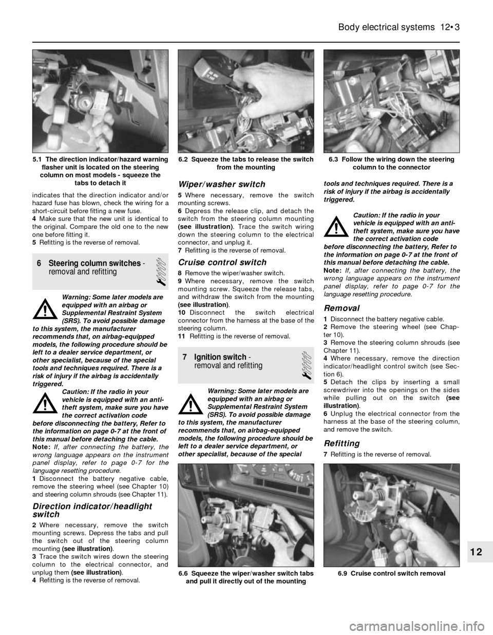
indicates that the direction indicator and/or
hazard fuse has blown, check the wiring for a
short-circuit before fitting a new fuse.
4Make sure that the new unit is identical to
the original. Compare the old one to the new
one before fitting it.
5Refitting is the reverse of removal.
6 Steering column switches-
removal and refitting
1
Warning: Some later models are
equipped with an airbag or
Supplemental Restraint System
(SRS). To avoid possible damage
to this system, the manufacturer
recommends that, on airbag-equipped
models, the following procedure should be
left to a dealer service department, or
other specialist, because of the special
tools and techniques required. There is a
risk of injury if the airbag is accidentally
triggered.
Caution: If the radio in your
vehicle is equipped with an anti-
theft system, make sure you have
the correct activation code
before disconnecting the battery, Refer to
the information on page 0-7 at the front of
this manual before detaching the cable.
Note: If, after connecting the battery, the
wrong language appears on the instrument
panel display, refer to page 0-7 for the
language resetting procedure.
1Disconnect the battery negative cable,
remove the steering wheel (see Chapter 10)
and steering column shrouds (see Chapter 11).
Direction indicator/headlight
switch
2Where necessary, remove the switch
mounting screws. Depress the tabs and pull
the switch out of the steering column
mounting (see illustration).
3Trace the switch wires down the steering
column to the electrical connector, and
unplug them (see illustration).
4Refitting is the reverse of removal.
Wiper/washer switch
5Where necessary, remove the switch
mounting screws.
6Depress the release clip, and detach the
switch from the steering column mounting
(see illustration). Trace the switch wiring
down the steering column to the electrical
connector, and unplug it.
7Refitting is the reverse of removal.
Cruise control switch
8Remove the wiper/washer switch.
9Where necessary, remove the switch
mounting screw. Squeeze the release tabs,
and withdraw the switch from the mounting
(see illustration).
10Disconnect the switch electrical
connector from the harness at the base of the
steering column.
11Refitting is the reverse of removal.
7 Ignition switch-
removal and refitting
1
Warning: Some later models are
equipped with an airbag or
Supplemental Restraint System
(SRS). To avoid possible damage
to this system, the manufacturer
recommends that, on airbag-equipped
models, the following procedure should be
left to a dealer service department, or
other specialist, because of the specialtools and techniques required. There is a
risk of injury if the airbag is accidentally
triggered.
Caution: If the radio in your
vehicle is equipped with an anti-
theft system, make sure you have
the correct activation code
before disconnecting the battery, Refer to
the information on page 0-7 at the front of
this manual before detaching the cable.
Note: If, after connecting the battery, the
wrong language appears on the instrument
panel display, refer to page 0-7 for the
language resetting procedure.
Removal
1Disconnect the battery negative cable.
2Remove the steering wheel (see Chap-
ter 10).
3Remove the steering column shrouds (see
Chapter 11).
4Where necessary, remove the direction
indicator/headlight control switch (see Sec-
tion 6).
5Detach the clips by inserting a small
screwdriver into the openings on the sides
while pulling out on the switch (see
illustration).
6Unplug the electrical connector from the
harness at the base of the steering column,
and remove the switch.
Refitting
7Refitting is the reverse of removal.
Body electrical systems 12•3
6.3 Follow the wiring down the steering
column to the connector6.2 Squeeze the tabs to release the switch
from the mounting
6.9 Cruise control switch removal6.6 Squeeze the wiper/washer switch tabs
and pull it directly out of the mounting
12
5.1 The direction indicator/hazard warning
flasher unit is located on the steering
column on most models - squeeze the
tabs to detach it
Page 172 of 228
8 Radio- removal and refitting
1
Caution: If the radio in your
vehicle is equipped with an anti-
theft system, make sure you have
the correct activation code
before disconnecting the battery, Refer to
the information on page 0-7 at the front of
this manual before detaching the cable.
Note: If, after connecting the battery, the
wrong language appears on the instrument
panel display, refer to page 0-7 for the
language resetting procedure.
Removal
1Disconnect the battery negative cable.
2The radios on most models are held in place
by internal clips which are usually located at
the sides or corners of the unit faceplate.
Removal requires a special tool which is
inserted into the holes to release the clips so
the radio can be pulled out. These tools can be
fabricated from heavy wire, or are available
from your dealer or a car audio specialist. On
anti-theft radios, the clips are moved in and
out by internal screws which require another
type of tool. Insert the tool into the holes until
the clips release, then withdraw the radio from
the dash panel. Disconnect the wiring from the
radio and remove it.3On some models, the radio is held in place
by screws located beneath the faceplate. The
control knobs must be pulled off before the
faceplate can be withdrawn.
Refitting
4Refitting is the reverse of removal.
9 Aerial- removal and refitting
1
Caution: If the radio in your
vehicle is equipped with an anti-
theft system, make sure you have
the correct activation code
before disconnecting the battery, Refer to
the information on page 0-7 at the front of
this manual before detaching the cable.
Note: If, after connecting the battery, the
wrong language appears on the instrument
panel display, refer to page 0-7 for the
language resetting procedure.
Removal
1Disconnect the battery negative cable.
2Use circlip pliers to unscrew the aerial
mounting nut.
3Open the boot lid/tailgate and remove the
left side trim panel. On some models, the jack
and tail light cluster cover will have to be
removed first.
4Unplug the aerial power and radio lead
connectors (as applicable), remove the
retaining bolts, and remove the aerial and
motor assembly.
Refitting
5Refitting is the reverse of removal.
10 Instrument cluster-
removal and refitting
2
Caution: The instrument cluster
and components are very
susceptible to damage from
static electricity. Make sure you
are earthed and have dischargedany static electricity (by touching an object
such as a metal water pipe) before
touching the cluster or components.
Caution: If the radio in your
vehicle is equipped with an anti-
theft system, make sure you have
the correct activation code
before disconnecting the battery, Refer to
the information on page 0-7 at the front of
this manual before detaching the cable.
Note: If, after connecting the battery, the
wrong language appears on the instrument
panel display, refer to page 0-7 for the
language resetting procedure.
Removal
1Disconnect the battery negative cable.
2As necessary, remove the steering column
shrouds and lower trim panel (see Chap-
ter 11).
3Remove the screws holding the cluster to
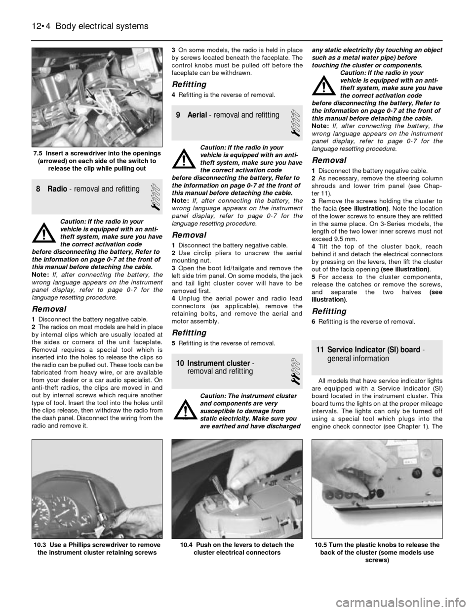
the facia (see illustration). Note the location
of the lower screws to ensure they are refitted
in the same place. On 3-Series models, the
length of the two lower inner screws must not
exceed 9.5 mm.
4Tilt the top of the cluster back, reach
behind it and detach the electrical connectors
by pressing on the levers, then lift the cluster
out of the facia opening (see illustration).
5For access to the cluster components,
release the catches or remove the screws,
and separate the two halves (see
illustration).
Refitting
6Refitting is the reverse of removal.
11 Service Indicator (SI) board-
general information
All models that have service indicator lights
are equipped with a Service Indicator (SI)
board located in the instrument cluster. This
board turns the lights on at the proper mileage
intervals. The lights can only be turned off
using a special tool which plugs into the
engine check connector (see Chapter 1). The
12•4 Body electrical systems
10.5 Turn the plastic knobs to release the
back of the cluster (some models use
screws)10.4 Push on the levers to detach the
cluster electrical connectors10.3 Use a Phillips screwdriver to remove
the instrument cluster retaining screws
7.5 Insert a screwdriver into the openings
(arrowed) on each side of the switch to
release the clip while pulling out
Page 173 of 228
SI board is a self-contained computer which
includes a chip and batteries.
The rechargeable SI board nickel cadmium
(nicad) batteries maintain power to the
computer memory in the event of a power
drop (such as during starting) or complete
power loss (such as a dead or disconnected
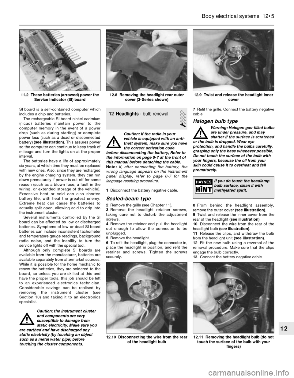
battery) (see illustration). This assures power
so the computer can continue to keep track of
mileage and turn the lights on at the proper
interval.
The batteries have a life of approximately
six years, at which time they must be replaced
with new ones. Also, since they are recharged
by the engine charging system, they can run
down prematurely if power is cut off for some
reason (such as a blown fuse, a fault in the
wiring, or extended storage of the vehicle).
Excessive heat or cold can also shorten
battery life, with heat the greatest enemy.
Extreme heat can cause the batteries to
actually split open, allowing acid to drip into
the instrument cluster.
Several instruments controlled by the SI
board can be affected by low or discharged
batteries. Symptoms of low or dead SI board
batteries can include inconsistent tachometer
and temperature gauge readings, background
radio noise, and the inability to turn the
service lights off with the special tool.
Although only complete SI boards are
available from the manufacturer, batteries are
available separately from aftermarket sources.
While it is possible for the home mechanic to
renew the batteries, they are soldered to the
board, so unless you are skilled at this and
have the proper tools, this job should be left
to an experienced electronics technician.
Considerable savings can be realised by
removing the instrument cluster (see
Section 10) and taking it to an electronics
specialist.
Caution: the instrument cluster
and components are very
susceptible to damage from
static electricity. Make sure you
are earthed and have discharged any
static electricity (by touching an object
such as a metal water pipe) before
touching the cluster components.12 Headlights- bulb renewal
1
Caution: If the radio in your
vehicle is equipped with an anti-
theft system, make sure you have
the correct activation code
before disconnecting the battery, Refer to
the information on page 0-7 at the front of
this manual before detaching the cable.
Note: If, after connecting the battery, the
wrong language appears on the instrument
panel display, refer to page 0-7 for the
language resetting procedure.
1Disconnect the battery negative cable.
Sealed-beam type
2Remove the grille (see Chapter 11).
3Remove the headlight retainer screws,
taking care not to disturb the adjustment
screws.
4Remove the retainer and pull the headlight
out enough to allow the connector to be
unplugged.
5Remove the headlight.
6To refit the headlight, plug the connector in,
place the headlight in position, and refit the
retainer and screws. Tighten the screws
securely.7Refit the grille. Connect the battery negative
cable.
Halogen bulb type
Warning: Halogen gas-filled bulbs
are under pressure, and may
shatter if the surface is scratched
or the bulb is dropped. Wear eye
protection, and handle the bulbs carefully,
grasping only the base whenever possible.
Do not touch the surface of the bulb with
your fingers, because the oil from your
skin could cause it to overheat and fail
prematurely.
8From behind the headlight assembly,
remove the outer cover (see illustration).
9Twist and release the inner cover from the
rear of the headlight (see illustration).
10Disconnect the wire from the rear of the
headlight bulb (see illustration).
11Release the clips, and withdraw the bulb
from the headlight unit (see illustration).
12Fit the new bulb using a reversal of the
removal procedure. Make sure that the clips
engage the bulb correctly.
13Connect the battery negative cable.
Body electrical systems 12•5
12.9 Twist and release the headlight inner
cover12.8 Removing the headlight rear outer
cover (3-Series shown)11.2 These batteries (arrowed) power the
Service Indicator (SI) board
12.11 Removing the headlight bulb (do not
touch the surface of the bulb with your
fingers)12.10 Disconnecting the wire from the rear
of the headlight bulb
12
If you do touch the headlamp
bulb surface, clean it with
methylated spirit.
Page 174 of 228
13 Headlights- adjustment
2
Note:The headlights must be aimed correctly.
If adjusted incorrectly, they could momentarily
blind the driver of an oncoming vehicle and
cause a serious accident, or seriously reduce
your ability to see the road. The headlights
should be checked for proper aim every
12 months (as is done during the MOT test),
and any time a new headlight is fitted or front-
end body work is performed. It should be
emphasised that the following procedure will
only provide a temporary setting until the
headlights can be adjusted by a properly-
equipped garage.
1Each headlight has two adjusting screws,
one controlling up-and-down movement and
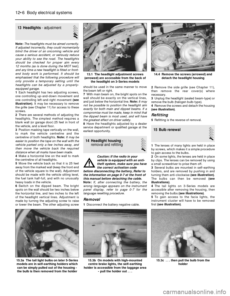
one controlling left-and-right movement (see
illustration). It may be necessary to remove
the grille (see Chapter 11) for access to these
screws.
2There are several methods of adjusting the
headlights. The simplest method requires a
blank wall (or garage door) 25 feet in front of
the vehicle, and a level floor.
3Position masking tape vertically on the wall,
to mark the vehicle centreline and the
centreline of both headlights. Note:It may be
easier to position the tape on the wall with the
vehicle parked only a few inches away, and
then move the vehicle back the required
distance when all marks have been made.
4Make a horizontal line on the wall to mark
the centreline of all headlights.
5Move the vehicle back so that it is 25 feet
away from the marked wall (keep the front end
of the vehicle square to the wall). Adjustment
should be made with the vehicle sitting level,
the fuel tank half-full, and with no unusually
heavy loads in the vehicle.
6Switch on the dipped beam. The bright
spots on the wall should be two inches below
the horizontal line, and two inches to the left
of the headlight vertical lines. Adjustment is
made by turning the adjusting screw to raise
or lower the beam. The other adjusting screwshould be used in the same manner to move
the beam left or right.
7With main beam on, the bright spots on the
wall should be exactly on the vertical lines,
and just below the horizontal line. Note:It may
not be possible to position the headlight aim
exactly for both main and dipped beams. If a
compromise must be made, keep in mind that
the dipped beam is most used, and will have
the greatest effect on driver safety.
8Have the headlights adjusted by a dealer
service department or qualified garage at the
earliest opportunity.
14 Headlight housing-
removal and refitting
1
Caution: If the radio in your
vehicle is equipped with an anti-
theft system, make sure you have
the correct activation code
before disconnecting the battery, Refer to
the information on page 0-7 at the front of
this manual before detaching the cable.
Note: If, after connecting the battery, the
wrong language appears on the instrument
panel display, refer to page 0-7 for the
language resetting procedure.
Removal
1Disconnect the battery negative cable.2Remove the side grille (see Chapter 11),
then remove the rear cover(s) where
necessary.
3Unplug the headlight (sealed beam-type) or
remove the bulb (halogen bulb-type).
4Remove the screws and detach the housing
(see illustration).
Refitting
5Refitting is the reverse of removal.
15 Bulb renewal
1
1The lenses of many lights are held in place
by screws, which makes it a simple procedure
to gain access to the bulbs.
2On some lights, the lenses are held in place
by clips. The lenses can be removed by using
a small screwdriver to prise them off.
3Several bulbs are mounted in self-earthing
holders, and are removed by pushing in and
turning them anti-clockwise (see illustration).
The bulbs can then be removed (see
illustrations).
4The tail lights on 3-Series models are
accessible after removing the housing, then
removing the bulbs (see illustrations).
5To gain access to the facia lights, the
instrument cluster will have to be removed
first (see illustration).
12•6 Body electrical systems
15.3c . . . then pull the bulb from the
holder15.3b On models with high-mounted
centre brake lights, the self-earthing
holder is accessible from the luggage area
- pull the holder out . . .15.3a The tail light bulbs on later 5-Series
models are in self-earthing holders which
can be simply pulled out of the housing -
the bulb is then removed from the holder
14.4 Remove the screws (arrowed) and
detach the headlight housing13.1 The headlight adjustment screws
(arrowed) are accessible from the back of
the headlight on 3-Series models
Page 177 of 228
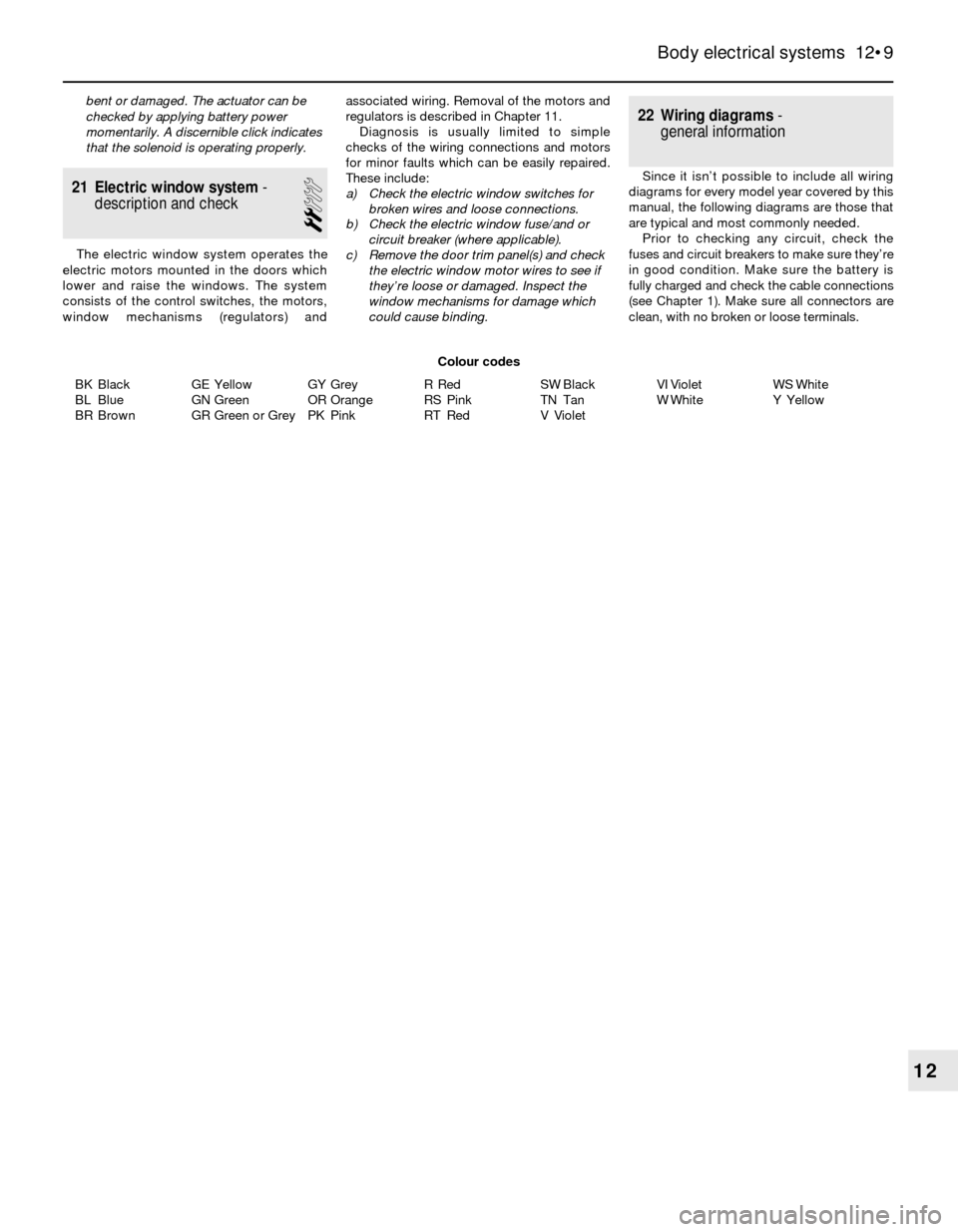
BK Black
BL Blue
BR BrownGE Yellow
GN Green
GR Green or GreyGY Grey
OR Orange
PK PinkR Red
RS Pink
RT RedSW Black
TN Tan
V VioletVI Violet
W WhiteWS White
Y Yellow
Body electrical systems 12•9
12
Colour codes bent or damaged. The actuator can be
checked by applying battery power
momentarily. A discernible click indicates
that the solenoid is operating properly.
21 Electric window system-
description and check
2
The electric window system operates the
electric motors mounted in the doors which
lower and raise the windows. The system
consists of the control switches, the motors,
window mechanisms (regulators) andassociated wiring. Removal of the motors and
regulators is described in Chapter 11.
Diagnosis is usually limited to simple
checks of the wiring connections and motors
for minor faults which can be easily repaired.
These include:
a) Check the electric window switches for
broken wires and loose connections.
b) Check the electric window fuse/and or
circuit breaker (where applicable).
c) Remove the door trim panel(s) and check
the electric window motor wires to see if
they’re loose or damaged. Inspect the
window mechanisms for damage which
could cause binding.
22 Wiring diagrams-
general information
Since it isn’t possible to include all wiring
diagrams for every model year covered by this
manual, the following diagrams are those that
are typical and most commonly needed.
Prior to checking any circuit, check the
fuses and circuit breakers to make sure they’re
in good condition. Make sure the battery is
fully charged and check the cable connections
(see Chapter 1). Make sure all connectors are
clean, with no broken or loose terminals.
Page 211 of 228
REF•10Fault Finding
Engine will not rotate when attempting to start
m mBattery terminal connections loose or corroded (Chapter 1).
m mBattery discharged or faulty (Chapter 1).
m mAutomatic transmission not completely engaged in Park (Chap-
ter 7B) or (on models with a clutch switch) clutch not completely
depressed (Chapter 8).
m mBroken, loose or disconnected wiring in the starting circuit
(Chapters 5 and 12).
m mStarter motor pinion jammed in flywheel ring gear (Chapter 5).
m mStarter solenoid faulty (Chapter 5).
m mStarter motor faulty (Chapter 5).
m mIgnition switch faulty (Chapter 12).
m mStarter pinion or flywheel teeth worn or broken (Chapter 5).
m mEngine internal problem (Chapter 2B).
Engine rotates, but will not start
m
mFuel tank empty.
m mBattery discharged (engine rotates slowly) (Chapter 5).
m mBattery terminal connections loose or corroded (Chapter 1).
m mLeaking fuel injector(s), faulty fuel pump, pressure regulator, etc
(Chapter 4).
m mFuel not reaching fuel injection system or carburettor (Chapter 4).
m mIgnition components damp or damaged (Chapter 5).
m mFuel injector stuck open (Chapter 4).
m mWorn, faulty or incorrectly-gapped spark plugs (Chapter 1).
m mBroken, loose or disconnected wiring in the starting circuit
(Chapter 5).
m mLoose distributor mounting bolts causing ignition timing to wander
(Chapters 1 and 5).
m mBroken, loose or disconnected wires at the ignition coil, or faulty
coil (Chapter 5).
Engine hard to start when cold
m mBattery discharged (Chapter 1).
m mFuel system malfunctioning (Chapter 4).
m mInjector(s) leaking or carburettor automatic choke faulty (Chap-
ter 4).
m mDistributor rotor carbon-tracked (Chapter 5).
Engine hard to start when hot
m
mAir filter element clogged (Chapter 1).
m mFuel not reaching the fuel injection system or carburettor (Chap-
ter 4).
m mCorroded battery connections, especially earth (negative)
connection (Chapter 1).
Starter motor noisy or excessively-rough in
engagement
m mPinion or flywheel gear teeth worn or broken (Chapter 5).
m mStarter motor mounting bolts loose or missing (Chapter 5).
Engine starts, but stops immediately
m
mLoose or faulty electrical connections at distributor, coil or
alternator (Chapter 5).
m mInsufficient fuel reaching the fuel injector(s) or carburettor
(Chapters 1 and 4).
m mDamaged fuel injection system speed sensors (Chapter 5).
m mFaulty fuel injection relays (Chapter 5).
Oil puddle under engine
m
mOil sump gasket and/or sump drain plug seal leaking (Chapter 2).
m mOil pressure sender unit leaking (Chapter 2).
m mValve cover gaskets leaking (Chapter 2).
m mEngine oil seals leaking (Chapter 2).
Engine idles erratically
m
mVacuum leakage (Chapter 4).
m mAir filter element clogged (Chapter 1).
m mFuel pump not delivering sufficient fuel to the fuel injection system
or carburettor (Chapter 4).
m mLeaking head gasket (Chapter 2).
m mTiming belt/chain and/or sprockets worn (Chapter 2).
m mCamshaft lobes worn (Chapter 2).
m mFaulty charcoal canister, where fitted (Chapter 6). This Section provides an easy-reference guide to the more
common problems which may occur during the operation of your
vehicle. These problems and their possible causes are grouped under
headings denoting various components or systems, such as Engine,
Cooling system, etc. They also refer you to the Chapter and/or
Section which deals with the problem.
Remember that successful fault diagnosis is not a mysterious
black art practised only by professional mechanics. It is simply the
result of the right knowledge combined with an intelligent, systematic
approach to the problem. Always work by a process of elimination,
starting with the simplest solution and working through to the mostcomplex - and never overlook the obvious. Anyone can run the fuel
tank dry or leave the lights on overnight, so don’t assume that you are
exempt from such oversights.
Finally, always establish a clear idea of why a problem has
occurred, and take steps to ensure that it doesn’t happen again. If the
electrical system fails because of a poor connection, check all other
connections in the system to make sure that they don’t fail as well. If a
particular fuse continues to blow, find out why - don’t just renew one
fuse after another. Remember, failure of a small component can often
be indicative of potential failure or incorrect functioning of a more
important component or system.
Engine
Page 212 of 228
REF•11
REF
Fault Finding
Engine misses at idle speed
m mSpark plugs worn or incorrectly-gapped (Chapter 1).
m mFaulty spark plug HT leads (Chapter 1).
m mVacuum leaks (Chapter 1).
m mIncorrect ignition timing (Chapter 5).
m mUneven or low compression (Chapter 2).
m mFaulty charcoal canister, where fitted (Chapter 6).
Engine misses throughout driving speed range
m
mFuel filter clogged and/or impurities in the fuel system (Chapter 1).
m mLow fuel output at the injectors, or partially-blocked carburettor
jets (Chapter 4).
m mFaulty or incorrectly-gapped spark plugs (Chapter 1).
m mIncorrect ignition timing (Chapter 5).
m mCracked distributor cap, disconnected distributor HT leads, or
damaged distributor components (Chapter 1).
m mFaulty spark plug HT leads (Chapter 1).
m mFaulty emission system components (Chapter 6).
m mLow or uneven cylinder compression pressures (Chapter 2).
m mWeak or faulty ignition system (Chapter 5).
m mVacuum leak in fuel injection system, intake manifold or vacuum
hoses (Chapter 4).
Engine misfires on acceleration
m mSpark plugs fouled (Chapter 1).
m mFuel injection system or carburettor malfunctioning (Chapter 4).
m mFuel filter clogged (Chapters 1 and 4).
m mIncorrect ignition timing (Chapter 5).
m mIntake manifold air leak (Chapter 4).
Engine surges while holding accelerator steady
m
mIntake air leak (Chapter 4).
m mFuel pump faulty (Chapter 4).
m mLoose fuel injector harness connections (Chapters 4 and 6).
m mDefective ECU (Chapter 5).
Engine lacks power
m
mIncorrect ignition timing (Chapter 5).
m mExcessive play in distributor shaft (Chapter 5).
m mWorn rotor, distributor cap or HT leads (Chapters 1 and 5).
m mFaulty or incorrectly-gapped spark plugs (Chapter 1).
m mFuel injection system or carburettor malfunctioning (Chapter 4).
m mFaulty coil (Chapter 5).
m mBrakes binding (Chapter 1).
m mAutomatic transmission fluid level incorrect (Chapter 1).
m mClutch slipping (Chapter 8).
m mFuel filter clogged and/or impurities in the fuel system (Chapter 1).
m mEmission control system not functioning properly (Chapter 6).
m mLow or uneven cylinder compression pressures (Chapter 2).
Engine stalls
m
mIdle speed incorrect (Chapter 1).
m mFuel filter clogged and/or water and impurities in the fuel system
(Chapter 1).
m mDistributor components damp or damaged (Chapter 5).
m mFaulty emissions system components (Chapter 6).
m mFaulty or incorrectly-gapped spark plugs (Chapter 1).
m mFaulty spark plug HT leads (Chapter 1).
m mVacuum leak in the fuel injection system, intake manifold or
vacuum hoses (Chapter 4).
Engine backfires
m mEmissions system not functioning properly (Chapter 6).
m mIgnition timing incorrect (Chapter 5).
m mFaulty secondary ignition system (cracked spark plug insulator,
faulty plug HT leads, distributor cap and/or rotor) (Chapters 1 and 5).
m mFuel injection system or carburettor malfunctioning (Chapter 4).
m mVacuum leak at fuel injector(s), intake manifold or vacuum hoses
(Chapter 4).
m mValve clearances incorrect (Chapter 1), or valve(s) sticking or
damaged (Chapter 2).
Pinking or knocking engine sounds when
accelerating or driving uphill
m mIncorrect grade of fuel.
m mIgnition timing incorrect (Chapter 5).
m mFuel injection system or carburettor in need of adjustment (Chap-
ter 4).
m mDamaged spark plugs or HT leads, or incorrect type fitted (Chapter 1).
m mWorn or damaged distributor components (Chapter 5).
m mFaulty emission system (Chapter 6).
m mVacuum leak (Chapter 4).
Engine runs with oil pressure light on
Caution: Stop the engine immediately if the oil
pressure light comes on and establish the cause.
Running the engine while the oil pressure is low can
cause severe damage.
m mLow oil level (Chapter 1).
m mIdle speed too low (Chapter 1).
m mShort-circuit in wiring (Chapter 12).
m mFaulty oil pressure sender unit (Chapter 2).
m mWorn engine bearings and/or oil pump (Chapter 2).
Engine runs-on after switching off
m
mIdle speed too high (Chapter 1).
m mExcessive engine operating temperature (Chapter 3).
m mIncorrect fuel octane grade.
m mSpark plugs defective or incorrect grade (Chapter 1).
Engine electrical system
Battery will not hold charge
m
mAlternator drivebelt defective or not adjusted properly (Chapter 1).
m mElectrolyte level low (Chapter 1).
m mBattery terminals loose or corroded (Chapter 1).
m mAlternator not charging properly (Chapter 5).
m mLoose, broken or faulty wiring in the charging circuit (Chapter 5).
m mShort in vehicle wiring (Chapters 5 and 12).
m mInternally-defective battery (Chapters 1 and 5).
m mIgnition (no-charge) warning light bulb blown - on some early
models (Chapter 5)
Ignition (no-charge) warning light fails to go out
m mFaulty alternator or charging circuit (Chapter 5).
m mAlternator drivebelt defective or out of adjustment (Chapter 1).
m mAlternator voltage regulator inoperative (Chapter 5).
Ignition (no-charge) warning light fails to come on
when key is turned
m mWarning light bulb defective (Chapter 12).
m mFault in the printed circuit, wiring or bulbholder (Chapter 12).
Page 213 of 228
REF•12Fault Finding
Fuel system
Excessive fuel consumption
m mDirty or clogged air filter element (Chapter 1).
m mIgnition timing incorrect (Chapter 5).
m mEmissions system not functioning properly (Chapter 6).
m mFuel injection internal parts or carburettor jets excessively worn or
damaged (Chapter 4).
m mLow tyre pressure or incorrect tyre size (Chapter 1).
m mUnsympathetic driving style, or unfavourable conditions.
Fuel leakage and/or fuel odour
Warning: Don’t drive the vehicle if a fuel leak is
suspected. Leaking fuel in the engine compartment
could catch fire.
m mLeak in a fuel feed or vent line (Chapter 4).
m mTank overfilled.
m mFuel injector or carburettor parts excessively worn, or fuel system
gaskets leaking (Chapter 4).
Cooling system
Overheating
m mInsufficient coolant in system (Chapter 1).
m mWater pump drivebelt defective or out of adjustment (Chapter 1).
m mRadiator matrix blocked, or grille restricted (Chapter 3).
m mThermostat faulty (Chapter 3).
m mRadiator cap not maintaining proper pressure (Chapter 3).
m mIgnition timing incorrect (Chapter 5).
Overcooling
m
mFaulty thermostat (Chapter 3).
External coolant leakage
m
mDeteriorated/damaged hoses; loose clamps (Chapters 1 and 3).
m mWater pump seal defective (Chapters 1 and 3).
m mLeakage from radiator matrix, heater matrix or header tank
(Chapter 3).
m mRadiator/engine block drain plugs or water jacket core plugs
leaking (Chapters 2 and 3).
Internal coolant leakage
m mLeaking cylinder head gasket (Chapter 2).
m mCracked cylinder bore or cylinder head (Chapter 2).
Coolant loss
m
mToo much coolant in system (Chapter 1).
m mCoolant boiling away because of overheating (see above).
m mInternal or external leakage (see above).
m mFaulty radiator cap (Chapter 3).
Poor coolant circulation
m
mInoperative water pump (Chapter 3).
m mRestriction in cooling system (Chapters 1 and 3).
m mWater pump drivebelt defective/out of adjustment (Chapter 1).
m mThermostat sticking (Chapter 3).
Clutch
Pedal travels to floor - no pressure or very little
resistance
m mMaster or slave cylinder faulty (Chapter 8).
m mFluid line burst or leaking (Chapter 8).
m mConnections leaking (Chapter 8).
m mNo fluid in reservoir (Chapter 1).
m mIf fluid is present in master cylinder dust cover, master cylinder rear
seal has failed (Chapter 8).
m mBroken release bearing or fork (Chapter 8).
Fluid in area of master cylinder dust cover, and on
pedal
m mRear seal failure in master cylinder (Chapter 8).
Fluid on slave cylinder
m
mSlave cylinder plunger seal faulty (Chapter 8).
Pedal feels “spongy” when depressed
m
mAir in system (Chapter 8).
Unable to select gears
m
mFaulty transmission (Chapter 7).
m mFaulty clutch plate (Chapter 8).
m mFork and bearing not assembled properly (Chapter 8).
m mFaulty pressure plate (Chapter 8).
m mPressure plate-to-flywheel bolts loose (Chapter 8).
Clutch slips (engine speed increases with no
increase in vehicle speed)
m mClutch plate worn (Chapter 8).
m mClutch plate is oil-soaked by leaking rear main seal (Chapter 8).
m mWarped pressure plate or flywheel (Chapter 8).
m mWeak diaphragm spring (Chapter 8).
m mClutch plate overheated.
Grabbing (chattering) as clutch is engaged
m
mOil on clutch plate lining, burned or glazed facings (Chapter 8).
m mWorn or loose engine or transmission mountings (Chapters 2
and 7A).
m mWorn splines on clutch plate hub (Chapter 8).
m mWarped pressure plate or flywheel (Chapter 8).
Noise in clutch area
m
mFork improperly fitted (Chapter 8).
m mFaulty release bearing (Chapter 8).
Clutch pedal stays on floor
m
mFork binding in housing (Chapter 8).
m mBroken release bearing or fork (Chapter 8).
High pedal effort
m
mFork binding in housing (Chapter 8).
m mPressure plate faulty (Chapter 8).
m mIncorrect-size master or slave cylinder fitted (Chapter 8).
Page 214 of 228
REF•13
REF
Fault Finding
Automatic transmission
Note:Due to the complexity of the automatic transmission, it is
difficult for the home mechanic to properly diagnose and service this
unit. For problems other than the following, the vehicle should be
taken to a dealer or transmission specialist.
Fluid leakage
m mAutomatic transmission fluid is a deep red colour. Fluid leaks
should not be confused with engine oil, which can easily be blown
by airflow onto the transmission.
m mTo pinpoint a leak, first remove all built-up dirt and grime from the
transmission housing with degreasing agents and/or by steam-
cleaning. Then drive the vehicle at low speed, so airflow will not
blow the leak far from its source. Raise the vehicle and determine
where the leak is coming from. Common areas of leakage are:
a) Transmission sump (Chapters 1 and 7B)
b) Filler pipe (Chapter 7B)
c) Transmission fluid cooler lines (Chapter 7B)
d) Speedometer sensor (Chapter 7B)
Transmission fluid brown, or has a burned smell
m mTransmission fluid burned; fluid should be changed. May indicate
transmission internal fault (Chapters 1 and 7B).
Transmission will not kickdown with accelerator
pedal pressed to the floor
m mKickdown cable out of adjustment (Chapter 7B).
General shift mechanism problems
m
mChapter 7B deals with checking and adjusting the shift linkage on
automatic transmissions. Common problems which may be
attributed to poorly-adjusted linkage are:
a) Engine starting in gears other than Park or Neutral.
b) Indicator on selector lever pointing to a gear other than the one
actually being used.
c) Vehicle moves when in Park.
m mRefer to Chapter 7B for the shift linkage adjustment procedure.
Engine will start in gears other than Park or Neutral
m
mInhibitor switch malfunctioning (Chapter 7B).
Transmission slips, shifts roughly, is noisy, or has
no drive in forward or reverse gears
m mThere are many probable causes for the above problems, but the
home mechanic should be concerned with only one possibility -
fluid level. Before taking the vehicle to an automatic transmission
specialist, check the level and condition of the fluid as described in
Chapter 1. Correct the fluid level as necessary, or change the fluid
if needed. If the problem persists, have a professional diagnose the
probable cause.
Manual transmission
Vibration
m mDamaged propeller shaft (Chapter 8).
m mOut-of-round tyres (Chapter 1).
m mTyre out-of-balance (Chapters 1 and 10).
m mWorn propeller shaft universal joint (Chapter 8).
Noisy in neutral with engine running
m
mWorn clutch release bearing (Chapter 8).
m mWorn transmission input shaft bearing (Chapter 7A).
Noisy in one particular gear
m
mDamaged or worn constant-mesh gears.
m mDamaged or worn synchronisers.
Noisy in all gears
m
mInsufficient lubricant (Chapter 1).
m mDamaged or worn bearings.
m mWorn or damaged input gear shaft and/or output gear shaft.
Slips out of gear
m
mWorn or incorrectly-adjusted linkage (Chapter 7A).
m mTransmission-to-engine mounting bolts loose (Chapter 7A).
m mShift linkage binding (Chapter 7A).
m mWorn shift fork (Chapter 7A).
Leaks lubricant
m
mExcessive amount of lubricant in transmission (Chapters 1 and 7A).
m mLoose or broken input shaft bearing retainer (Chapter 7A).
m mInput shaft bearing retainer O-ring and/or lip seal damaged
(Chapter 7A).
Page 215 of 228
REF•14Fault Finding
Brakes
Note:Before assuming that a brake problem exists, make sure that:
a) The tyres are in good condition and properly inflated (Chapter 1).
b) The wheel alignment (tracking) is correct (Chapter 10).
c) The vehicle is not loaded with weight in an unequal manner.
Vehicle pulls to one side during braking
m mIncorrect tyre pressures (Chapter 1).
m mWheel alignment (tracking) incorrect (Chapter 10)
m mUnmatched tyres on same axle.
m mRestricted brake lines or hoses (Chapter 9).
m mMalfunctioning caliper assembly (Chapter 9).
m mLoose suspension parts (Chapter 10).
m mLoose calipers (Chapter 9).
Noise (high-pitched squeal) when the brakes are
applied
m mFront and/or rear disc brake pads worn out. The noise comes from
the wear sensor rubbing against the disc. Renew the pads
immediately (Chapter 9).
Brake vibration (pedal pulsates)
Note:If the vehicle has ABS, it is normal for the brake pedal to pulsate
when the system is working.
m mExcessive lateral disc run-out (Chapter 9).
m mParallelism not within specifications (Chapter 9).
m mUneven pad wear - caused by caliper not sliding, due to improper
clearance or dirt (Chapter 9).
m mDefective disc (Chapter 9).
Excessive brake pedal travel
m
mPartial brake system failure (Chapter 9).
m mInsufficient fluid in master cylinder (Chapters 1 and 9).
m mAir trapped in system (Chapters 1 and 9).
Excessive pedal effort required to stop vehicle
m
mMalfunctioning brake servo unit (Chapter 9).
m mPartial system failure (Chapter 9).
m mExcessively-worn pads or shoes (Chapter 9).
m mCaliper piston stuck or sluggish (Chapter 9).
m mBrake pads contaminated with oil or grease (Chapter 9).
m mNew pads fitted and not yet seated. It will take a while for the new
material to seat against the disc.
Dragging brakes
m mMaster cylinder pistons not returning correctly (Chapter 9).
m mRestricted brakes lines or hoses (Chapters 1 and 9).
m mIncorrect handbrake adjustment (Chapter 9).
m mRear drum brake self-adjuster mechanism faulty (when applicable)
(Chapter 9).
Grabbing or uneven braking action
m mMalfunction of brake servo unit (Chapter 9).
m mBinding brake pedal mechanism (Chapter 9).
Brake pedal feels “spongy” when depressed
m
mAir in hydraulic lines (Chapter 9).
m mMaster cylinder mounting bolts loose (Chapter 9).
m mMaster cylinder defective (Chapter 9).
Brake pedal travels to the floor with little resistance
m
mLittle or no fluid in the master cylinder reservoir, caused by leaking
caliper piston(s), loose, damaged or disconnected brake lines
(Chapter 9).
Handbrake does not hold
m mHandbrake linkage incorrectly adjusted (Chapter 9).
m mHandbrake shoe linings worn out or contaminated (Chapter 9).