body BMW 3 SERIES 1984 E30 Owner's Guide
[x] Cancel search | Manufacturer: BMW, Model Year: 1984, Model line: 3 SERIES, Model: BMW 3 SERIES 1984 E30Pages: 228, PDF Size: 7.04 MB
Page 122 of 228
when the transmission selector lever is in Park
or Neutral.
Always detach the battery negative cable
before working on the starting system.
19 Starter motor-
in-vehicle check
2
Note:Before diagnosing starter problems,
make sure the battery is fully charged.
1If the starter motor does not turn at all when
the switch is operated, make sure that the
gear lever is in Neutral or Park (automatic
transmission) or, where applicable, that the
clutch pedal is depressed (manual
transmission).
2Make sure that the battery is charged, and
that all cables, both at the battery and starter
solenoid terminals, are clean and secure.
3If the starter motor spins but the engine is
not cranking, the overrun clutch in the starter
motor is slipping, and the starter motor must
be renewed.
4If, when the switch is actuated, the starter
motor does not operate at all but the solenoid
clicks, then the problem lies either in the
battery, the main solenoid contacts, or the
starter motor itself (or the engine is seized).
5If the solenoid plunger cannot be heard
when the switch is actuated, the battery is
faulty, the switch is defective, the fusible link
is burned-out (the circuit is open), or the
solenoid itself is defective.
6To check the solenoid, connect a jumper
lead between the battery (+) and the ignition
switch wire terminal (the small terminal) on the
solenoid. If the starter motor now operates,
the solenoid is OK and the problem is in the
ignition switch, starter inhibitor switch
(automatic transmission models), clutch
switch (some manual transmission models), or
the wiring.
7If the starter motor still does not operate,
remove the starter/solenoid assembly for
dismantling, testing and repair.
8If the starter motor cranks the engine at an
abnormally-slow speed, first make sure that
the battery is charged, and that all terminal
connections are tight. If the engine is partially-
seized, or has the wrong viscosity oil in it, it
will crank slowly.
9Run the engine until normal operating
temperature is reached, then disconnect the
coil HT lead from the distributor cap and earth
it on the engine.
10Connect a voltmeter positive lead to the
battery positive post, and connect the
negative lead to the negative post.11Crank the engine, and take the voltmeter
readings as soon as a steady figure is
indicated. Do not allow the starter motor to
turn for more than 10 seconds at a time. A
reading of 9 volts or more, with the starter
motor turning at normal cranking speed, is
normal. If the reading is 9 volts or more but
the cranking speed is slow, the solenoid
contacts are burned, there is a bad
connection, or the starter motor itself is faulty.
If the reading is less than 9 volts and the
cranking speed is slow, the starter motor is
faulty or the battery is responsible (defective
or discharged).
20 Starter motor-
removal and refitting
1
Note:If the starter motor is defective, it should
be renewed, or taken to an auto electrical
specialist for repair. Overhaul of the starter
motor is unlikely to be a practical proposition
for the home mechanic, even if spare parts are
available. However, the solenoid can be
renewed separately (see Section 21).
Removal
Caution: If the radio in your
vehicle is equipped with an anti-
theft system, make sure you
have the correct activation code
before disconnecting the battery. Refer to
the information on page 0-7 at the front of
this manual before detaching the cable.
Note: If, after connecting the battery, the
wrong language appears on the instrument
panel display, refer to page 0-7 for the
language resetting procedure.
1Detach the battery negative cable.
2Raise the vehicle and support it securely on
axle stands.
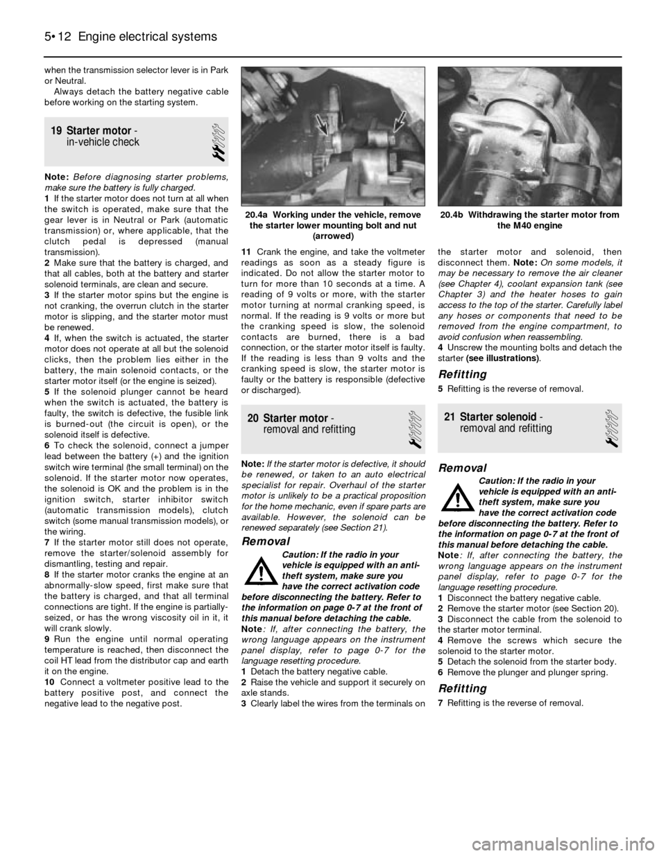
3Clearly label the wires from the terminals onthe starter motor and solenoid, then
disconnect them. Note: On some models, it
may be necessary to remove the air cleaner
(see Chapter 4), coolant expansion tank (see
Chapter 3) and the heater hoses to gain
access to the top of the starter. Carefully label
any hoses or components that need to be
removed from the engine compartment, to
avoid confusion when reassembling.
4Unscrew the mounting bolts and detach the
starter (see illustrations).
Refitting
5Refitting is the reverse of removal.
21 Starter solenoid-
removal and refitting
1
Removal
Caution: If the radio in your
vehicle is equipped with an anti-
theft system, make sure you
have the correct activation code
before disconnecting the battery. Refer to
the information on page 0-7 at the front of
this manual before detaching the cable.
Note: If, after connecting the battery, the
wrong language appears on the instrument
panel display, refer to page 0-7 for the
language resetting procedure.
1Disconnect the battery negative cable.
2Remove the starter motor (see Section 20).
3Disconnect the cable from the solenoid to
the starter motor terminal.
4Remove the screws which secure the
solenoid to the starter motor.
5Detach the solenoid from the starter body.
6Remove the plunger and plunger spring.
Refitting
7Refitting is the reverse of removal.
5•12 Engine electrical systems
20.4b Withdrawing the starter motor from
the M40 engine20.4a Working under the vehicle, remove
the starter lower mounting bolt and nut
(arrowed)
Page 125 of 228
Check
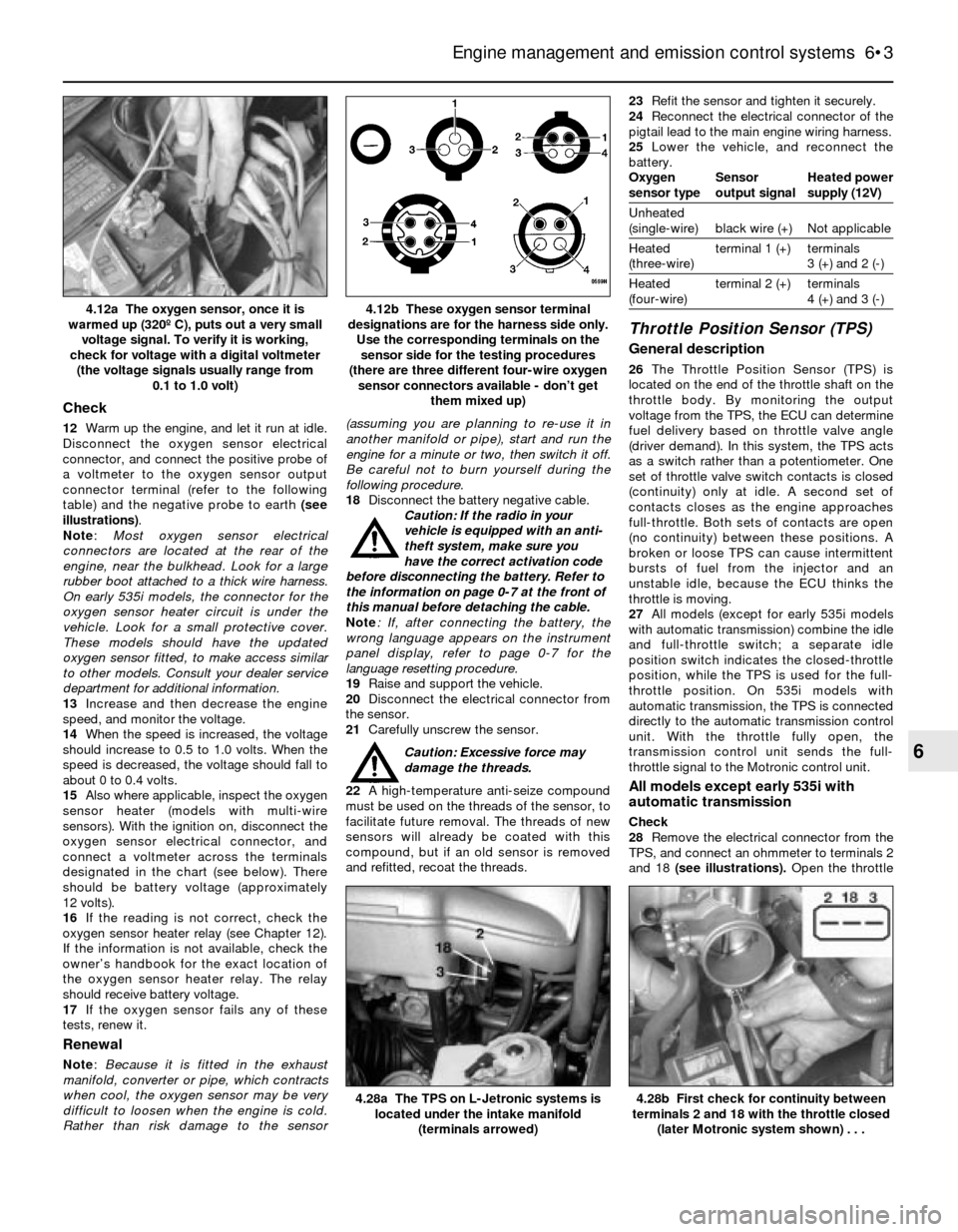
12Warm up the engine, and let it run at idle.
Disconnect the oxygen sensor electrical
connector, and connect the positive probe of
a voltmeter to the oxygen sensor output
connector terminal (refer to the following
table) and the negative probe to earth (see
illustrations).
Note:Most oxygen sensor electrical
connectors are located at the rear of the
engine, near the bulkhead. Look for a large
rubber boot attached to a thick wire harness.
On early 535i models, the connector for the
oxygen sensor heater circuit is under the
vehicle. Look for a small protective cover.
These models should have the updated
oxygen sensor fitted, to make access similar
to other models. Consult your dealer service
department for additional information.
13Increase and then decrease the engine
speed, and monitor the voltage.
14When the speed is increased, the voltage
should increase to 0.5 to 1.0 volts. When the
speed is decreased, the voltage should fall to
about 0 to 0.4 volts.
15Also where applicable, inspect the oxygen
sensor heater (models with multi-wire
sensors). With the ignition on, disconnect the
oxygen sensor electrical connector, and
connect a voltmeter across the terminals
designated in the chart (see below). There
should be battery voltage (approximately
12 volts).
16If the reading is not correct, check the
oxygen sensor heater relay (see Chapter 12).
If the information is not available, check the
owner’s handbook for the exact location of
the oxygen sensor heater relay. The relay
should receive battery voltage.
17If the oxygen sensor fails any of these
tests, renew it.
Renewal
Note: Because it is fitted in the exhaust
manifold, converter or pipe, which contracts
when cool, the oxygen sensor may be very
difficult to loosen when the engine is cold.
Rather than risk damage to the sensor(assuming you are planning to re-use it in
another manifold or pipe), start and run the
engine for a minute or two, then switch it off.
Be careful not to burn yourself during the
following procedure.
18Disconnect the battery negative cable.
Caution: If the radio in your
vehicle is equipped with an anti-
theft system, make sure you
have the correct activation code
before disconnecting the battery. Refer to
the information on page 0-7 at the front of
this manual before detaching the cable.
Note: If, after connecting the battery, the
wrong language appears on the instrument
panel display, refer to page 0-7 for the
language resetting procedure.
19Raise and support the vehicle.
20Disconnect the electrical connector from
the sensor.
21Carefully unscrew the sensor.
Caution: Excessive force may
damage the threads.
22A high-temperature anti-seize compound
must be used on the threads of the sensor, to
facilitate future removal. The threads of new
sensors will already be coated with this
compound, but if an old sensor is removed
and refitted, recoat the threads.23Refit the sensor and tighten it securely.
24Reconnect the electrical connector of the
pigtail lead to the main engine wiring harness.
25Lower the vehicle, and reconnect the
battery.
Oxygen Sensor Heated power
sensor type output signal supply (12V)
Unheated
(single-wire) black wire (+) Not applicable
Heated terminal 1 (+) terminals
(three-wire) 3 (+) and 2 (-)
Heated terminal 2 (+) terminals
(four-wire) 4 (+) and 3 (-)
Throttle Position Sensor (TPS)
General description
26The Throttle Position Sensor (TPS) is
located on the end of the throttle shaft on the
throttle body. By monitoring the output
voltage from the TPS, the ECU can determine
fuel delivery based on throttle valve angle
(driver demand). In this system, the TPS acts
as a switch rather than a potentiometer. One
set of throttle valve switch contacts is closed
(continuity) only at idle. A second set of
contacts closes as the engine approaches
full-throttle. Both sets of contacts are open
(no continuity) between these positions. A
broken or loose TPS can cause intermittent
bursts of fuel from the injector and an
unstable idle, because the ECU thinks the
throttle is moving.
27All models (except for early 535i models
with automatic transmission) combine the idle
and full-throttle switch; a separate idle
position switch indicates the closed-throttle
position, while the TPS is used for the full-
throttle position. On 535i models with
automatic transmission, the TPS is connected
directly to the automatic transmission control
unit. With the throttle fully open, the
transmission control unit sends the full-
throttle signal to the Motronic control unit.
All models except early 535i with
automatic transmission
Check
28Remove the electrical connector from the
TPS, and connect an ohmmeter to terminals 2
and 18 (see illustrations). Open the throttle
Engine management and emission control systems 6•3
4.12b These oxygen sensor terminal
designations are for the harness side only.
Use the corresponding terminals on the
sensor side for the testing procedures
(there are three different four-wire oxygen
sensor connectors available - don’t get
them mixed up)4.12a The oxygen sensor, once it is
warmed up (320º C), puts out a very small
voltage signal. To verify it is working,
check for voltage with a digital voltmeter
(the voltage signals usually range from
0.1 to 1.0 volt)
4.28b First check for continuity between
terminals 2 and 18 with the throttle closed
(later Motronic system shown) . . .4.28a The TPS on L-Jetronic systems is
located under the intake manifold
(terminals arrowed)
6
Page 127 of 228
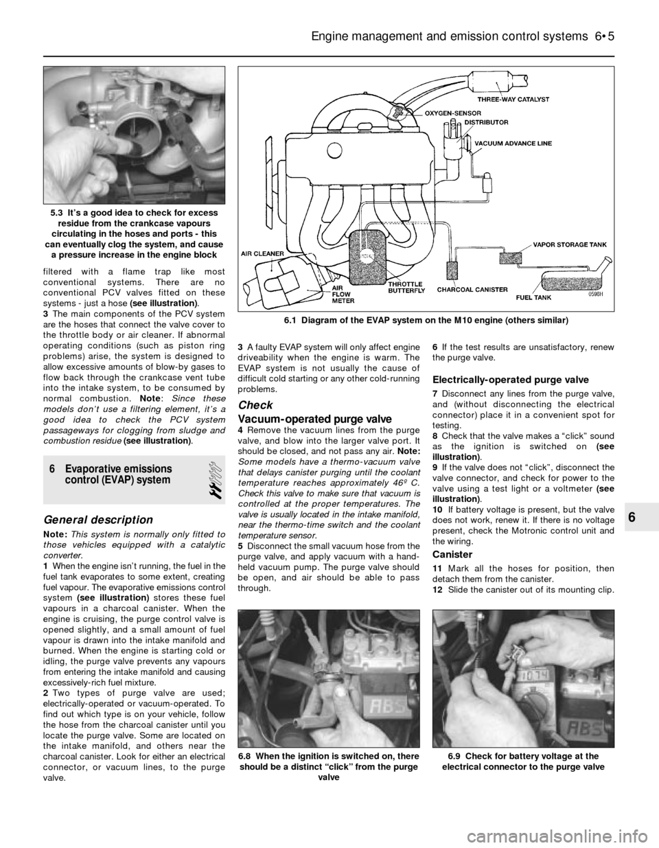
filtered with a flame trap like most
conventional systems. There are no
conventional PCV valves fitted on these
systems - just a hose (see illustration).
3The main components of the PCV system
are the hoses that connect the valve cover to
the throttle body or air cleaner. If abnormal
operating conditions (such as piston ring
problems) arise, the system is designed to
allow excessive amounts of blow-by gases to
flow back through the crankcase vent tube
into the intake system, to be consumed by
normal combustion. Note: Since these
models don’t use a filtering element, it’s a
good idea to check the PCV system
passageways for clogging from sludge and
combustion residue(see illustration).
6 Evaporative emissions
control (EVAP) system
2
General description
Note:This system is normally only fitted to
those vehicles equipped with a catalytic
converter.
1When the engine isn’t running, the fuel in the
fuel tank evaporates to some extent, creating
fuel vapour. The evaporative emissions control
system (see illustration)stores these fuel
vapours in a charcoal canister. When the
engine is cruising, the purge control valve is
opened slightly, and a small amount of fuel
vapour is drawn into the intake manifold and
burned. When the engine is starting cold or
idling, the purge valve prevents any vapours
from entering the intake manifold and causing
excessively-rich fuel mixture.
2Two types of purge valve are used;
electrically-operated or vacuum-operated. To
find out which type is on your vehicle, follow
the hose from the charcoal canister until you
locate the purge valve. Some are located on
the intake manifold, and others near the
charcoal canister. Look for either an electrical
connector, or vacuum lines, to the purge
valve.3A faulty EVAP system will only affect engine
driveability when the engine is warm. The
EVAP system is not usually the cause of
difficult cold starting or any other cold-running
problems.
Check
Vacuum-operated purge valve
4Remove the vacuum lines from the purge
valve, and blow into the larger valve port. It
should be closed, and not pass any air. Note:
Some models have a thermo-vacuum valve
that delays canister purging until the coolant
temperature reaches approximately 46º C.
Check this valve to make sure that vacuum is
controlled at the proper temperatures. The
valve is usually located in the intake manifold,
near the thermo-time switch and the coolant
temperature sensor.
5Disconnect the small vacuum hose from the
purge valve, and apply vacuum with a hand-
held vacuum pump. The purge valve should
be open, and air should be able to pass
through.6If the test results are unsatisfactory, renew
the purge valve.
Electrically-operated purge valve
7Disconnect any lines from the purge valve,
and (without disconnecting the electrical
connector) place it in a convenient spot for
testing.
8Check that the valve makes a “click” sound
as the ignition is switched on (see
illustration).
9If the valve does not “click”, disconnect the
valve connector, and check for power to the
valve using a test light or a voltmeter (see
illustration).
10If battery voltage is present, but the valve
does not work, renew it. If there is no voltage
present, check the Motronic control unit and
the wiring.
Canister
11Mark all the hoses for position, then
detach them from the canister.
12Slide the canister out of its mounting clip.
Engine management and emission control systems 6•5
6.1 Diagram of the EVAP system on the M10 engine (others similar)
6.9 Check for battery voltage at the
electrical connector to the purge valve6.8 When the ignition is switched on, there
should be a distinct “click” from the purge
valve
6
5.3 It’s a good idea to check for excess
residue from the crankcase vapours
circulating in the hoses and ports - this
can eventually clog the system, and cause
a pressure increase in the engine block
Page 128 of 228
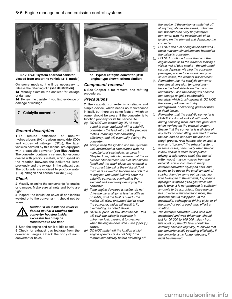
On some models, it will be necessary to
release the retaining clip (see illustration).
13Visually examine the canister for leakage
or damage.
14Renew the canister if you find evidence of
damage or leakage.
7 Catalytic converter
1
General description
1To reduce emissions of unburnt
hydrocarbons (HC), carbon monoxide (CO)
and oxides of nitrogen (NOx), the later
vehicles covered by this manual are equipped
with a catalytic converter (see illustration).
The converter contains a ceramic honeycomb
coated with precious metals, which speed up
the reaction between the pollutants listed
previously and the oxygen in the exhaust gas.
The pollutants are oxidised to produce water
(H
2O), nitrogen and carbon dioxide (CO2).
Check
2Visually examine the converter(s) for cracks
or damage. Make sure all nuts and bolts are
tight.
3Inspect the insulation cover (if applicable)
welded onto the converter - it should not be
loose.
Caution: If an insulation cover is
dented so that it touches the
converter housing inside,
excessive heat may be
transferred to the floor.
4Start the engine and run it at idle speed.
5Check for exhaust gas leakage from the
converter flanges. Check the body of each
converter for holes.
Component renewal
6See Chapter 4 for removal and refitting
procedures.
Precautions
7The catalytic converter is a reliable and
simple device, which needs no maintenance
in itself, but there are some facts of which an
owner should be aware, if the converter is to
function properly for its full service life.
(a) DO NOT use leaded (eg UK “4-star”)
petrol in a car equipped with a catalytic
converter - the lead will coat the precious
metals, reducing their converting
efficiency, and will eventually destroy the
converter.
(b) Always keep the ignition and fuel systems
well-maintained in accordance with the
manufacturer’s schedule, as given in
Chapter 1. In particular, ensure that the air
cleaner filter element, the fuel filter (where
fitted) and the spark plugs are renewed at
the correct interval. If the intake air/fuel
mixture is allowed to become too rich due
to neglect, unburned fuel will enter the
catalytic converter, overheating the
element and eventually destroying the
converter.
(c) If the engine develops a misfire, do not
drive the car at all (or at least as little as
possible) until the fault is cured - the
misfire will allow unburned fuel to enter
the converter, which will result in its
overheating, as noted above.
(d) DO NOT push- or tow-start the car - this
will soak the catalytic converter in
unburned fuel, causing it to overheat
when the engine does start - see (b) or (c)
above.
(e) DO NOT switch off the ignition at high
engine speeds - ie do not “blip” the
throttle immediately before switching offthe engine. If the ignition is switched off
at anything above idle speed, unburned
fuel will enter the (very hot) catalytic
converter, with the possible risk of its
igniting on the element and damaging the
converter.
(f) DO NOT use fuel or engine oil additives -
these may contain substances harmful to
the catalytic converter.
(g) DO NOT continue to use the car if the
engine burns oil to the extent of leaving a
visible trail of blue smoke - the unburned
carbon deposits will clog the converter
passages, and reduce its efficiency; in
severe cases, the element will overheat.
(h) Remember that the catalytic converter
operates at very high temperatures -
hence the heat shields on the car’s
underbody - and the casing will become
hot enough to ignite combustible
materials which brush against it. DO NOT,
therefore, park the car in dry
undergrowth, or over long grass or piles
of dead leaves.
(i) Remember that the catalytic converter is
FRAGILE - do not strike it with tools
during servicing work, and take great care
when working on the exhaust system.
Ensure that the converter is well clear of
any jacks or other lifting gear used to raise
the car, and do not drive the car over
rough ground, road humps, etc, in such a
way as to “ground” the exhaust system.
(j) In some cases, particularly when the car
is new and/or is used for stop/start
driving, a sulphurous smell (like that of
rotten eggs) may be noticed from the
exhaust. This is common to many
catalytic converter-equipped cars, and
seems to be due to the small amount of
sulphur found in some petrols reacting
with hydrogen in the exhaust, to produce
hydrogen sulphide (H
2S) gas; while this
gas is toxic, it is not produced in sufficient
amounts to be a problem. Once the car
has covered a few thousand miles, the
problem should disappear - in the
meanwhile, a change of driving style, or of
the brand of petrol used, may effect a
solution.
(k) The catalytic converter, used on a well-
maintained and well-driven car, should
last for 50 000 to 100 000 miles - from
this point on, the CO level should be
carefully checked regularly, to ensure that
the converter is still operating efficiently. If
the converter is no longer effective, it
must be renewed.
6•6 Engine management and emission control systems
7.1 Typical catalytic converter (M10
engine type shown, others similar)6.12 EVAP system charcoal canister
viewed from under the vehicle (316i model)
Page 132 of 228
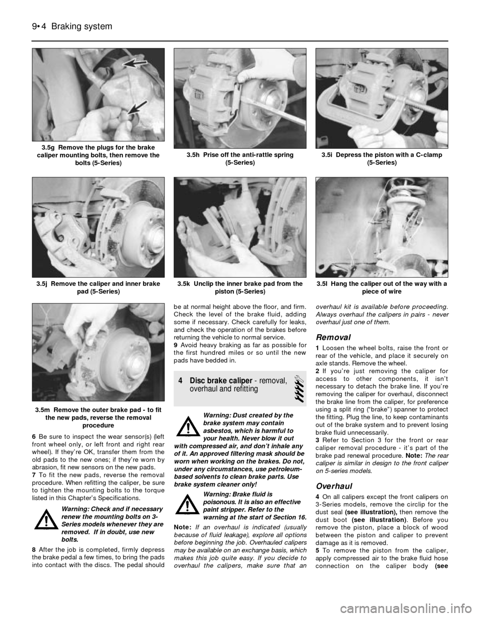
6Be sure to inspect the wear sensor(s) (left
front wheel only, or left front and right rear
wheel). If they’re OK, transfer them from the
old pads to the new ones; if they’re worn by
abrasion, fit new sensors on the new pads.
7To fit the new pads, reverse the removal
procedure. When refitting the caliper, be sure
to tighten the mounting bolts to the torque
listed in this Chapter’s Specifications.
Warning: Check and if necessary
renew the mounting bolts on 3-
Series models whenever they are
removed. If in doubt, use new
bolts.
8After the job is completed, firmly depress
the brake pedal a few times, to bring the pads
into contact with the discs. The pedal shouldbe at normal height above the floor, and firm.
Check the level of the brake fluid, adding
some if necessary. Check carefully for leaks,
and check the operation of the brakes before
returning the vehicle to normal service.
9Avoid heavy braking as far as possible for
the first hundred miles or so until the new
pads have bedded in.
4 Disc brake caliper- removal,
overhaul and refitting
4
Warning: Dust created by the
brake system may contain
asbestos, which is harmful to
your health. Never blow it out
with compressed air, and don’t inhale any
of it. An approved filtering mask should be
worn when working on the brakes. Do not,
under any circumstances, use petroleum-
based solvents to clean brake parts. Use
brake system cleaner only!
Warning: Brake fluid is
poisonous. It is also an effective
paint stripper. Refer to the
warning at the start of Section 16.
Note:If an overhaul is indicated (usually
because of fluid leakage), explore all options
before beginning the job. Overhauled calipers
may be available on an exchange basis, which
makes this job quite easy. If you decide to
overhaul the calipers, make sure that anoverhaul kit is available before proceeding.
Always overhaul the calipers in pairs - never
overhaul just one of them.
Removal
1Loosen the wheel bolts, raise the front or
rear of the vehicle, and place it securely on
axle stands. Remove the wheel.
2If you’re just removing the caliper for
access to other components, it isn’t
necessary to detach the brake line. If you’re
removing the caliper for overhaul, disconnect
the brake line from the caliper, for preference
using a split ring (“brake”) spanner to protect
the fitting. Plug the line, to keep contaminants
out of the brake system and to prevent losing
brake fluid unnecessarily.
3Refer to Section 3 for the front or rear
caliper removal procedure - it’s part of the
brake pad renewal procedure. Note:The rear
caliper is similar in design to the front caliper
on 5-series models.
Overhaul
4On all calipers except the front calipers on
3-Series models, remove the circlip for the
dust seal (see illustration),then remove the
dust boot (see illustration). Before you
remove the piston, place a block of wood
between the piston and caliper to prevent
damage as it is removed.
5To remove the piston from the caliper,
apply compressed air to the brake fluid hose
connection on the caliper body (see
9•4 Braking system
3.5l Hang the caliper out of the way with a
piece of wire
3.5m Remove the outer brake pad - to fit
the new pads, reverse the removal
procedure
3.5k Unclip the inner brake pad from the
piston (5-Series)3.5j Remove the caliper and inner brake
pad (5-Series)
3.5i Depress the piston with a C-clamp
(5-Series)3.5h Prise off the anti-rattle spring
(5-Series)3.5g Remove the plugs for the brake
caliper mounting bolts, then remove the
bolts (5-Series)
Page 137 of 228
friction surfaces of the brake shoes or
drums.
12Make sure the adjuster assembly is
properly engaged with its respective notch in
the handbrake lever.
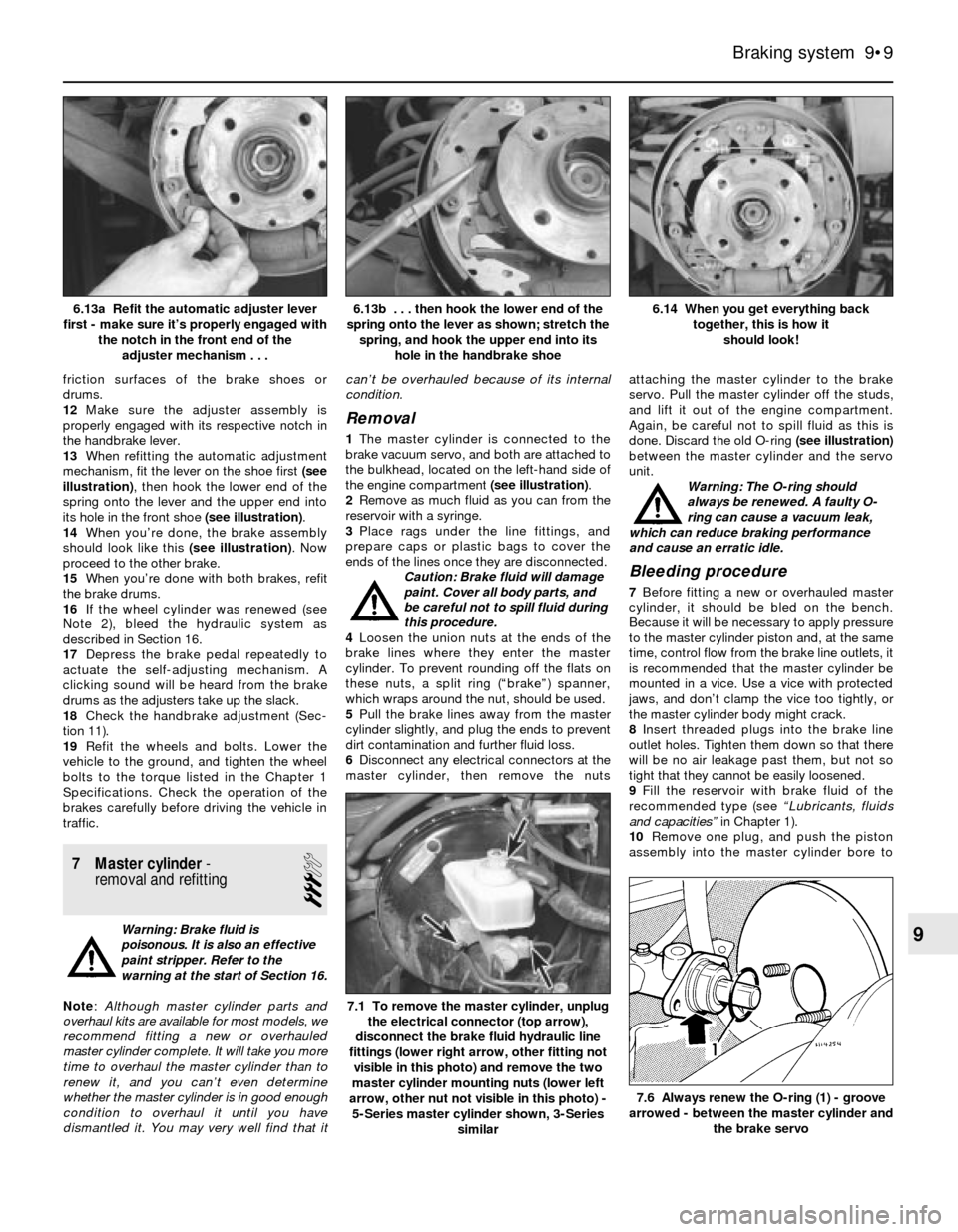
13When refitting the automatic adjustment
mechanism, fit the lever on the shoe first (see
illustration), then hook the lower end of the
spring onto the lever and the upper end into
its hole in the front shoe (see illustration).
14When you’re done, the brake assembly
should look like this (see illustration). Now
proceed to the other brake.
15When you’re done with both brakes, refit
the brake drums.
16If the wheel cylinder was renewed (see
Note 2), bleed the hydraulic system as
described in Section 16.
17Depress the brake pedal repeatedly to
actuate the self-adjusting mechanism. A
clicking sound will be heard from the brake
drums as the adjusters take up the slack.
18Check the handbrake adjustment (Sec-
tion 11).
19Refit the wheels and bolts. Lower the
vehicle to the ground, and tighten the wheel
bolts to the torque listed in the Chapter 1
Specifications. Check the operation of the
brakes carefully before driving the vehicle in
traffic.
7 Master cylinder-
removal and refitting
3
Warning: Brake fluid is
poisonous. It is also an effective
paint stripper. Refer to the
warning at the start of Section 16.
Note: Although master cylinder parts and
overhaul kits are available for most models, we
recommend fitting a new or overhauled
master cylinder complete. It will take you more
time to overhaul the master cylinder than to
renew it, and you can’t even determine
whether the master cylinder is in good enough
condition to overhaul it until you have
dismantled it. You may very well find that itcan’t be overhauled because of its internal
condition.
Removal
1The master cylinder is connected to the
brake vacuum servo, and both are attached to
the bulkhead, located on the left-hand side of
the engine compartment (see illustration).
2Remove as much fluid as you can from the
reservoir with a syringe.
3Place rags under the line fittings, and
prepare caps or plastic bags to cover the
ends of the lines once they are disconnected.
Caution: Brake fluid will damage
paint. Cover all body parts, and
be careful not to spill fluid during
this procedure.
4Loosen the union nuts at the ends of the
brake lines where they enter the master
cylinder. To prevent rounding off the flats on
these nuts, a split ring (“brake”) spanner,
which wraps around the nut, should be used.
5Pull the brake lines away from the master
cylinder slightly, and plug the ends to prevent
dirt contamination and further fluid loss.
6Disconnect any electrical connectors at the
master cylinder, then remove the nutsattaching the master cylinder to the brake
servo. Pull the master cylinder off the studs,
and lift it out of the engine compartment.
Again, be careful not to spill fluid as this is
done. Discard the old O-ring (see illustration)
between the master cylinder and the servo
unit.
Warning: The O-ring should
always be renewed. A faulty O-
ring can cause a vacuum leak,
which can reduce braking performance
and cause an erratic idle.
Bleeding procedure
7Before fitting a new or overhauled master
cylinder, it should be bled on the bench.
Because it will be necessary to apply pressure
to the master cylinder piston and, at the same
time, control flow from the brake line outlets, it
is recommended that the master cylinder be
mounted in a vice. Use a vice with protected
jaws, and don’t clamp the vice too tightly, or
the master cylinder body might crack.
8Insert threaded plugs into the brake line
outlet holes. Tighten them down so that there
will be no air leakage past them, but not so
tight that they cannot be easily loosened.
9Fill the reservoir with brake fluid of the
recommended type (see “Lubricants, fluids
and capacities” in Chapter 1).
10Remove one plug, and push the piston
assembly into the master cylinder bore to
Braking system 9•9
6.14 When you get everything back
together, this is how it
should look! 6.13b . . . then hook the lower end of the
spring onto the lever as shown; stretch the
spring, and hook the upper end into its
hole in the handbrake shoe6.13a Refit the automatic adjuster lever
first - make sure it’s properly engaged with
the notch in the front end of the
adjuster mechanism . . .
7.6 Always renew the O-ring (1) - groove
arrowed - between the master cylinder and
the brake servo
7.1 To remove the master cylinder, unplug
the electrical connector (top arrow),
disconnect the brake fluid hydraulic line
fittings (lower right arrow, other fitting not
visible in this photo) and remove the two
master cylinder mounting nuts (lower left
arrow, other nut not visible in this photo) -
5-Series master cylinder shown, 3-Series
similar
9
Page 144 of 228
Torque wrench settingsNm
Front suspension
Strut damper rod nut
Rod with external hexagon . . . . . . . . . . . . . . . . . . . . . . 65
Rod with internal hexagon . . . . . . . . . . . . . . . . . . . . . . 44
Strut cartridge threaded collar . . . . . . . . . . . . . . . . . . . . . . . 130
Strut upper mounting nuts . . . . . . . . . . . . . . . . . . . . . . . . . . 22
Front control arm (3-Series)
Control arm-to-steering knuckle balljoint nut . . . . . . . . . . 64
Control arm-to-subframe balljoint nut . . . . . . . . . . . . . . . 83
Control arm bush bracket bolts . . . . . . . . . . . . . . . . . . . . 41
Lower control arm (5-Series)
Control arm-to-steering arm balljoint stud nut . . . . . . . . . 85
Control arm pivot bolt . . . . . . . . . . . . . . . . . . . . . . . . . . . . 77
Thrust arm (5-Series)
Thrust arm-to-steering arm balljoint stud nut . . . . . . . . . . 85
Thrust arm through-bolt . . . . . . . . . . . . . . . . . . . . . . . . . . 130
Front hub (wheel bearing) nut . . . . . . . . . . . . . . . . . . . . . . . . 290
Steering arm-to-strut bolts (5-Series) . . . . . . . . . . . . . . . . . . 65
Anti-roll bar (3-Series)
Anti-roll bar-to-connecting link bolt . . . . . . . . . . . . . . . . . 41
Anti-roll bar mounting brackets-to-subframe . . . . . . . . . . 22
Connecting link-to-bracket . . . . . . . . . . . . . . . . . . . . . . . . 22
Connecting link bracket-to-control arm . . . . . . . . . . . . . . 41
Anti-roll bar (5-Series)
Anti-roll bar mounting brackets . . . . . . . . . . . . . . . . . . . . 22
Anti-roll bar link-to-strut housing locknut
Yellow chrome . . . . . . . . . . . . . . . . . . . . . . . . . . . . . . . 20
White chrome . . . . . . . . . . . . . . . . . . . . . . . . . . . . . . . . 33
Yellow . . . . . . . . . . . . . . . . . . . . . . . . . . . . . . . . . . . . . . 58
10•2 Suspension and steering systems
Torque wrench settingsNm
Rear suspension
Rear shock absorber (3-Series)
Shock absorber-to-upper mounting bracket . . . . . . . . . . 12 to 15
Shock absorber-to-trailing arm . . . . . . . . . . . . . . . . . . . . 71 to 85
Rear shock absorber (5-Series)
Lower mounting bolt . . . . . . . . . . . . . . . . . . . . . . . . . . . . . 125 to 142
Upper mounting nut . . . . . . . . . . . . . . . . . . . . . . . . . . . . . 22 to 24
Upper spring mounting-to-shock absorber locknut . . . . . 22 to 24
Trailing arms (3-Series)
Trailing arm-to-lower mounting . . . . . . . . . . . . . . . . . . . . 71 to 85
Trailing arm-to-anti-roll bar . . . . . . . . . . . . . . . . . . . . . . . . 22 to 23
Trailing arms (5-Series)
Trailing arm-to-rear axle carrier (rubber bush
through-bolt and nut) . . . . . . . . . . . . . . . . . . . . . . . . . . 66
Trailing arm-to-axle carrier connecting link (1983-on) . . . 126
Rear wheel bearing drive flange axle nut (5-Series)
M22 . . . . . . . . . . . . . . . . . . . . . . . . . . . . . . . . . . . . . . . . 175 to 210
M27 . . . . . . . . . . . . . . . . . . . . . . . . . . . . . . . . . . . . . . . . 235 to 260
Steering system
Steering wheel retaining nut . . . . . . . . . . . . . . . . . . . . . . . . . 79
Steering column universal joint pinch-bolt . . . . . . . . . . . . . . 22
Steering gear-to-subframe mounting bolts (3-Series) . . . . . 41
Steering box-to-front suspension subframe bolts (5-Series) 42
Track rod end-to-steering arm nut . . . . . . . . . . . . . . . . . . . . 37
Track rod end clamping bolt . . . . . . . . . . . . . . . . . . . . . . . . . 14
Pitman arm-to-steering box (5-Series) . . . . . . . . . . . . . . . . . 140
Steering linkage balljoints (all) . . . . . . . . . . . . . . . . . . . . . . . 37
1 General information
Warning: Whenever any of the
suspension or steering fasteners
are loosened or removed, they
must be inspected and if
necessary, new ones fitted, of the same
part number or of original-equipment
quality and design. Torque specifications
must be followed for proper reassembly
and component retention. Never attempt
to heat, straighten or weld any suspension
or steering component. Any bent or
damaged parts must be renewed.
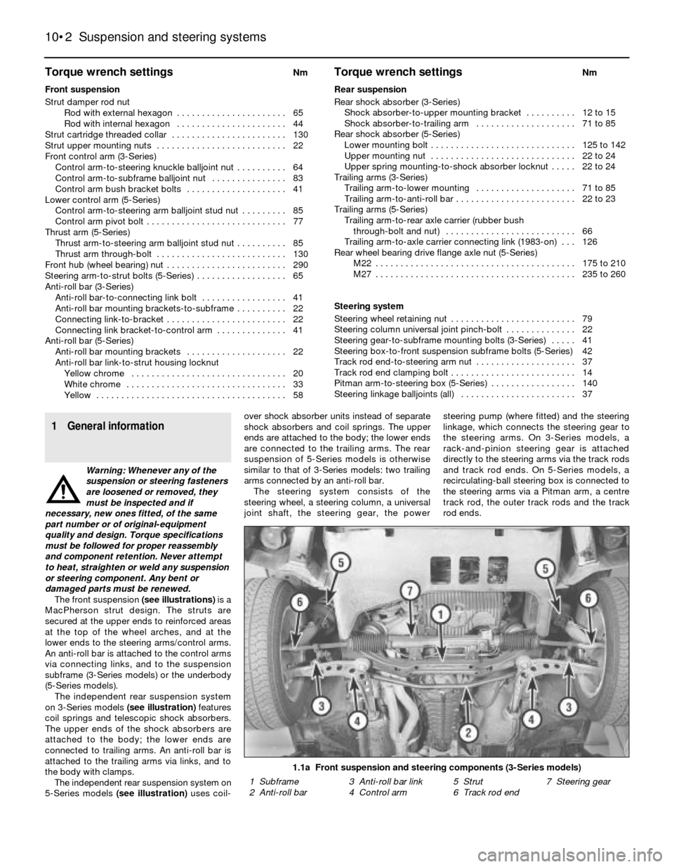
The front suspension (see illustrations)is a
MacPherson strut design. The struts are
secured at the upper ends to reinforced areas
at the top of the wheel arches, and at the
lower ends to the steering arms/control arms.
An anti-roll bar is attached to the control arms
via connecting links, and to the suspension
subframe (3-Series models) or the underbody
(5-Series models).
The independent rear suspension system
on 3-Series models (see illustration)features
coil springs and telescopic shock absorbers.
The upper ends of the shock absorbers are
attached to the body; the lower ends are
connected to trailing arms. An anti-roll bar is
attached to the trailing arms via links, and to
the body with clamps.
The independent rear suspension system on
5-Series models (see illustration)uses coil-over shock absorber units instead of separate
shock absorbers and coil springs. The upper
ends are attached to the body; the lower ends
are connected to the trailing arms. The rear
suspension of 5-Series models is otherwise
similar to that of 3-Series models: two trailing
arms connected by an anti-roll bar.
The steering system consists of the
steering wheel, a steering column, a universal
joint shaft, the steering gear, the powersteering pump (where fitted) and the steering
linkage, which connects the steering gear to
the steering arms. On 3-Series models, a
rack-and-pinion steering gear is attached
directly to the steering arms via the track rods
and track rod ends. On 5-Series models, a
recirculating-ball steering box is connected to
the steering arms via a Pitman arm, a centre
track rod, the outer track rods and the track
rod ends.
1.1a Front suspension and steering components (3-Series models)
1 Subframe 3 Anti-roll bar link 5 Strut 7 Steering gear
2 Anti-roll bar 4 Control arm 6 Track rod end
Page 146 of 228
2 Front anti-roll bar-
removal and refitting
2
Removal
1Raise the front of the vehicle, and support it
securely on axle stands.
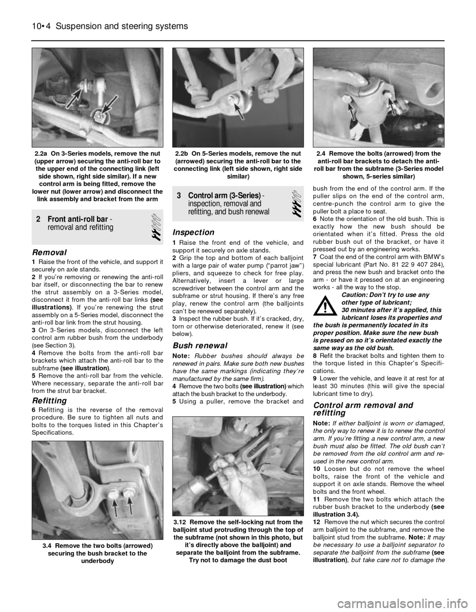
2If you’re removing or renewing the anti-roll
bar itself, or disconnecting the bar to renew
the strut assembly on a 3-Series model,
disconnect it from the anti-roll bar links (see
illustrations). If you’re renewing the strut
assembly on a 5-Series model, disconnect the
anti-roll bar link from the strut housing.
3On 3-Series models, disconnect the left
control arm rubber bush from the underbody
(see Section 3).
4Remove the bolts from the anti-roll bar
brackets which attach the anti-roll bar to the
subframe (see illustration).
5Remove the anti-roll bar from the vehicle.
Where necessary, separate the anti-roll bar
from the strut bar bracket.
Refitting
6Refitting is the reverse of the removal
procedure. Be sure to tighten all nuts and
bolts to the torques listed in this Chapter’s
Specifications.
3 Control arm (3-Series)-
inspection, removal and
refitting, and bush renewal
3
Inspection
1Raise the front end of the vehicle, and
support it securely on axle stands.
2Grip the top and bottom of each balljoint
with a large pair of water pump (“parrot jaw”)
pliers, and squeeze to check for free play.
Alternatively, insert a lever or large
screwdriver between the control arm and the
subframe or strut housing. If there’s any free
play, renew the control arm (the balljoints
can’t be renewed separately).
3Inspect the rubber bush. If it’s cracked, dry,
torn or otherwise deteriorated, renew it (see
below).
Bush renewal
Note:Rubber bushes should always be
renewed in pairs. Make sure both new bushes
have the same markings (indicating they’re
manufactured by the same firm).
4Remove the two bolts (see illustration)which
attach the bush bracket to the underbody.
5Using a puller, remove the bracket andbush from the end of the control arm. If the
puller slips on the end of the control arm,
centre-punch the control arm to give the
puller bolt a place to seat.
6Note the orientation of the old bush. This is
exactly how the new bush should be
orientated when it’s fitted. Press the old
rubber bush out of the bracket, or have it
pressed out by an engineering works.
7Coat the end of the control arm with BMW’s
special lubricant (Part No. 81 22 9 407 284),
and press the new bush and bracket onto the
arm - or have it pressed on at an engineering
works - all the way to the stop.
Caution: Don’t try to use any
other type of lubricant;
30 minutes after it’s applied, this
lubricant loses its properties and
the bush is permanently located in its
proper position. Make sure the new bush
is pressed on so it’s orientated exactly the
same way as the old bush.
8Refit the bracket bolts and tighten them to
the torque listed in this Chapter’s Specifi-
cations.
9Lower the vehicle, and leave it at rest for at
least 30 minutes (this will give the special
lubricant time to dry).
Control arm removal and
refitting
Note:If either balljoint is worn or damaged,
the only way to renew it is to renew the control
arm. If you’re fitting a new control arm, a new
bush must also be fitted. The old bush can’t
be removed from the old control arm and re-
used in the new control arm.
10Loosen but do not remove the wheel
bolts, raise the front of the vehicle and
support it on axle stands. Remove the wheel
bolts and the front wheel.
11Remove the two bolts which attach the
rubber bush bracket to the underbody (see
illustration 3.4).
12Remove the nut which secures the control
arm balljoint to the subframe, and remove the
balljoint stud from the subframe. Note:It may
be necessary to use a balljoint separator to
separate the balljoint from the subframe (see
illustration), but take care not to damage the
10•4 Suspension and steering systems
3.12 Remove the self-locking nut from the
balljoint stud protruding through the top of
the subframe (not shown in this photo, but
it’s directly above the balljoint) and
separate the balljoint from the subframe.
Try not to damage the dust boot
3.4 Remove the two bolts (arrowed)
securing the bush bracket to the
underbody
2.4 Remove the bolts (arrowed) from the
anti-roll bar brackets to detach the anti-
roll bar from the subframe (3-Series model
shown, 5-series similar)2.2b On 5-Series models, remove the nut
(arrowed) securing the anti-roll bar to the
connecting link (left side shown, right side
similar)2.2a On 3-Series models, remove the nut
(upper arrow) securing the anti-roll bar to
the upper end of the connecting link (left
side shown, right side similar). If a new
control arm is being fitted, remove the
lower nut (lower arrow) and disconnect the
link assembly and bracket from the arm
Page 151 of 228
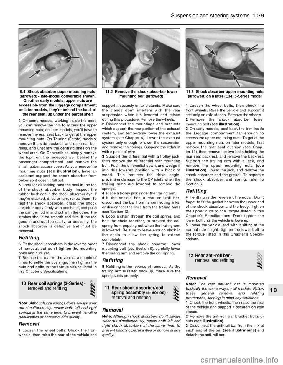
4On some models, working inside the boot,
you can remove the trim to access the upper
mounting nuts; on later models, you’ll have to
remove the rear seat back to get at the upper
mounting nuts. On Touring (Estate) models,
remove the side backrest and rear seat belt
reels, and unscrew the centring shell on the
wheel arch. On Convertibles, simply remove
the top from the recessed well behind the
passenger compartment, and remove the
small rubber access cover. As you remove the
mounting nuts (see illustration), have an
assistant support the shock absorber from
below so it doesn’t fall out.
5Look for oil leaking past the seal in the top
of the shock absorber body. Inspect the
rubber bushings in the shock absorber eye. If
they’re cracked, dried or torn, renew them. To
test the shock absorber, grasp the shock
absorber body firmly with one hand, and push
the damper rod in and out with the other. The
strokes should be smooth and firm. If the rod
goes in and out too easily, or unevenly, the
shock absorber is defective and must be
renewed.
Refitting
6Fit the shock absorbers in the reverse order
of removal, but don’t tighten the mounting
bolts and nuts yet.
7Bounce the rear of the vehicle a couple of
times to settle the bushings, then tighten the
nuts and bolts to the torque values listed in
this Chapter’s Specifications.
10 Rear coil springs (3-Series)-
removal and refitting
4
Note: Although coil springs don’t always wear
out simultaneously, renew both left and right
springs at the same time, to prevent handling
peculiarities or abnormal ride quality.
Removal
1Loosen the wheel bolts. Chock the front
wheels, then raise the rear of the vehicle andsupport it securely on axle stands. Make sure
the stands don’t interfere with the rear
suspension when it’s lowered and raised
during this procedure. Remove the wheels.
2Disconnect the mountings and brackets
which support the rear portion of the exhaust
system, and temporarily lower the exhaust
system (see Chapter 4). Lower the exhaust
system only enough to lower the suspension
and remove the springs. Suspend the exhaust
with a piece of wire.
3Support the differential with a trolley jack,
then remove the differential rear mounting
bolt. Push the differential down, and wedge it
into this lowered position with a block of
wood. This reduces the drive angle,
preventing damage to the CV joints when the
trailing arms are lowered to remove the
springs.
4Place a trolley jack under the trailing arm.
5If the vehicle has a rear anti-roll bar,
disconnect the bar from its connecting links,
or disconnect the links from the trailing arms
(see Section 12).
6Loop a chain through the coil spring, and
bolt the chain together, to prevent the coil
spring from popping out when the trailing arm
is lowered. Be sure to leave enough slack in
the chain to allow the spring to extend
completely.
7Disconnect the shock absorber lower
mounting bolt (see Section 9), carefully lower
the trailing arm and remove the coil spring.
Refitting
8Refitting is the reverse of removal. As the
trailing arm is raised back up, make sure the
spring seats properly.
11 Rear shock absorber/coil
spring assembly (5-Series)-
removal and refitting
4
Removal
Note:Although shock absorbers don’t always
wear out simultaneously, renew both left and
right shock absorbers at the same time, to
prevent handling peculiarities or abnormal ride
quality.1Loosen the wheel bolts, then chock the
front wheels. Raise the vehicle and support it
securely on axle stands. Remove the wheels.
2Remove the shock absorber lower
mounting bolt (see illustration).
3On early models, peel back the trim inside
the luggage compartment far enough to
access the upper mounting nuts. To get at the
upper mounting nuts on later models, first
remove the rear seat cushion (see Chap-
ter 11), then remove the two bolts holding the
rear seat backrest, and remove the backrest.
Support the trailing arm with a jack, and
remove the upper mounting nuts (see
illustration). Lower the jack, and remove the
shock absorber and the gasket. To separate
the shock absorber and spring, refer to
Section 6.
Refitting
4Refitting is the reverse of removal. Don’t
forget to fit the gasket between the upper end
of the shock absorber and the body. Tighten
the upper nuts to the torque listed in this
Chapter’s Specifications. Don’t tighten the
lower bolt until the vehicle is lowered.
5Lower the vehicle, and with it sitting at the
normal ride height, tighten the lower bolt to
the torque listed in this Chapter’s Specifi-
cations.
12 Rear anti-roll bar-
removal and refitting
2
Removal
Note:The rear anti-roll bar is mounted
basically the same way on all models. Follow
these general removal and refitting
procedures, keeping in mind any variations.
1Chock the front wheels, then raise the rear
of the vehicle and support it securely on axle
stands.
2Remove the anti-roll bar bracket bolts or
nuts (see illustration).
3Disconnect the anti-roll bar from the link at
each end of the bar (see illustrations)and
detach the anti-roll bar.
Suspension and steering systems 10•9
11.3 Shock absorber upper mounting nuts
(arrowed) on a later (E34) 5-Series model11.2 Remove the shock absorber lower
mounting bolt (arrowed)9.4 Shock absorber upper mounting nuts
(arrowed) - late-model convertible shown.
On other early models, upper nuts are
accessible from the luggage compartment;
on later models, they’re behind the back of
the rear seat, up under the parcel shelf
10
Page 157 of 228
21 Steering box (5-Series)-
removal and refitting
4
Removal
Note:If you find that the steering box is
defective, it is not recommended that you
overhaul it. Because of the special tools
needed to do the job, it is best to let your
dealer service department overhaul it for you
(otherwise, fit a new unit). Removal and
refitting the steering box is outlined here.
1On 5-Series E28 (“old-shape”) models,
discharge the hydraulic system by depressing
the brake pedal about 20 times.
2Using a large syringe or hand pump, empty
the power steering fluid reservoir (see Chap-
ter 1).
3Raise the front of the vehicle and support it
securely on axle stands.
4Support the front of the engine with a trolley
jack. Place a block of wood between the jack
head and the sump to protect the sump from
damage.
5Remove the pivot bolts from the inner ends
of the front control arms (see Section 4).
6Remove the nuts from the left and right
engine mountings (see Chapter 2).
7Remove the mounting bolts (two on each
side on earlier models, three on each side on
later models) from the subframe crossmember
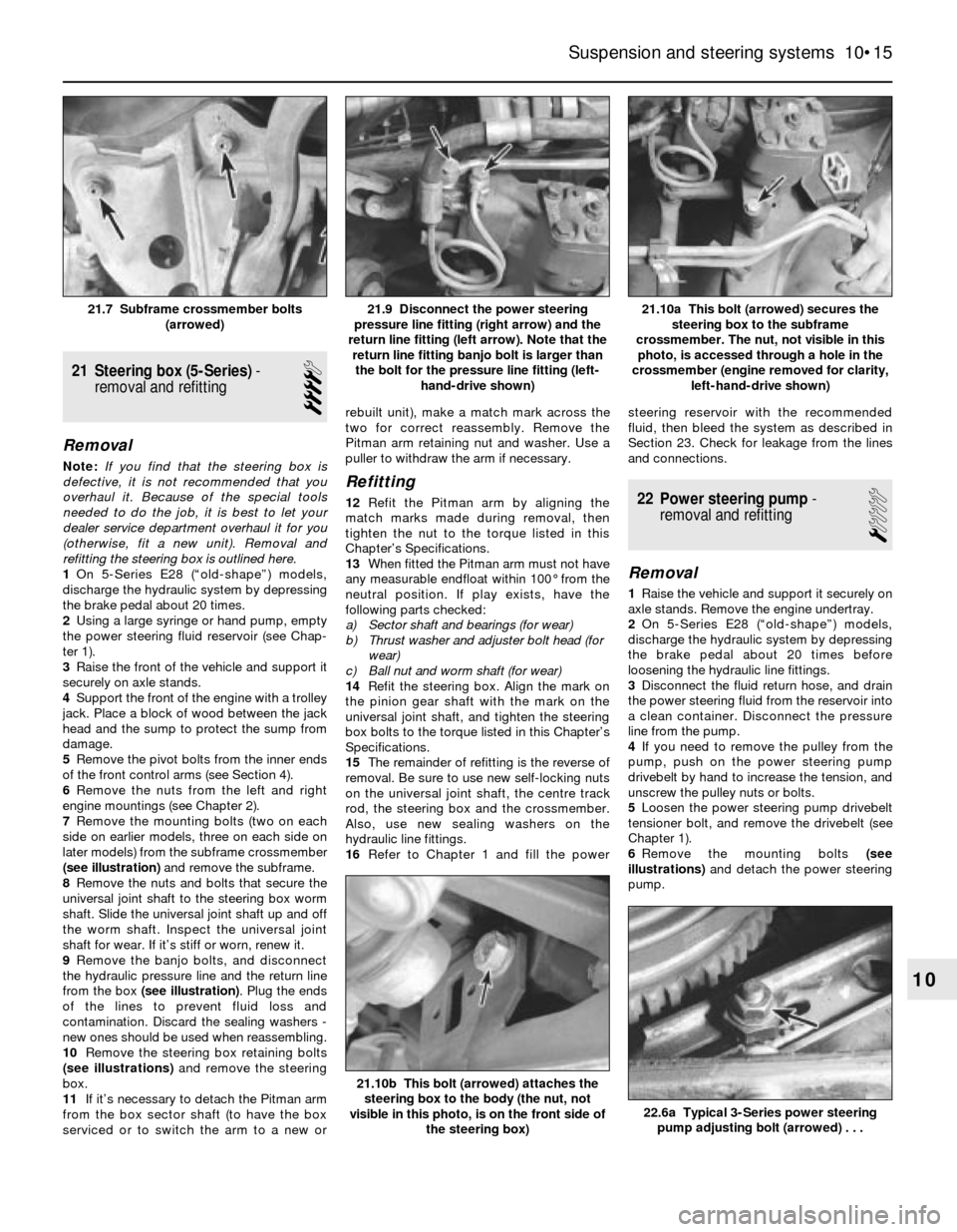
(see illustration)and remove the subframe.
8Remove the nuts and bolts that secure the
universal joint shaft to the steering box worm
shaft. Slide the universal joint shaft up and off
the worm shaft. Inspect the universal joint
shaft for wear. If it’s stiff or worn, renew it.
9Remove the banjo bolts, and disconnect
the hydraulic pressure line and the return line
from the box (see illustration). Plug the ends
of the lines to prevent fluid loss and
contamination. Discard the sealing washers -
new ones should be used when reassembling.
10Remove the steering box retaining bolts
(see illustrations)and remove the steering
box.
11If it’s necessary to detach the Pitman arm
from the box sector shaft (to have the box
serviced or to switch the arm to a new orrebuilt unit), make a match mark across the
two for correct reassembly. Remove the
Pitman arm retaining nut and washer. Use a
puller to withdraw the arm if necessary.
Refitting
12Refit the Pitman arm by aligning the
match marks made during removal, then
tighten the nut to the torque listed in this
Chapter’s Specifications.
13When fitted the Pitman arm must not have
any measurable endfloat within 100° from the
neutral position. If play exists, have the
following parts checked:
a) Sector shaft and bearings (for wear)
b) Thrust washer and adjuster bolt head (for
wear)
c) Ball nut and worm shaft (for wear)
14Refit the steering box. Align the mark on
the pinion gear shaft with the mark on the
universal joint shaft, and tighten the steering
box bolts to the torque listed in this Chapter’s
Specifications.
15The remainder of refitting is the reverse of
removal. Be sure to use new self-locking nuts
on the universal joint shaft, the centre track
rod, the steering box and the crossmember.
Also, use new sealing washers on the
hydraulic line fittings.
16Refer to Chapter 1 and fill the powersteering reservoir with the recommended
fluid, then bleed the system as described in
Section 23. Check for leakage from the lines
and connections.22 Power steering pump-
removal and refitting
1
Removal
1Raise the vehicle and support it securely on
axle stands. Remove the engine undertray.
2On 5-Series E28 (“old-shape”) models,
discharge the hydraulic system by depressing
the brake pedal about 20 times before
loosening the hydraulic line fittings.
3Disconnect the fluid return hose, and drain
the power steering fluid from the reservoir into
a clean container. Disconnect the pressure
line from the pump.
4If you need to remove the pulley from the
pump, push on the power steering pump
drivebelt by hand to increase the tension, and
unscrew the pulley nuts or bolts.
5Loosen the power steering pump drivebelt
tensioner bolt, and remove the drivebelt (see
Chapter 1).
6Remove the mounting bolts (see
illustrations)and detach the power steering
pump.
Suspension and steering systems 10•15
21.10a This bolt (arrowed) secures the
steering box to the subframe
crossmember. The nut, not visible in this
photo, is accessed through a hole in the
crossmember (engine removed for clarity,
left-hand-drive shown)21.9 Disconnect the power steering
pressure line fitting (right arrow) and the
return line fitting (left arrow). Note that the
return line fitting banjo bolt is larger than
the bolt for the pressure line fitting (left-
hand-drive shown)21.7 Subframe crossmember bolts
(arrowed)
22.6a Typical 3-Series power steering
pump adjusting bolt (arrowed) . . .
21.10b This bolt (arrowed) attaches the
steering box to the body (the nut, not
visible in this photo, is on the front side of
the steering box)
10