Check panel BMW 3 SERIES 1985 E30 Owner's Manual
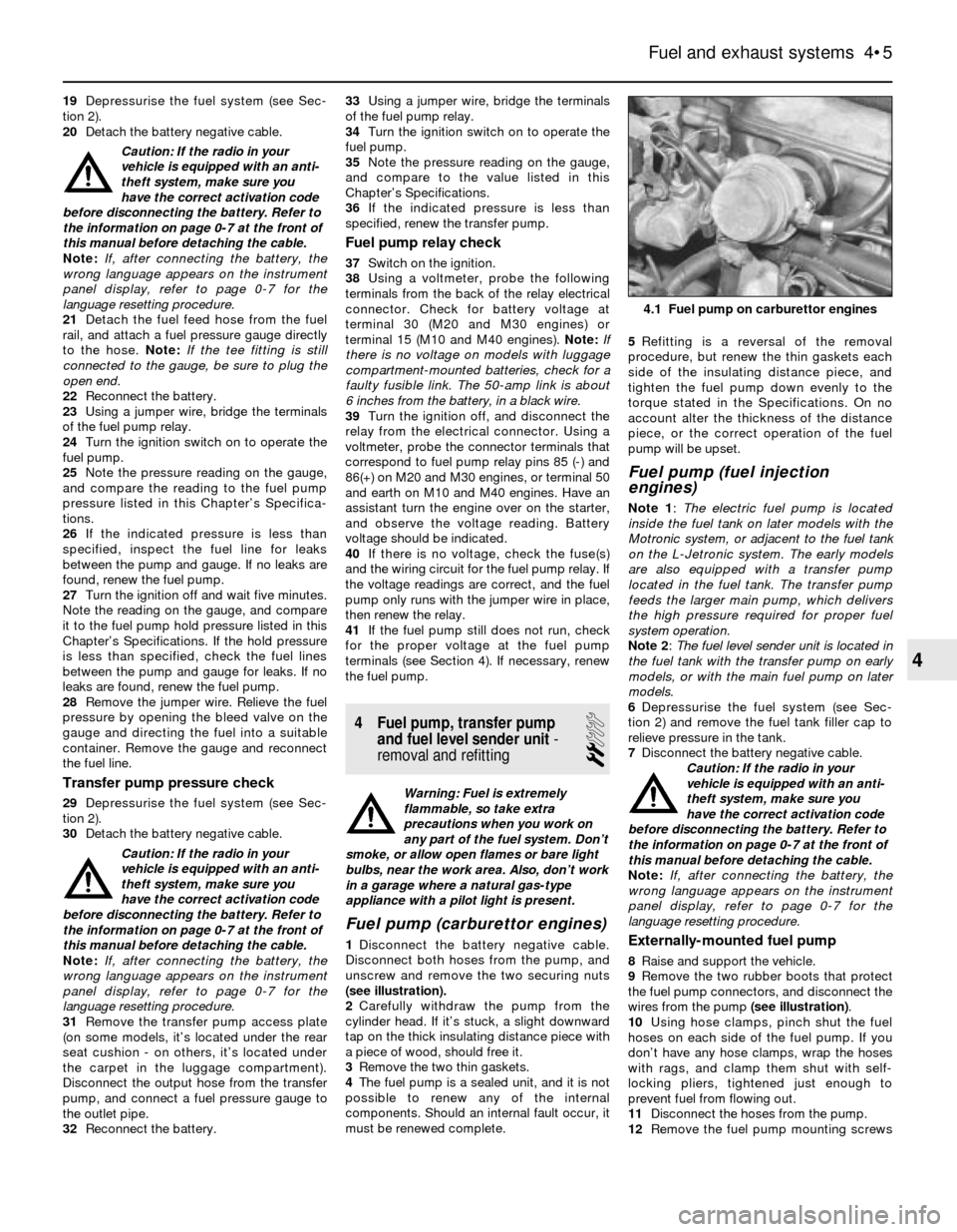
[x] Cancel search | Manufacturer: BMW, Model Year: 1985, Model line: 3 SERIES, Model: BMW 3 SERIES 1985 E30Pages: 228, PDF Size: 7.04 MB
Page 93 of 228
19Depressurise the fuel system (see Sec-
tion 2).
20Detach the battery negative cable.
Caution: If the radio in your
vehicle is equipped with an anti-
theft system, make sure you
have the correct activation code
before disconnecting the battery. Refer to
the information on page 0-7 at the front of
this manual before detaching the cable.
Note: If, after connecting the battery, the
wrong language appears on the instrument
panel display, refer to page 0-7 for the
language resetting procedure.
21Detach the fuel feed hose from the fuel
rail, and attach a fuel pressure gauge directly
to the hose. Note:If the tee fitting is still
connected to the gauge, be sure to plug the
open end.
22Reconnect the battery.
23Using a jumper wire, bridge the terminals
of the fuel pump relay.
24Turn the ignition switch on to operate the
fuel pump.
25Note the pressure reading on the gauge,
and compare the reading to the fuel pump
pressure listed in this Chapter’s Specifica-
tions.
26If the indicated pressure is less than
specified, inspect the fuel line for leaks
between the pump and gauge. If no leaks are
found, renew the fuel pump.
27Turn the ignition off and wait five minutes.
Note the reading on the gauge, and compare
it to the fuel pump hold pressure listed in this
Chapter’s Specifications. If the hold pressure
is less than specified, check the fuel lines
between the pump and gauge for leaks. If no
leaks are found, renew the fuel pump.
28Remove the jumper wire. Relieve the fuel
pressure by opening the bleed valve on the
gauge and directing the fuel into a suitable
container. Remove the gauge and reconnect
the fuel line.
Transfer pump pressure check
29Depressurise the fuel system (see Sec-
tion 2).
30Detach the battery negative cable.
Caution: If the radio in your
vehicle is equipped with an anti-
theft system, make sure you
have the correct activation code
before disconnecting the battery. Refer to
the information on page 0-7 at the front of
this manual before detaching the cable.
Note: If, after connecting the battery, the
wrong language appears on the instrument
panel display, refer to page 0-7 for the
language resetting procedure.
31Remove the transfer pump access plate
(on some models, it’s located under the rear
seat cushion - on others, it’s located under
the carpet in the luggage compartment).
Disconnect the output hose from the transfer
pump, and connect a fuel pressure gauge to
the outlet pipe.
32Reconnect the battery.33Using a jumper wire, bridge the terminals
of the fuel pump relay.
34Turn the ignition switch on to operate the
fuel pump.
35Note the pressure reading on the gauge,
and compare to the value listed in this
Chapter’s Specifications.
36If the indicated pressure is less than
specified, renew the transfer pump.
Fuel pump relay check
37Switch on the ignition.
38Using a voltmeter, probe the following
terminals from the back of the relay electrical
connector. Check for battery voltage at
terminal 30 (M20 and M30 engines) or
terminal 15 (M10 and M40 engines). Note:If
there is no voltage on models with luggage
compartment-mounted batteries, check for a
faulty fusible link. The 50-amp link is about
6 inches from the battery, in a black wire.
39Turn the ignition off, and disconnect the
relay from the electrical connector. Using a
voltmeter, probe the connector terminals that
correspond to fuel pump relay pins 85 (-) and
86(+) on M20 and M30 engines, or terminal 50
and earth on M10 and M40 engines. Have an
assistant turn the engine over on the starter,
and observe the voltage reading. Battery
voltage should be indicated.
40If there is no voltage, check the fuse(s)
and the wiring circuit for the fuel pump relay. If
the voltage readings are correct, and the fuel
pump only runs with the jumper wire in place,
then renew the relay.
41If the fuel pump still does not run, check
for the proper voltage at the fuel pump
terminals (see Section 4). If necessary, renew
the fuel pump.
4 Fuel pump, transfer pump
and fuel level sender unit-
removal and refitting
2
Warning: Fuel is extremely
flammable, so take extra
precautions when you work on
any part of the fuel system. Don’t
smoke, or allow open flames or bare light
bulbs, near the work area. Also, don’t work
in a garage where a natural gas-type
appliance with a pilot light is present.
Fuel pump (carburettor engines)
1Disconnect the battery negative cable.
Disconnect both hoses from the pump, and
unscrew and remove the two securing nuts
(see illustration).
2Carefully withdraw the pump from the
cylinder head. If it’s stuck, a slight downward
tap on the thick insulating distance piece with
a piece of wood, should free it.
3Remove the two thin gaskets.
4The fuel pump is a sealed unit, and it is not
possible to renew any of the internal
components. Should an internal fault occur, it
must be renewed complete.5Refitting is a reversal of the removal
procedure, but renew the thin gaskets each
side of the insulating distance piece, and
tighten the fuel pump down evenly to the
torque stated in the Specifications. On no
account alter the thickness of the distance
piece, or the correct operation of the fuel
pump will be upset.
Fuel pump (fuel injection
engines)
Note 1: The electric fuel pump is located
inside the fuel tank on later models with the
Motronic system, or adjacent to the fuel tank
on the L-Jetronic system. The early models
are also equipped with a transfer pump
located in the fuel tank. The transfer pump
feeds the larger main pump, which delivers
the high pressure required for proper fuel
system operation.
Note 2: The fuel level sender unit is located in
the fuel tank with the transfer pump on early
models, or with the main fuel pump on later
models.
6Depressurise the fuel system (see Sec-
tion 2) and remove the fuel tank filler cap to
relieve pressure in the tank.
7Disconnect the battery negative cable.
Caution: If the radio in your
vehicle is equipped with an anti-
theft system, make sure you
have the correct activation code
before disconnecting the battery. Refer to
the information on page 0-7 at the front of
this manual before detaching the cable.
Note: If, after connecting the battery, the
wrong language appears on the instrument
panel display, refer to page 0-7 for the
language resetting procedure.
Externally-mounted fuel pump
8Raise and support the vehicle.
9Remove the two rubber boots that protect
the fuel pump connectors, and disconnect the
wires from the pump (see illustration).
10Using hose clamps, pinch shut the fuel
hoses on each side of the fuel pump. If you
don’t have any hose clamps, wrap the hoses
with rags, and clamp them shut with self-
locking pliers, tightened just enough to
prevent fuel from flowing out.
11Disconnect the hoses from the pump.
12Remove the fuel pump mounting screws
Fuel and exhaust systems 4•5
4.1 Fuel pump on carburettor engines
4
Page 95 of 228
correct resistance. On L-Jetronic and early
Motronic systems, follow the table below. On
later Motronic systems, connect the
ohmmeter probes onto the fuel level sender
unit terminals that correspond to pins 1 and 3
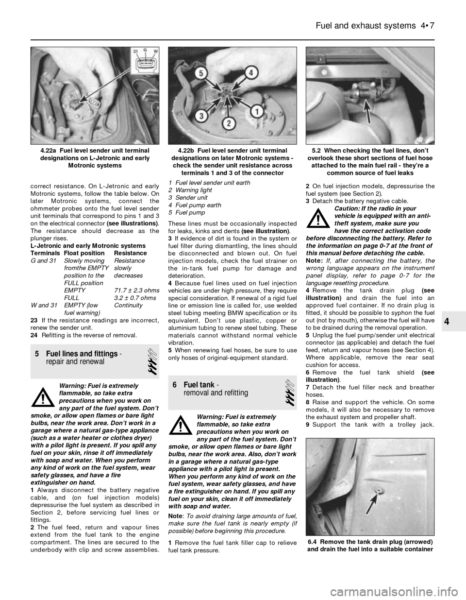
on the electrical connector (see illustrations).
The resistance should decrease as the
plunger rises.
L-Jetronic and early Motronic systems
Terminals Float position Resistance
G and 31 Slowly moving Resistance
fromthe EMPTY slowly
position to the decreases
FULL position
EMPTY 71.7 ± 2.3 ohms
FULL 3.2 ± 0.7 ohms
W and 31 EMPTY (low Continuity
fuel warning)
23If the resistance readings are incorrect,
renew the sender unit.
24Refitting is the reverse of removal.
5 Fuel lines and fittings-
repair and renewal
3
Warning: Fuel is extremely
flammable, so take extra
precautions when you work on
any part of the fuel system. Don’t
smoke, or allow open flames or bare light
bulbs, near the work area. Don’t work in a
garage where a natural gas-type appliance
(such as a water heater or clothes dryer)
with a pilot light is present. If you spill any
fuel on your skin, rinse it off immediately
with soap and water. When you perform
any kind of work on the fuel system, wear
safety glasses, and have a fire
extinguisher on hand.
1Always disconnect the battery negative
cable, and (on fuel injection models)
depressurise the fuel system as described in
Section 2, before servicing fuel lines or
fittings.
2The fuel feed, return and vapour lines
extend from the fuel tank to the engine
compartment. The lines are secured to the
underbody with clip and screw assemblies.These lines must be occasionally inspected
for leaks, kinks and dents (see illustration).
3If evidence of dirt is found in the system or
fuel filter during dismantling, the lines should
be disconnected and blown out. On fuel
injection models, check the fuel strainer on
the in-tank fuel pump for damage and
deterioration.
4Because fuel lines used on fuel injection
vehicles are under high pressure, they require
special consideration. If renewal of a rigid fuel
line or emission line is called for, use welded
steel tubing meeting BMW specification or its
equivalent. Don’t use plastic, copper or
aluminium tubing to renew steel tubing. These
materials cannot withstand normal vehicle
vibration.
5When renewing fuel hoses, be sure to use
only hoses of original-equipment standard.6 Fuel tank-
removal and refitting
3
Warning: Fuel is extremely
flammable, so take extra
precautions when you work on
any part of the fuel system. Don’t
smoke, or allow open flames or bare light
bulbs, near the work area. Also, don’t work
in a garage where a natural gas-type
appliance with a pilot light is present.
When you perform any kind of work on the
fuel system, wear safety glasses, and have
a fire extinguisher on hand. If you spill any
fuel on your skin, clean it off immediately
with soap and water.
Note: To avoid draining large amounts of fuel,
make sure the fuel tank is nearly empty (if
possible) before beginning this procedure.
1Remove the fuel tank filler cap to relieve
fuel tank pressure.2On fuel injection models, depressurise the
fuel system (see Section 2).
3Detach the battery negative cable.
Caution: If the radio in your
vehicle is equipped with an anti-
theft system, make sure you
have the correct activation code
before disconnecting the battery. Refer to
the information on page 0-7 at the front of
this manual before detaching the cable.
Note: If, after connecting the battery, the
wrong language appears on the instrument
panel display, refer to page 0-7 for the
language resetting procedure.
4Remove the tank drain plug (see
illustration)and drain the fuel into an
approved fuel container. If no drain plug is
fitted, it should be possible to syphon the fuel
out (not by mouth), otherwise the fuel will have
to be drained during the removal operation.
5Unplug the fuel pump/sender unit electrical
connector (as applicable) and detach the fuel
feed, return and vapour hoses (see Section 4).
Where applicable, remove the rear seat
cushion for access.
6Remove the fuel tank shield (see
illustration).
7Detach the fuel filler neck and breather
hoses.
8Raise and support the vehicle. On some
models, it will also be necessary to remove
the exhaust system and propeller shaft.
9Support the tank with a trolley jack.
Fuel and exhaust systems 4•7
4.22b Fuel level sender unit terminal
designations on later Motronic systems -
check the sender unit resistance across
terminals 1 and 3 of the connector
1 Fuel level sender unit earth
2 Warning light
3 Sender unit
4 Fuel pump earth
5 Fuel pump4.22a Fuel level sender unit terminal
designations on L-Jetronic and early
Motronic systems
6.4 Remove the tank drain plug (arrowed)
and drain the fuel into a suitable container
5.2 When checking the fuel lines, don’t
overlook these short sections of fuel hose
attached to the main fuel rail - they’re a
common source of fuel leaks
4
Page 103 of 228
8Check the fuel system pressure (see
Section 3).
9If these checks do not locate the problem,
take the vehicle to a BMW dealer, who will be
able to read the fault codes stored in the ECU,
using special equipment.
16 Airflow meter- check,
removal and refitting
2
Check (L-Jetronic systems)
1Remove the duct from the intake end of the
airflow meter. Carefully open and close the
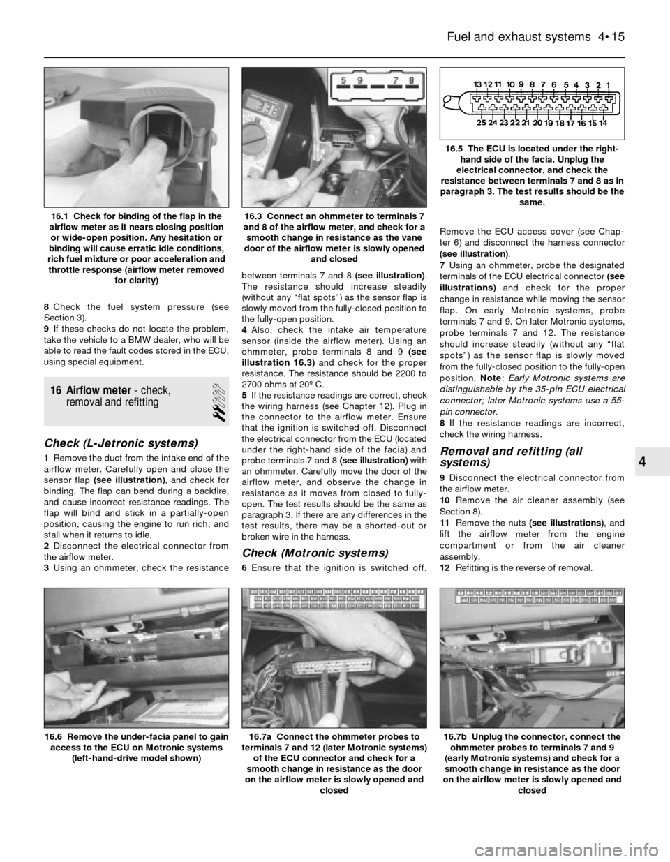
sensor flap (see illustration), and check for
binding. The flap can bend during a backfire,
and cause incorrect resistance readings. The
flap will bind and stick in a partially-open
position, causing the engine to run rich, and
stall when it returns to idle.
2Disconnect the electrical connector from
the airflow meter.
3Using an ohmmeter, check the resistancebetween terminals 7 and 8 (see illustration).
The resistance should increase steadily
(without any “flat spots”) as the sensor flap is
slowly moved from the fully-closed position to
the fully-open position.
4Also, check the intake air temperature
sensor (inside the airflow meter). Using an
ohmmeter, probe terminals 8 and 9 (see
illustration 16.3)and check for the proper
resistance. The resistance should be 2200 to
2700 ohms at 20º C.
5If the resistance readings are correct, check
the wiring harness (see Chapter 12). Plug in
the connector to the airflow meter. Ensure
that the ignition is switched off. Disconnect
the electrical connector from the ECU (located
under the right-hand side of the facia) and
probe terminals 7 and 8 (see illustration)with
an ohmmeter. Carefully move the door of the
airflow meter, and observe the change in
resistance as it moves from closed to fully-
open. The test results should be the same as
paragraph 3. If there are any differences in the
test results, there may be a shorted-out or
broken wire in the harness.
Check (Motronic systems)
6Ensure that the ignition is switched off.Remove the ECU access cover (see Chap-
ter 6) and disconnect the harness connector
(see illustration).
7Using an ohmmeter, probe the designated
terminals of the ECU electrical connector (see
illustrations)and check for the proper
change in resistance while moving the sensor
flap. On early Motronic systems, probe
terminals 7 and 9. On later Motronic systems,
probe terminals 7 and 12. The resistance
should increase steadily (without any “flat
spots”) as the sensor flap is slowly moved
from the fully-closed position to the fully-open
position. Note: Early Motronic systems are
distinguishable by the 35-pin ECU electrical
connector; later Motronic systems use a 55-
pin connector.
8If the resistance readings are incorrect,
check the wiring harness.
Removal and refitting (all
systems)
9Disconnect the electrical connector from
the airflow meter.
10Remove the air cleaner assembly (see
Section 8).
11Remove the nuts (see illustrations), and
lift the airflow meter from the engine
compartment or from the air cleaner
assembly.
12Refitting is the reverse of removal.
Fuel and exhaust systems 4•15
16.5 The ECU is located under the right-
hand side of the facia. Unplug the
electrical connector, and check the
resistance between terminals 7 and 8 as in
paragraph 3. The test results should be the
same.
16.3 Connect an ohmmeter to terminals 7
and 8 of the airflow meter, and check for a
smooth change in resistance as the vane
door of the airflow meter is slowly opened
and closed16.1 Check for binding of the flap in the
airflow meter as it nears closing position
or wide-open position. Any hesitation or
binding will cause erratic idle conditions,
rich fuel mixture or poor acceleration and
throttle response (airflow meter removed
for clarity)
16.7b Unplug the connector, connect the
ohmmeter probes to terminals 7 and 9
(early Motronic systems) and check for a
smooth change in resistance as the door
on the airflow meter is slowly opened and
closed16.7a Connect the ohmmeter probes to
terminals 7 and 12 (later Motronic systems)
of the ECU connector and check for a
smooth change in resistance as the door
on the airflow meter is slowly opened and
closed16.6 Remove the under-facia panel to gain
access to the ECU on Motronic systems
(left-hand-drive model shown)
4
Page 104 of 228
17 Throttle body- check,
removal and refitting
2
Check
1Detach the air intake duct from the throttle
body (see Section 8) and move the duct out of
the way.
2Have an assistant depress the throttle
pedal while you watch the throttle valve.
Check that the throttle valve moves smoothly
when the throttle is moved from closed (idle
position) to fully-open (wide-open throttle).
3If the throttle valve is not working properly,
renew the throttle body unit.
Warning: Wait until the engine is
completely cool before beginning
this procedure.
Caution: If the radio in your
vehicle is equipped with an anti-
theft system, make sure you
have the correct activation code
before disconnecting the battery. Refer to
the information on page 0-7 at the front of
this manual before detaching the cable.
Note: If, after connecting the battery, the
wrong language appears on the instrument
panel display, refer to page 0-7 for the
language resetting procedure.
Removal and refitting
4Detach the battery negative cable.
5Detach the air intake duct from the throttle
body, and place to one side.
6Detach the accelerator cable from the
throttle body (see Section 9).
7Detach the cruise control cable, if applicable.
8Clearly label all electrical connectors
(throttle position sensor, cold start injector,
idle air stabiliser, etc), then unplug them.
9Clearly label all vacuum hoses, then detach
them.
10Unscrew the radiator or expansion tank
cap to relieve any residual pressure in the
cooling system, then refit it. Clamp shut the
coolant hoses, then loosen the hose clamps
and detach the hoses. Be prepared for some
coolant leakage.11Remove the throttle body mounting nuts
(upper) and bolts (lower), and detach the
throttle body from the air intake plenum (see
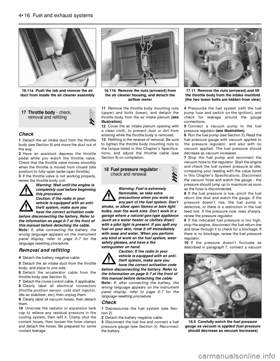
illustration).
12Cover the air intake plenum opening with
a clean cloth, to prevent dust or dirt from
entering while the throttle body is removed.
13Refitting is the reverse of removal. Be sure
to tighten the throttle body mounting nuts to
the torque listed in this Chapter’s Specifica-
tions, and adjust the throttle cable (see
Section 9) on completion.
18 Fuel pressure regulator-
check and renewal
3
Warning: Fuel is extremely
flammable, so take extra
precautions when you work on
any part of the fuel system. Don’t
smoke, or allow open flames or bare light
bulbs, near the work area. Don’t work in a
garage where a natural gas-type appliance
(such as a water heater or clothes dryer)
with a pilot light is present. If you spill any
fuel on your skin, rinse it off immediately
with soap and water. When you perform
any kind of work on the fuel system, wear
safety glasses, and have a fire
extinguisher on hand.
Caution: If the radio in your
vehicle is equipped with an anti-
theft system, make sure you
have the correct activation code
before disconnecting the battery. Refer to
the information on page 0-7 at the front of
this manual before detaching the cable.
Note: If, after connecting the battery, the
wrong language appears on the instrument
panel display, refer to page 0-7 for the
language resetting procedure.
Check
1Depressurise the fuel system (see Sec-
tion 2).
2Detach the battery negative cable.
3Disconnect the fuel line and connect a fuel
pressure gauge (see Section 3). Reconnect
the battery.4Pressurise the fuel system (refit the fuel
pump fuse and switch on the ignition), and
check for leakage around the gauge
connections.
5Connect a vacuum pump to the fuel
pressure regulator (see illustration).
6Run the fuel pump (see Section 3). Read the
fuel pressure gauge with vacuum applied to
the pressure regulator, and also with no
vacuum applied. The fuel pressure should
decrease as vacuum increases.
7Stop the fuel pump and reconnect the
vacuum hose to the regulator. Start the engine
and check the fuel system pressure at idle,
comparing your reading with the value listed
in this Chapter’s Specifications. Disconnect
the vacuum hose and watch the gauge - the
pressure should jump up to maximum as soon
as the hose is disconnected.
8If the fuel pressure is low, pinch the fuel
return line shut and watch the gauge. If the
pressure doesn’t rise, the fuel pump is
defective, or there is a restriction in the fuel
feed line. If the pressure now rises sharply,
renew the pressure regulator.
9If the indicated fuel pressure is too high,
stop the engine, disconnect the fuel return line
and blow through it to check for a blockage. If
there is no blockage, renew the fuel pressure
regulator.
10If the pressure doesn’t fluctuate as
described in paragraph 7, connect a vacuum
4•16 Fuel and exhaust systems
18.5 Carefully watch the fuel pressure
gauge as vacuum is applied (fuel pressure
should decrease as vacuum increases)
17.11 Remove the nuts (arrowed) and lift
the throttle body from the intake manifold
(the two lower bolts are hidden from view)16.11b Remove the nuts (arrowed) from
the air cleaner housing, and detach the
airflow meter16.11a Push the tab and remove the air
duct from inside the air cleaner assembly
Page 105 of 228
gauge to the pressure regulator vacuum hose,
and check for vacuum (engine idling).
11If there is vacuum present, renew the fuel
pressure regulator.
12If there isn’t any reading on the gauge,
check the hose and its port for a leak or a
restriction.
Renewal
13Depressurise the fuel system (see Sec-
tion 2).
14Detach the battery negative cable.
Caution: If the radio in your
vehicle is equipped with an anti-
theft system, make sure you
have the correct activation code
before disconnecting the battery. Refer to
the information on page 0-7 at the front of
this manual before detaching the cable.
Note: If, after connecting the battery, the
wrong language appears on the instrument
panel display, refer to page 0-7 for the
language resetting procedure.
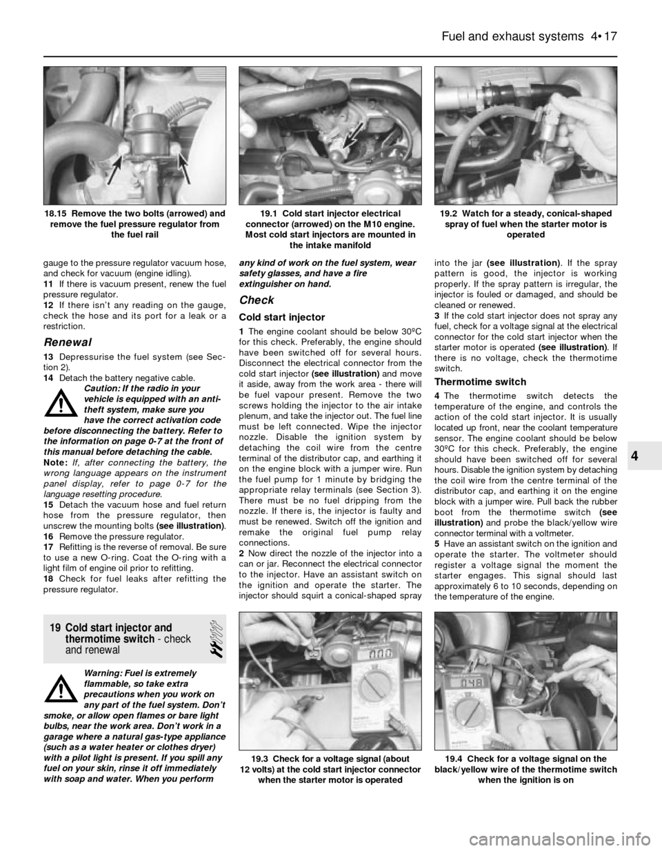
15Detach the vacuum hose and fuel return
hose from the pressure regulator, then
unscrew the mounting bolts (see illustration).
16Remove the pressure regulator.
17Refitting is the reverse of removal. Be sure
to use a new O-ring. Coat the O-ring with a
light film of engine oil prior to refitting.
18Check for fuel leaks after refitting the
pressure regulator.
19 Cold start injector and
thermotime switch- check
and renewal
2
Warning: Fuel is extremely
flammable, so take extra
precautions when you work on
any part of the fuel system. Don’t
smoke, or allow open flames or bare light
bulbs, near the work area. Don’t work in a
garage where a natural gas-type appliance
(such as a water heater or clothes dryer)
with a pilot light is present. If you spill any
fuel on your skin, rinse it off immediately
with soap and water. When you performany kind of work on the fuel system, wear
safety glasses, and have a fire
extinguisher on hand.
Check
Cold start injector
1The engine coolant should be below 30ºC
for this check. Preferably, the engine should
have been switched off for several hours.
Disconnect the electrical connector from the
cold start injector (see illustration)and move
it aside, away from the work area - there will
be fuel vapour present. Remove the two
screws holding the injector to the air intake
plenum, and take the injector out. The fuel line
must be left connected. Wipe the injector
nozzle. Disable the ignition system by
detaching the coil wire from the centre
terminal of the distributor cap, and earthing it
on the engine block with a jumper wire. Run
the fuel pump for 1 minute by bridging the
appropriate relay terminals (see Section 3).
There must be no fuel dripping from the
nozzle. If there is, the injector is faulty and
must be renewed. Switch off the ignition and
remake the original fuel pump relay
connections.
2Now direct the nozzle of the injector into a
can or jar. Reconnect the electrical connector
to the injector. Have an assistant switch on
the ignition and operate the starter. The
injector should squirt a conical-shaped sprayinto the jar (see illustration). If the spray
pattern is good, the injector is working
properly. If the spray pattern is irregular, the
injector is fouled or damaged, and should be
cleaned or renewed.
3If the cold start injector does not spray any
fuel, check for a voltage signal at the electrical
connector for the cold start injector when the
starter motor is operated (see illustration). If
there is no voltage, check the thermotime
switch.
Thermotime switch
4The thermotime switch detects the
temperature of the engine, and controls the
action of the cold start injector. It is usually
located up front, near the coolant temperature
sensor. The engine coolant should be below
30ºC for this check. Preferably, the engine
should have been switched off for several
hours. Disable the ignition system by detaching
the coil wire from the centre terminal of the
distributor cap, and earthing it on the engine
block with a jumper wire. Pull back the rubber
boot from the thermotime switch (see
illustration)and probe the black/yellow wire
connector terminal with a voltmeter.
5Have an assistant switch on the ignition and
operate the starter. The voltmeter should
register a voltage signal the moment the
starter engages. This signal should last
approximately 6 to 10 seconds, depending on
the temperature of the engine.
Fuel and exhaust systems 4•17
19.2 Watch for a steady, conical-shaped
spray of fuel when the starter motor is
operated19.1 Cold start injector electrical
connector (arrowed) on the M10 engine.
Most cold start injectors are mounted in
the intake manifold18.15 Remove the two bolts (arrowed) and
remove the fuel pressure regulator from
the fuel rail
19.4 Check for a voltage signal on the
black/yellow wire of the thermotime switch
when the ignition is on19.3 Check for a voltage signal (about
12 volts) at the cold start injector connector
when the starter motor is operated
4
Page 112 of 228
1 General information
The engine electrical systems include all
ignition, charging and starting components.
Because of their engine-related functions,
these components are discussed separately
from body-related electrical devices such as
the lights, the instruments, etc. (which are
included in Chapter 12).
Always observe the following precautions
when working on the electrical systems:
a) Be extremely careful when servicing
engine electrical components. They are
easily damaged if improperly checked,
connected or handled.
b) Never leave the ignition switched on for
long periods of time with the engine off.
c) Don’t disconnect the battery cables while
the engine is running.
d) Observe the rules when jump-starting
your vehicle. Read the precautions at the
front of this manual.
e) Always disconnect the battery negative
cable first, and connect it last, to reduce
the risk of accidental short-circuits.
f) Don’t charge the battery with the cables
connected to the terminals.
It’s also a good idea to review the safety-
related information regarding the engine
electrical systems in the “Safety first”section
near the front of this manual before beginning
any operation included in this Chapter.
Caution: If the radio in your
vehicle is equipped with an anti-
theft system, make sure you
have the correct activation code
before disconnecting the battery. Refer to
the information on page 0-7 at the front of
this manual before detaching the cable.
Note: If, after connecting the battery, the
wrong language appears on the instrument
panel display, refer to page 0-7 for the
language resetting procedure.
2 Battery-
emergency jump starting
1
Refer to the “Jump starting”procedure at
the front of this manual.
3 Battery- removal and refitting
1
Note:Depending on the model, the battery
may be located in the engine compartment, in
the rear luggage compartment, or under the
rear seat. Consult your owners handbook for
the location of the battery, if not already
known to you.Caution: If the radio in your
vehicle is equipped with an anti-
theft system, make sure you
have the correct activation code
before disconnecting the battery. Refer to
the information on page 0-7 at the front of
this manual before detaching the cable.
Note: If, after connecting the battery, the
wrong language appears on the instrument
panel display, refer to page 0-7 for the
language resetting procedure.
1Disconnect the battery negative cable.
2Detach the cable from the positive terminal.
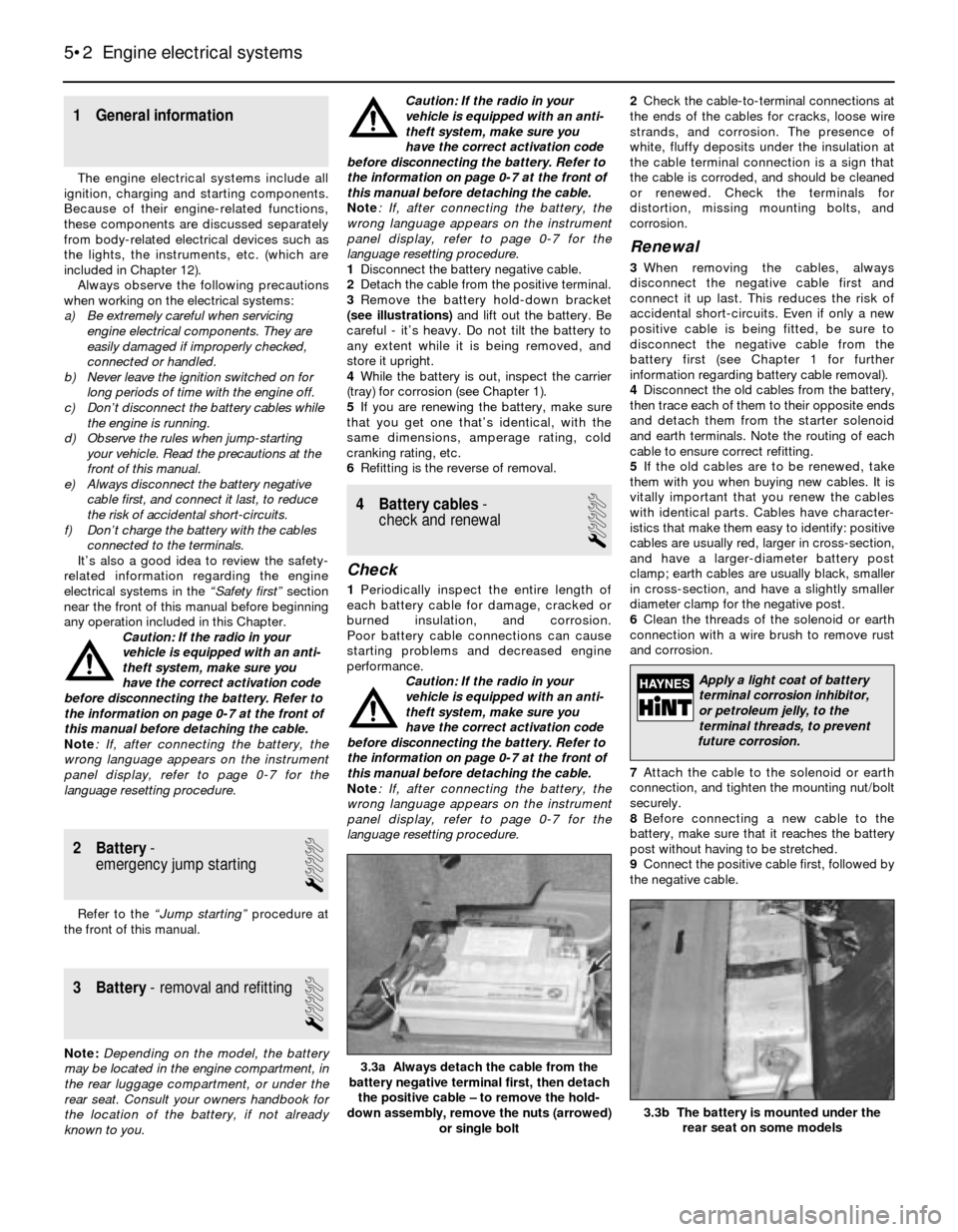
3Remove the battery hold-down bracket
(see illustrations)and lift out the battery. Be
careful - it’s heavy. Do not tilt the battery to
any extent while it is being removed, and
store it upright.
4While the battery is out, inspect the carrier
(tray) for corrosion (see Chapter 1).
5If you are renewing the battery, make sure
that you get one that’s identical, with the
same dimensions, amperage rating, cold
cranking rating, etc.
6Refitting is the reverse of removal.
4 Battery cables-
check and renewal
1
Check
1Periodically inspect the entire length of
each battery cable for damage, cracked or
burned insulation, and corrosion.
Poor battery cable connections can cause
starting problems and decreased engine
performance.
Caution: If the radio in your
vehicle is equipped with an anti-
theft system, make sure you
have the correct activation code
before disconnecting the battery. Refer to
the information on page 0-7 at the front of
this manual before detaching the cable.
Note: If, after connecting the battery, the
wrong language appears on the instrument
panel display, refer to page 0-7 for the
language resetting procedure.2Check the cable-to-terminal connections at
the ends of the cables for cracks, loose wire
strands, and corrosion. The presence of
white, fluffy deposits under the insulation at
the cable terminal connection is a sign that
the cable is corroded, and should be cleaned
or renewed. Check the terminals for
distortion, missing mounting bolts, and
corrosion.
Renewal
3When removing the cables, always
disconnect the negative cable first and
connect it up last. This reduces the risk of
accidental short-circuits. Even if only a new
positive cable is being fitted, be sure to
disconnect the negative cable from the
battery first (see Chapter 1 for further
information regarding battery cable removal).
4Disconnect the old cables from the battery,
then trace each of them to their opposite ends
and detach them from the starter solenoid
and earth terminals. Note the routing of each
cable to ensure correct refitting.
5If the old cables are to be renewed, take
them with you when buying new cables. It is
vitally important that you renew the cables
with identical parts. Cables have character-
istics that make them easy to identify: positive
cables are usually red, larger in cross-section,
and have a larger-diameter battery post
clamp; earth cables are usually black, smaller
in cross-section, and have a slightly smaller
diameter clamp for the negative post.
6Clean the threads of the solenoid or earth
connection with a wire brush to remove rust
and corrosion.
7Attach the cable to the solenoid or earth
connection, and tighten the mounting nut/bolt
securely.
8Before connecting a new cable to the
battery, make sure that it reaches the battery
post without having to be stretched.
9Connect the positive cable first, followed by
the negative cable.
5•2 Engine electrical systems
3.3b The battery is mounted under the
rear seat on some models
3.3a Always detach the cable from the
battery negative terminal first, then detach
the positive cable – to remove the hold-
down assembly, remove the nuts (arrowed)
or single bolt
Apply a light coat of battery
terminal corrosion inhibitor,
or petroleum jelly, to the
terminal threads, to prevent
future corrosion.
Page 117 of 228
8Use a digital voltmeter for the following
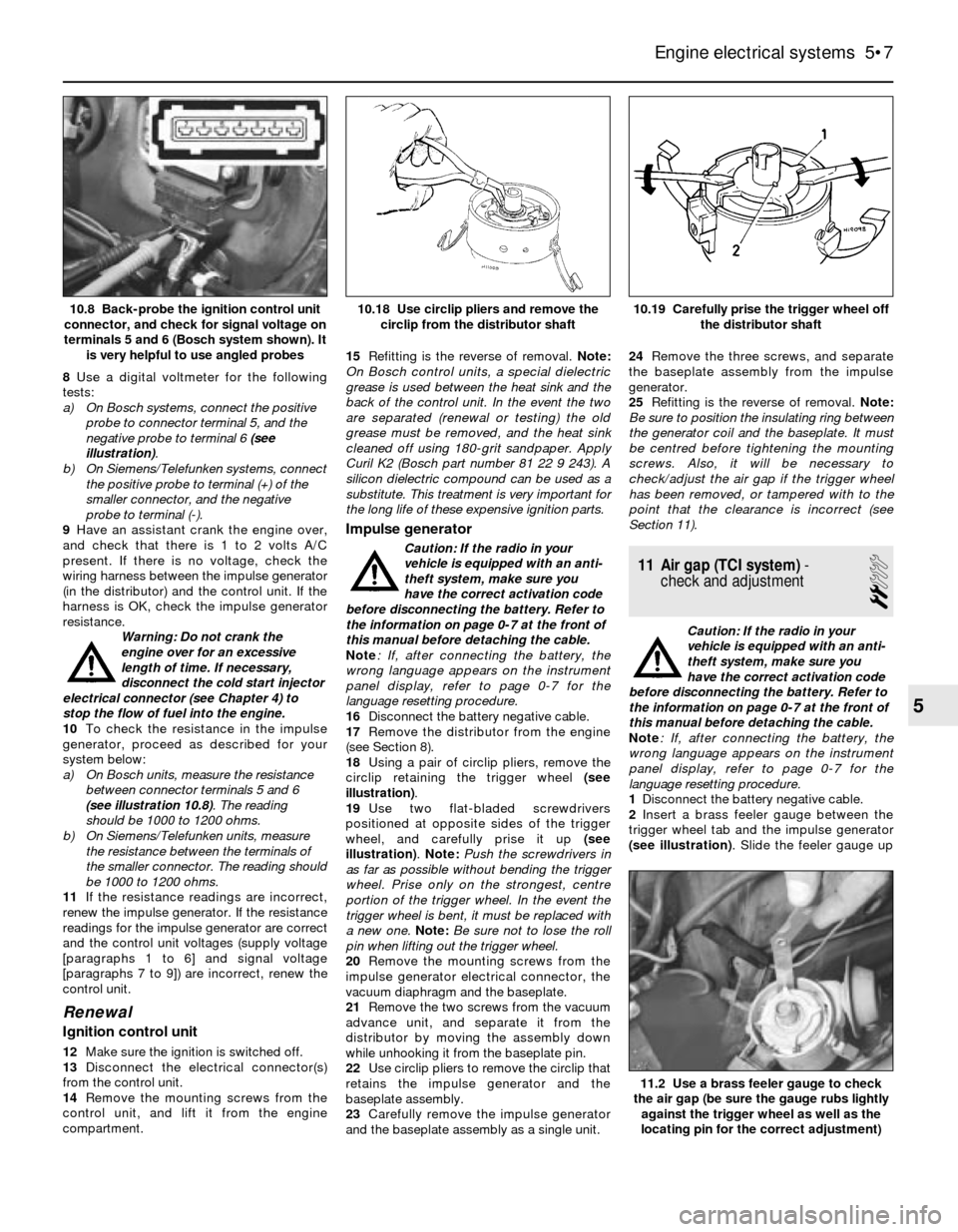
tests:
a) On Bosch systems, connect the positive
probe to connector terminal 5, and the
negative probe to terminal 6 (see
illustration).
b) On Siemens/Telefunken systems, connect
the positive probe to terminal (+) of the
smaller connector, and the negative
probe to terminal (-).
9Have an assistant crank the engine over,
and check that there is 1 to 2 volts A/C
present. If there is no voltage, check the
wiring harness between the impulse generator
(in the distributor) and the control unit. If the
harness is OK, check the impulse generator
resistance.
Warning: Do not crank the
engine over for an excessive
length of time. If necessary,
disconnect the cold start injector
electrical connector (see Chapter 4) to
stop the flow of fuel into the engine.
10To check the resistance in the impulse
generator, proceed as described for your
system below:
a) On Bosch units, measure the resistance
between connector terminals 5 and 6
(see illustration 10.8). The reading
should be 1000 to 1200 ohms.
b) On Siemens/Telefunken units, measure
the resistance between the terminals of
the smaller connector. The reading should
be 1000 to 1200 ohms.
11If the resistance readings are incorrect,
renew the impulse generator. If the resistance
readings for the impulse generator are correct
and the control unit voltages (supply voltage
[paragraphs 1 to 6] and signal voltage
[paragraphs 7 to 9]) are incorrect, renew the
control unit.
Renewal
Ignition control unit
12Make sure the ignition is switched off.
13Disconnect the electrical connector(s)
from the control unit.
14Remove the mounting screws from the
control unit, and lift it from the engine
compartment.15Refitting is the reverse of removal. Note:
On Bosch control units, a special dielectric
grease is used between the heat sink and the
back of the control unit. In the event the two
are separated (renewal or testing) the old
grease must be removed, and the heat sink
cleaned off using 180-grit sandpaper. Apply
Curil K2 (Bosch part number 81 22 9 243). A
silicon dielectric compound can be used as a
substitute. This treatment is very important for
the long life of these expensive ignition parts.
Impulse generator
Caution: If the radio in your
vehicle is equipped with an anti-
theft system, make sure you
have the correct activation code
before disconnecting the battery. Refer to
the information on page 0-7 at the front of
this manual before detaching the cable.
Note: If, after connecting the battery, the
wrong language appears on the instrument
panel display, refer to page 0-7 for the
language resetting procedure.
16Disconnect the battery negative cable.
17Remove the distributor from the engine
(see Section 8).
18Using a pair of circlip pliers, remove the
circlip retaining the trigger wheel (see
illustration).
19Use two flat-bladed screwdrivers
positioned at opposite sides of the trigger
wheel, and carefully prise it up (see
illustration). Note: Push the screwdrivers in
as far as possible without bending the trigger
wheel. Prise only on the strongest, centre
portion of the trigger wheel. In the event the
trigger wheel is bent, it must be replaced with
a new one. Note:Be sure not to lose the roll
pin when lifting out the trigger wheel.
20Remove the mounting screws from the
impulse generator electrical connector, the
vacuum diaphragm and the baseplate.
21Remove the two screws from the vacuum
advance unit, and separate it from the
distributor by moving the assembly down
while unhooking it from the baseplate pin.
22Use circlip pliers to remove the circlip that
retains the impulse generator and the
baseplate assembly.
23Carefully remove the impulse generator
and the baseplate assembly as a single unit.24Remove the three screws, and separate
the baseplate assembly from the impulse
generator.
25Refitting is the reverse of removal. Note:
Be sure to position the insulating ring between
the generator coil and the baseplate. It must
be centred before tightening the mounting
screws. Also, it will be necessary to
check/adjust the air gap if the trigger wheel
has been removed, or tampered with to the
point that the clearance is incorrect (see
Section 11).
11 Air gap (TCI system)-
check and adjustment
2
Caution: If the radio in your
vehicle is equipped with an anti-
theft system, make sure you
have the correct activation code
before disconnecting the battery. Refer to
the information on page 0-7 at the front of
this manual before detaching the cable.
Note: If, after connecting the battery, the
wrong language appears on the instrument
panel display, refer to page 0-7 for the
language resetting procedure.
1Disconnect the battery negative cable.
2Insert a brass feeler gauge between the
trigger wheel tab and the impulse generator
(see illustration). Slide the feeler gauge up
Engine electrical systems 5•7
10.19 Carefully prise the trigger wheel off
the distributor shaft10.18 Use circlip pliers and remove the
circlip from the distributor shaft10.8 Back-probe the ignition control unit
connector, and check for signal voltage on
terminals 5 and 6 (Bosch system shown). It
is very helpful to use angled probes
11.2 Use a brass feeler gauge to check
the air gap (be sure the gauge rubs lightly
against the trigger wheel as well as the
locating pin for the correct adjustment)
5
Page 119 of 228
Withdraw the sensor from its bracket and
remove it.
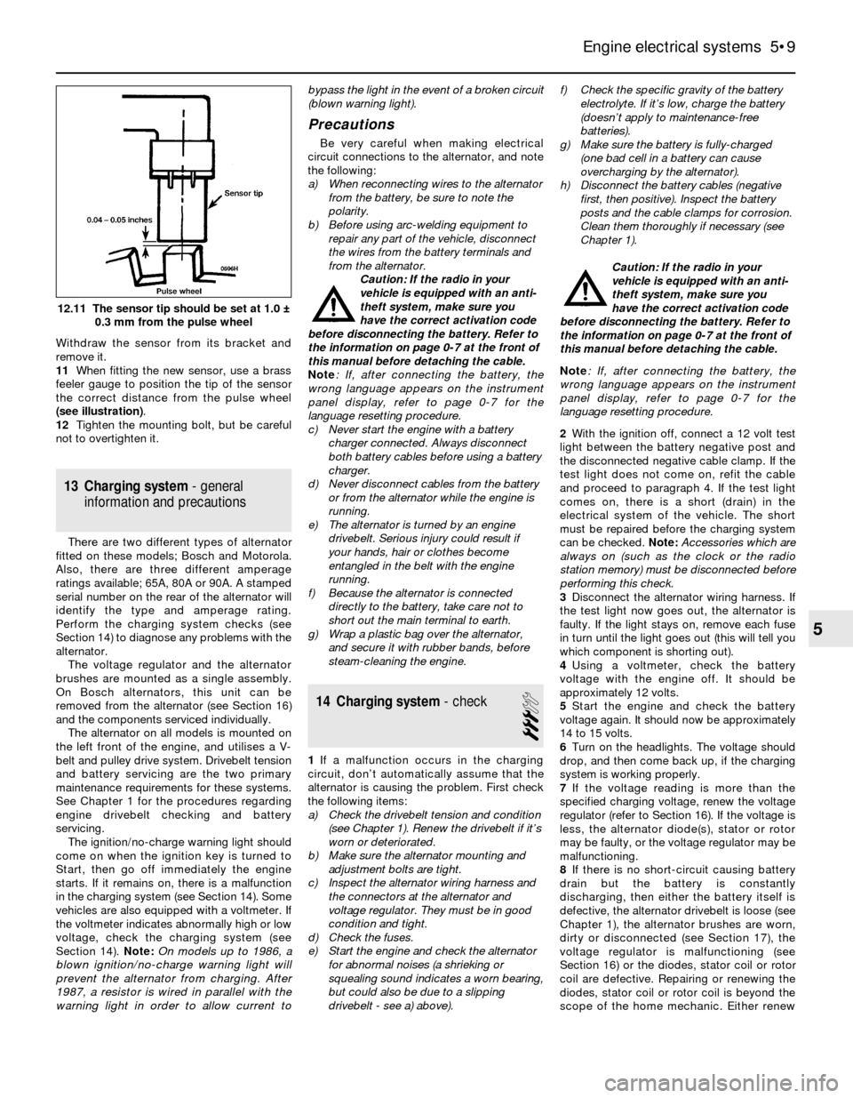
11When fitting the new sensor, use a brass
feeler gauge to position the tip of the sensor
the correct distance from the pulse wheel
(see illustration).
12Tighten the mounting bolt, but be careful
not to overtighten it.
13 Charging system- general
information and precautions
There are two different types of alternator
fitted on these models; Bosch and Motorola.
Also, there are three different amperage
ratings available; 65A, 80A or 90A. A stamped
serial number on the rear of the alternator will
identify the type and amperage rating.
Perform the charging system checks (see
Section 14) to diagnose any problems with the
alternator.
The voltage regulator and the alternator
brushes are mounted as a single assembly.
On Bosch alternators, this unit can be
removed from the alternator (see Section 16)
and the components serviced individually.
The alternator on all models is mounted on
the left front of the engine, and utilises a V-
belt and pulley drive system. Drivebelt tension
and battery servicing are the two primary
maintenance requirements for these systems.
See Chapter 1 for the procedures regarding
engine drivebelt checking and battery
servicing.
The ignition/no-charge warning light should
come on when the ignition key is turned to
Start, then go off immediately the engine
starts. If it remains on, there is a malfunction
in the charging system (see Section 14). Some
vehicles are also equipped with a voltmeter. If
the voltmeter indicates abnormally high or low
voltage, check the charging system (see
Section 14). Note:On models up to 1986, a
blown ignition/no-charge warning light will
prevent the alternator from charging. After
1987, a resistor is wired in parallel with the
warning light in order to allow current tobypass the light in the event of a broken circuit
(blown warning light).
Precautions
Be very careful when making electrical
circuit connections to the alternator, and note
the following:
a) When reconnecting wires to the alternator
from the battery, be sure to note the
polarity.
b) Before using arc-welding equipment to
repair any part of the vehicle, disconnect
the wires from the battery terminals and
from the alternator.
Caution: If the radio in your
vehicle is equipped with an anti-
theft system, make sure you
have the correct activation code
before disconnecting the battery. Refer to
the information on page 0-7 at the front of
this manual before detaching the cable.
Note: If, after connecting the battery, the
wrong language appears on the instrument
panel display, refer to page 0-7 for the
language resetting procedure.
c) Never start the engine with a battery
charger connected. Always disconnect
both battery cables before using a battery
charger.
d) Never disconnect cables from the battery
or from the alternator while the engine is
running.
e) The alternator is turned by an engine
drivebelt. Serious injury could result if
your hands, hair or clothes become
entangled in the belt with the engine
running.
f) Because the alternator is connected
directly to the battery, take care not to
short out the main terminal to earth.
g) Wrap a plastic bag over the alternator,
and secure it with rubber bands, before
steam-cleaning the engine.
14 Charging system- check
3
1If a malfunction occurs in the charging
circuit, don’t automatically assume that the
alternator is causing the problem. First check
the following items:
a) Check the drivebelt tension and condition
(see Chapter 1). Renew the drivebelt if it’s
worn or deteriorated.
b) Make sure the alternator mounting and
adjustment bolts are tight.
c) Inspect the alternator wiring harness and
the connectors at the alternator and
voltage regulator. They must be in good
condition and tight.
d) Check the fuses.
e) Start the engine and check the alternator
for abnormal noises (a shrieking or
squealing sound indicates a worn bearing,
but could also be due to a slipping
drivebelt - see a) above).f) Check the specific gravity of the battery
electrolyte. If it’s low, charge the battery
(doesn’t apply to maintenance-free
batteries).
g) Make sure the battery is fully-charged
(one bad cell in a battery can cause
overcharging by the alternator).
h) Disconnect the battery cables (negative
first, then positive). Inspect the battery
posts and the cable clamps for corrosion.
Clean them thoroughly if necessary (see
Chapter 1).
Caution: If the radio in your
vehicle is equipped with an anti-
theft system, make sure you
have the correct activation code
before disconnecting the battery. Refer to
the information on page 0-7 at the front of
this manual before detaching the cable.
Note: If, after connecting the battery, the
wrong language appears on the instrument
panel display, refer to page 0-7 for the
language resetting procedure.
2With the ignition off, connect a 12 volt test
light between the battery negative post and
the disconnected negative cable clamp. If the
test light does not come on, refit the cable
and proceed to paragraph 4. If the test light
comes on, there is a short (drain) in the
electrical system of the vehicle. The short
must be repaired before the charging system
can be checked. Note: Accessories which are
always on (such as the clock or the radio
station memory) must be disconnected before
performing this check.
3Disconnect the alternator wiring harness. If
the test light now goes out, the alternator is
faulty. If the light stays on, remove each fuse
in turn until the light goes out (this will tell you
which component is shorting out).
4Using a voltmeter, check the battery
voltage with the engine off. It should be
approximately 12 volts.
5Start the engine and check the battery
voltage again. It should now be approximately
14 to 15 volts.
6Turn on the headlights. The voltage should
drop, and then come back up, if the charging
system is working properly.
7If the voltage reading is more than the
specified charging voltage, renew the voltage
regulator (refer to Section 16). If the voltage is
less, the alternator diode(s), stator or rotor
may be faulty, or the voltage regulator may be
malfunctioning.
8If there is no short-circuit causing battery
drain but the battery is constantly
discharging, then either the battery itself is
defective, the alternator drivebelt is loose (see
Chapter 1), the alternator brushes are worn,
dirty or disconnected (see Section 17), the
voltage regulator is malfunctioning (see
Section 16) or the diodes, stator coil or rotor
coil are defective. Repairing or renewing the
diodes, stator coil or rotor coil is beyond the
scope of the home mechanic. Either renew
Engine electrical systems 5•9
12.11 The sensor tip should be set at 1.0 ±
0.3 mm from the pulse wheel
5
Page 120 of 228
the alternator complete, or take it to an
automotive electrician, who may be able to
overhaul it. Note:On models up to 1986, a
blown ignition/no-charge warning light bulb
will prevent the alternator from charging. After
1987, a resistor is wired in parallel with the
warning light, in order to allow current to
bypass the light in the event of a broken circuit
(blown warning light).
15 Alternator-
removal and refitting
1
Caution: If the radio in your
vehicle is equipped with an anti-
theft system, make sure you
have the correct activation code
before disconnecting the battery. Refer to
the information on page 0-7 at the front of
this manual before detaching the cable.
Note: If, after connecting the battery, the
wrong language appears on the instrument
panel display, refer to page 0-7 for the
language resetting procedure.
Removal
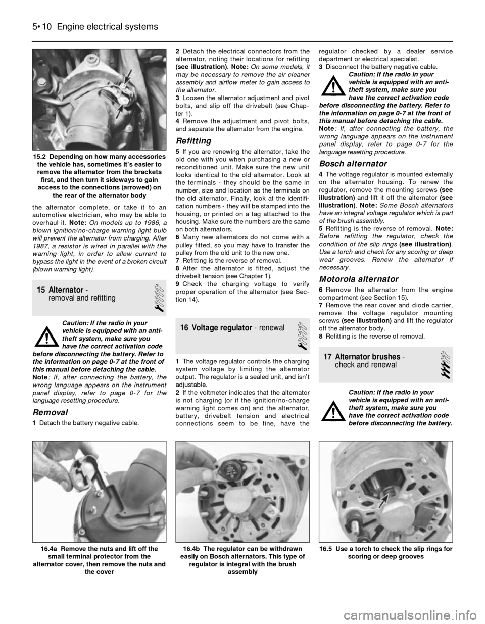
1Detach the battery negative cable.2Detach the electrical connectors from the
alternator, noting their locations for refitting
(see illustration). Note: On some models, it
may be necessary to remove the air cleaner
assembly and airflow meter to gain access to
the alternator.
3Loosen the alternator adjustment and pivot
bolts, and slip off the drivebelt (see Chap-
ter 1).
4Remove the adjustment and pivot bolts,
and separate the alternator from the engine.
Refitting
5If you are renewing the alternator, take the
old one with you when purchasing a new or
reconditioned unit. Make sure the new unit
looks identical to the old alternator. Look at
the terminals - they should be the same in
number, size and location as the terminals on
the old alternator. Finally, look at the identifi-
cation numbers - they will be stamped into the
housing, or printed on a tag attached to the
housing. Make sure the numbers are the same
on both alternators.
6Many new alternators do not come with a
pulley fitted, so you may have to transfer the
pulley from the old unit to the new one.
7Refitting is the reverse of removal.
8After the alternator is fitted, adjust the
drivebelt tension (see Chapter 1).
9Check the charging voltage to verify
proper operation of the alternator (see Sec-
tion 14).
16 Voltage regulator- renewal
1
1The voltage regulator controls the charging
system voltage by limiting the alternator
output. The regulator is a sealed unit, and isn’t
adjustable.
2If the voltmeter indicates that the alternator
is not charging (or if the ignition/no-charge
warning light comes on) and the alternator,
battery, drivebelt tension and electrical
connections seem to be fine, have theregulator checked by a dealer service
department or electrical specialist.
3Disconnect the battery negative cable.
Caution: If the radio in your
vehicle is equipped with an anti-
theft system, make sure you
have the correct activation code
before disconnecting the battery. Refer to
the information on page 0-7 at the front of
this manual before detaching the cable.
Note: If, after connecting the battery, the
wrong language appears on the instrument
panel display, refer to page 0-7 for the
language resetting procedure.
Bosch alternator
4The voltage regulator is mounted externally
on the alternator housing. To renew the
regulator, remove the mounting screws (see
illustration)and lift it off the alternator (see
illustration). Note: Some Bosch alternators
have an integral voltage regulator which is part
of the brush assembly.
5Refitting is the reverse of removal. Note:
Before refitting the regulator, check the
condition of the slip rings(see illustration).
Use a torch and check for any scoring or deep
wear grooves. Renew the alternator if
necessary.
Motorola alternator
6Remove the alternator from the engine
compartment (see Section 15).
7Remove the rear cover and diode carrier,
remove the voltage regulator mounting
screws (see illustration)and lift the regulator
off the alternator body.
8Refitting is the reverse of removal.
17 Alternator brushes-
check and renewal
3
Caution: If the radio in your
vehicle is equipped with an anti-
theft system, make sure you
have the correct activation code
before disconnecting the battery.
5•10 Engine electrical systems
16.5 Use a torch to check the slip rings for
scoring or deep grooves16.4b The regulator can be withdrawn
easily on Bosch alternators. This type of
regulator is integral with the brush
assembly16.4a Remove the nuts and lift off the
small terminal protector from the
alternator cover, then remove the nuts and
the cover
15.2 Depending on how many accessories
the vehicle has, sometimes it’s easier to
remove the alternator from the brackets
first, and then turn it sideways to gain
access to the connections (arrowed) on
the rear of the alternator body
Page 121 of 228
Refer to the information on page 0-7 at the
front of this manual before detaching the
cable.
Note: If, after connecting the battery, the
wrong language appears on the instrument
panel display, refer to page 0-7 for the
language resetting procedure.
1Disconnect the battery negative cable.
Bosch alternator
2Remove the voltage regulator from the back
of the alternator (see Section 16).
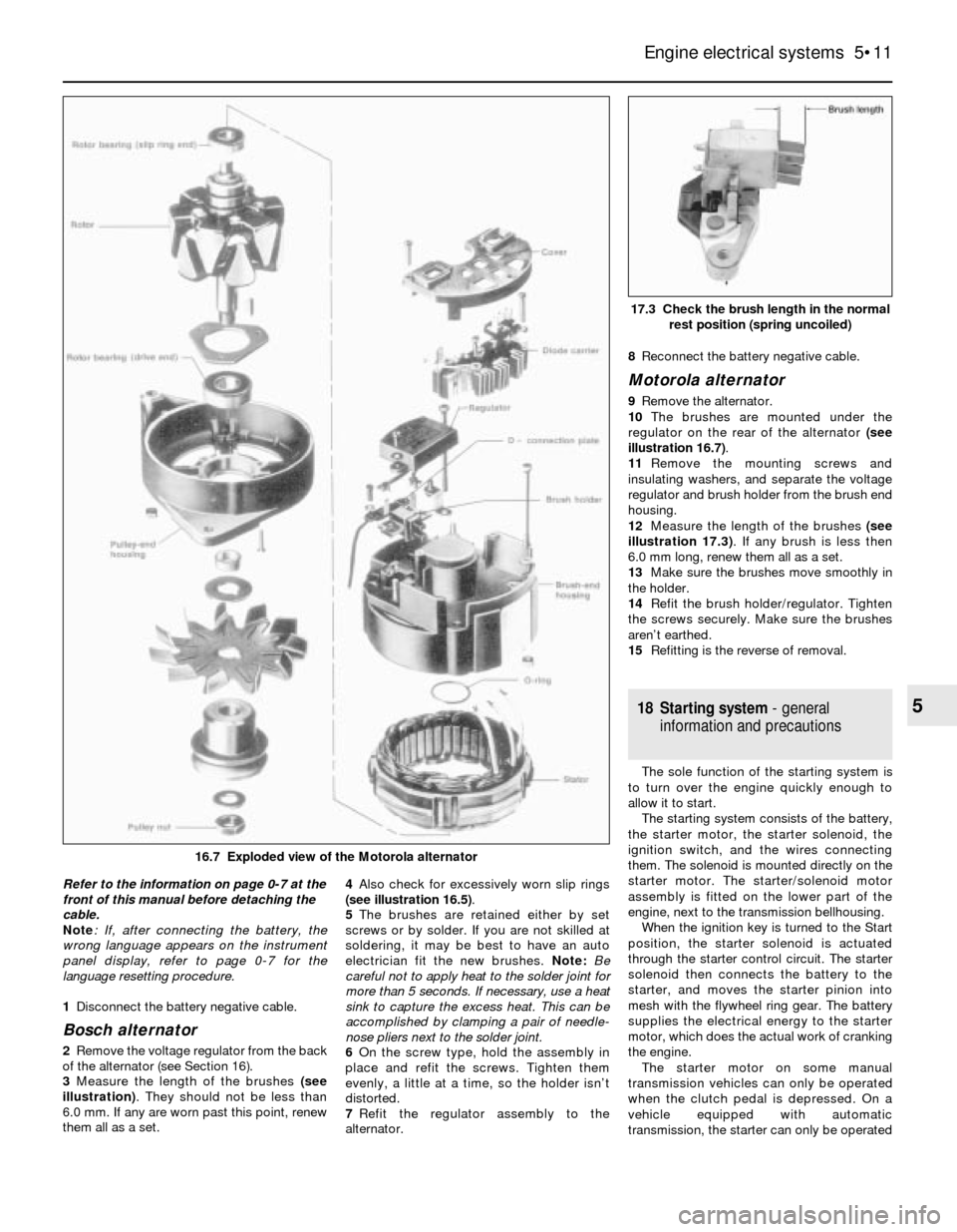
3Measure the length of the brushes (see
illustration). They should not be less than
6.0 mm. If any are worn past this point, renew
them all as a set. 4Also check for excessively worn slip rings
(see illustration 16.5).
5The brushes are retained either by set
screws or by solder. If you are not skilled at
soldering, it may be best to have an auto
electrician fit the new brushes. Note: Be
careful not to apply heat to the solder joint for
more than 5 seconds. If necessary, use a heat
sink to capture the excess heat. This can be
accomplished by clamping a pair of needle-
nose pliers next to the solder joint.
6On the screw type, hold the assembly in
place and refit the screws. Tighten them
evenly, a little at a time, so the holder isn’t
distorted.
7Refit the regulator assembly to the
alternator.8Reconnect the battery negative cable.
Motorola alternator
9Remove the alternator.
10The brushes are mounted under the
regulator on the rear of the alternator (see
illustration 16.7).
11Remove the mounting screws and
insulating washers, and separate the voltage
regulator and brush holder from the brush end
housing.
12Measure the length of the brushes (see
illustration 17.3). If any brush is less then
6.0 mm long, renew them all as a set.
13Make sure the brushes move smoothly in
the holder.
14Refit the brush holder/regulator. Tighten
the screws securely. Make sure the brushes
aren’t earthed.
15Refitting is the reverse of removal.
18 Starting system- general
information and precautions
The sole function of the starting system is
to turn over the engine quickly enough to
allow it to start.
The starting system consists of the battery,
the starter motor, the starter solenoid, the
ignition switch, and the wires connecting
them. The solenoid is mounted directly on the
starter motor. The starter/solenoid motor
assembly is fitted on the lower part of the
engine, next to the transmission bellhousing.
When the ignition key is turned to the Start
position, the starter solenoid is actuated
through the starter control circuit. The starter
solenoid then connects the battery to the
starter, and moves the starter pinion into
mesh with the flywheel ring gear. The battery
supplies the electrical energy to the starter
motor, which does the actual work of cranking
the engine.
The starter motor on some manual
transmission vehicles can only be operated
when the clutch pedal is depressed. On a
vehicle equipped with automatic
transmission, the starter can only be operated
Engine electrical systems 5•11
17.3 Check the brush length in the normal
rest position (spring uncoiled)
5
16.7 Exploded view of the Motorola alternator