Check panel BMW 3 SERIES 1985 E30 Owner's Guide
[x] Cancel search | Manufacturer: BMW, Model Year: 1985, Model line: 3 SERIES, Model: BMW 3 SERIES 1985 E30Pages: 228, PDF Size: 7.04 MB
Page 122 of 228
when the transmission selector lever is in Park
or Neutral.
Always detach the battery negative cable
before working on the starting system.
19 Starter motor-
in-vehicle check
2
Note:Before diagnosing starter problems,
make sure the battery is fully charged.
1If the starter motor does not turn at all when
the switch is operated, make sure that the
gear lever is in Neutral or Park (automatic
transmission) or, where applicable, that the
clutch pedal is depressed (manual
transmission).
2Make sure that the battery is charged, and
that all cables, both at the battery and starter
solenoid terminals, are clean and secure.
3If the starter motor spins but the engine is
not cranking, the overrun clutch in the starter
motor is slipping, and the starter motor must
be renewed.
4If, when the switch is actuated, the starter
motor does not operate at all but the solenoid
clicks, then the problem lies either in the
battery, the main solenoid contacts, or the
starter motor itself (or the engine is seized).
5If the solenoid plunger cannot be heard
when the switch is actuated, the battery is
faulty, the switch is defective, the fusible link
is burned-out (the circuit is open), or the
solenoid itself is defective.
6To check the solenoid, connect a jumper
lead between the battery (+) and the ignition
switch wire terminal (the small terminal) on the
solenoid. If the starter motor now operates,
the solenoid is OK and the problem is in the
ignition switch, starter inhibitor switch
(automatic transmission models), clutch
switch (some manual transmission models), or
the wiring.
7If the starter motor still does not operate,
remove the starter/solenoid assembly for
dismantling, testing and repair.
8If the starter motor cranks the engine at an
abnormally-slow speed, first make sure that
the battery is charged, and that all terminal
connections are tight. If the engine is partially-
seized, or has the wrong viscosity oil in it, it
will crank slowly.
9Run the engine until normal operating
temperature is reached, then disconnect the
coil HT lead from the distributor cap and earth
it on the engine.
10Connect a voltmeter positive lead to the
battery positive post, and connect the
negative lead to the negative post.11Crank the engine, and take the voltmeter
readings as soon as a steady figure is
indicated. Do not allow the starter motor to
turn for more than 10 seconds at a time. A
reading of 9 volts or more, with the starter
motor turning at normal cranking speed, is
normal. If the reading is 9 volts or more but
the cranking speed is slow, the solenoid
contacts are burned, there is a bad
connection, or the starter motor itself is faulty.
If the reading is less than 9 volts and the
cranking speed is slow, the starter motor is
faulty or the battery is responsible (defective
or discharged).
20 Starter motor-
removal and refitting
1
Note:If the starter motor is defective, it should
be renewed, or taken to an auto electrical
specialist for repair. Overhaul of the starter
motor is unlikely to be a practical proposition
for the home mechanic, even if spare parts are
available. However, the solenoid can be
renewed separately (see Section 21).
Removal
Caution: If the radio in your
vehicle is equipped with an anti-
theft system, make sure you
have the correct activation code
before disconnecting the battery. Refer to
the information on page 0-7 at the front of
this manual before detaching the cable.
Note: If, after connecting the battery, the
wrong language appears on the instrument
panel display, refer to page 0-7 for the
language resetting procedure.
1Detach the battery negative cable.
2Raise the vehicle and support it securely on
axle stands.
3Clearly label the wires from the terminals onthe starter motor and solenoid, then
disconnect them. Note: On some models, it
may be necessary to remove the air cleaner
(see Chapter 4), coolant expansion tank (see
Chapter 3) and the heater hoses to gain
access to the top of the starter. Carefully label
any hoses or components that need to be
removed from the engine compartment, to
avoid confusion when reassembling.
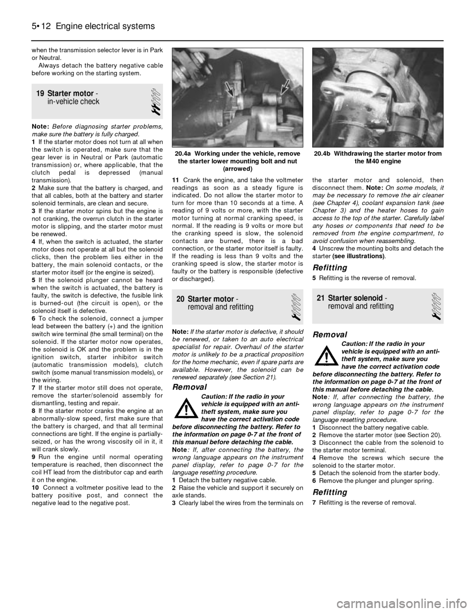
4Unscrew the mounting bolts and detach the
starter (see illustrations).
Refitting
5Refitting is the reverse of removal.
21 Starter solenoid-
removal and refitting
1
Removal
Caution: If the radio in your
vehicle is equipped with an anti-
theft system, make sure you
have the correct activation code
before disconnecting the battery. Refer to
the information on page 0-7 at the front of
this manual before detaching the cable.
Note: If, after connecting the battery, the
wrong language appears on the instrument
panel display, refer to page 0-7 for the
language resetting procedure.
1Disconnect the battery negative cable.
2Remove the starter motor (see Section 20).
3Disconnect the cable from the solenoid to
the starter motor terminal.
4Remove the screws which secure the
solenoid to the starter motor.
5Detach the solenoid from the starter body.
6Remove the plunger and plunger spring.
Refitting
7Refitting is the reverse of removal.
5•12 Engine electrical systems
20.4b Withdrawing the starter motor from
the M40 engine20.4a Working under the vehicle, remove
the starter lower mounting bolt and nut
(arrowed)
Page 123 of 228
6
Chapter 6
Engine management and emission control systems
Catalytic converter . . . . . . . . . . . . . . . . . . . . . . . . . . . . . . . . . . . . . . 7
Electronic Control Unit (ECU) - removal and refitting . . . . . . . . . . . . 3
Evaporative emissions control (EVAP) system . . . . . . . . . . . . . . . . . 6
Evaporative emissions control system inspection . . . See Chapter 1
General information . . . . . . . . . . . . . . . . . . . . . . . . . . . . . . . . . . . . . . 1Information sensors . . . . . . . . . . . . . . . . . . . . . . . . . . . . . . . . . . . . . . 4
Motronic engine management system self-diagnosis -
general information . . . . . . . . . . . . . . . . . . . . . . . . . . . . . . . . . . . . 2
Positive crankcase ventilation (PCV) system . . . . . . . . . . . . . . . . . . 5
6•1
Easy,suitable for
novice with little
experienceFairly easy,suitable
for beginner with
some experienceFairly difficult,
suitable for competent
DIY mechanic
Difficult,suitable for
experienced DIY
mechanicVery difficult,
suitable for expert
DIY or professional
Degrees of difficulty Contents
1 General information
To prevent pollution of the atmosphere
from incomplete combustion or evaporation
of the fuel, and to maintain good driveability
and fuel economy, a number of emission
control systems are used on these vehicles.
Not all of these systems are fitted to all
models, but they include the following:
Catalytic converter
Evaporative emission control (EVAP) system
Positive crankcase ventilation (PCV) system
Electronic engine management
The Sections in this Chapter include
general descriptions and checking
procedures within the scope of the home
mechanic, as well as component renewal
procedures (when possible) for each of the
systems listed above.
Before assuming that an emissions control
system is malfunctioning, check the fuel and
ignition systems carefully. The diagnosis of
some emission control devices requires
specialised tools, equipment and training. If
checking and servicing become too difficult,
or if a procedure is beyond your ability,
consult a dealer service department or other
specialist.This doesn’t mean, however, that emission
control systems are particularly difficult to
maintain and repair. You can quickly and
easily perform many checks, and do most of
the regular maintenance at home with
common tune-up and hand tools.
Pay close attention to any special
precautions outlined in this Chapter. It should
be noted that the illustrations of the various
systems may not exactly match the system
fitted on your vehicle because of
changes made by the manufacturer during
production.
2 Motronic engine management
system self-diagnosis-
general information
The Motronic engine management system
control unit (computer) has a built-in self-
diagnosis system, which detects malfunctions
in the system sensors and stores them as
fault codes in its memory. It is not possible
without dedicated test equipment to extract
these fault codes from the control unit.
However, the procedures given in Chapters 4
and 5 may be used to check individual
components and sensors of the Motronic
system. If this fails to pinpoint a fault, then the
vehicle should be taken to a BMW dealer, who
will have the necessary diagnostic
equipment to call up the fault codes from the
control unit. You will then have the
option to repair the fault yourself, or
alternatively have the fault repaired by the
BMW dealer.
3 Electronic control unit (ECU)
- removal and refitting
2
Removal
1The Electronic Control Unit (ECU) is located
either inside the passenger compartment
under the right-hand side of the facia panel on
3-Series models, or in the engine
compartment on the right-hand side on 5-
Series models (see Chapter 4).
2Disconnect the battery negative cable.
Caution: If the radio in your
vehicle is equipped with an anti-
theft system, make sure you
have the correct activation code
before disconnecting the battery. Refer to
the information on page 0-7 at the front of
this manual before detaching the cable.
Note: If, after connecting the battery, the
wrong language appears on the instrument
panel display, refer to page 0-7 for the
language resetting procedure.
3First remove the access cover on models
with the ECU on the right-hand side of the
engine compartment (see Chapter 4).
4If the ECU is located inside the vehicle,
remove the access cover on the right-hand side.
5Unplug the electrical connectors from the
ECU.
6Remove the retaining bolts from the ECU
bracket.
7Carefully remove the ECU. Note: Avoid static
electricity damage to the ECU by wearing rubber
gloves, and do not touch the connector pins.
Refitting
8Refitting is a reversal of removal.
The most frequent cause of
emission system problems is
simply a leaking vacuum hose
or loose wire, so always
check the hose and wiring connections
first.
Page 125 of 228
Check
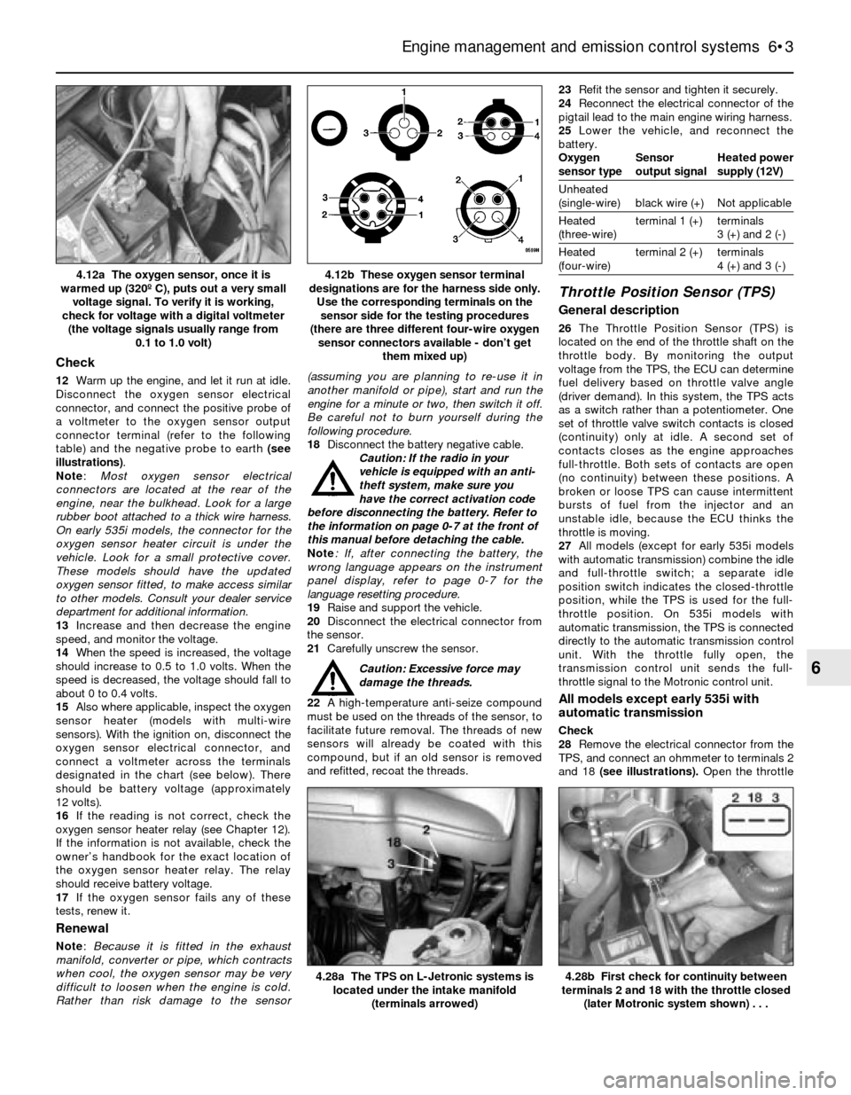
12Warm up the engine, and let it run at idle.
Disconnect the oxygen sensor electrical
connector, and connect the positive probe of
a voltmeter to the oxygen sensor output
connector terminal (refer to the following
table) and the negative probe to earth (see
illustrations).
Note:Most oxygen sensor electrical
connectors are located at the rear of the
engine, near the bulkhead. Look for a large
rubber boot attached to a thick wire harness.
On early 535i models, the connector for the
oxygen sensor heater circuit is under the
vehicle. Look for a small protective cover.
These models should have the updated
oxygen sensor fitted, to make access similar
to other models. Consult your dealer service
department for additional information.
13Increase and then decrease the engine
speed, and monitor the voltage.
14When the speed is increased, the voltage
should increase to 0.5 to 1.0 volts. When the
speed is decreased, the voltage should fall to
about 0 to 0.4 volts.
15Also where applicable, inspect the oxygen
sensor heater (models with multi-wire
sensors). With the ignition on, disconnect the
oxygen sensor electrical connector, and
connect a voltmeter across the terminals
designated in the chart (see below). There
should be battery voltage (approximately
12 volts).
16If the reading is not correct, check the
oxygen sensor heater relay (see Chapter 12).
If the information is not available, check the
owner’s handbook for the exact location of
the oxygen sensor heater relay. The relay
should receive battery voltage.
17If the oxygen sensor fails any of these
tests, renew it.
Renewal
Note: Because it is fitted in the exhaust
manifold, converter or pipe, which contracts
when cool, the oxygen sensor may be very
difficult to loosen when the engine is cold.
Rather than risk damage to the sensor(assuming you are planning to re-use it in
another manifold or pipe), start and run the
engine for a minute or two, then switch it off.
Be careful not to burn yourself during the
following procedure.
18Disconnect the battery negative cable.
Caution: If the radio in your
vehicle is equipped with an anti-
theft system, make sure you
have the correct activation code
before disconnecting the battery. Refer to
the information on page 0-7 at the front of
this manual before detaching the cable.
Note: If, after connecting the battery, the
wrong language appears on the instrument
panel display, refer to page 0-7 for the
language resetting procedure.
19Raise and support the vehicle.
20Disconnect the electrical connector from
the sensor.
21Carefully unscrew the sensor.
Caution: Excessive force may
damage the threads.
22A high-temperature anti-seize compound
must be used on the threads of the sensor, to
facilitate future removal. The threads of new
sensors will already be coated with this
compound, but if an old sensor is removed
and refitted, recoat the threads.23Refit the sensor and tighten it securely.
24Reconnect the electrical connector of the
pigtail lead to the main engine wiring harness.
25Lower the vehicle, and reconnect the
battery.
Oxygen Sensor Heated power
sensor type output signal supply (12V)
Unheated
(single-wire) black wire (+) Not applicable
Heated terminal 1 (+) terminals
(three-wire) 3 (+) and 2 (-)
Heated terminal 2 (+) terminals
(four-wire) 4 (+) and 3 (-)
Throttle Position Sensor (TPS)
General description
26The Throttle Position Sensor (TPS) is
located on the end of the throttle shaft on the
throttle body. By monitoring the output
voltage from the TPS, the ECU can determine
fuel delivery based on throttle valve angle
(driver demand). In this system, the TPS acts
as a switch rather than a potentiometer. One
set of throttle valve switch contacts is closed
(continuity) only at idle. A second set of
contacts closes as the engine approaches
full-throttle. Both sets of contacts are open
(no continuity) between these positions. A
broken or loose TPS can cause intermittent
bursts of fuel from the injector and an
unstable idle, because the ECU thinks the
throttle is moving.
27All models (except for early 535i models
with automatic transmission) combine the idle
and full-throttle switch; a separate idle
position switch indicates the closed-throttle
position, while the TPS is used for the full-
throttle position. On 535i models with
automatic transmission, the TPS is connected
directly to the automatic transmission control
unit. With the throttle fully open, the
transmission control unit sends the full-
throttle signal to the Motronic control unit.
All models except early 535i with
automatic transmission
Check
28Remove the electrical connector from the
TPS, and connect an ohmmeter to terminals 2
and 18 (see illustrations). Open the throttle
Engine management and emission control systems 6•3
4.12b These oxygen sensor terminal
designations are for the harness side only.
Use the corresponding terminals on the
sensor side for the testing procedures
(there are three different four-wire oxygen
sensor connectors available - don’t get
them mixed up)4.12a The oxygen sensor, once it is
warmed up (320º C), puts out a very small
voltage signal. To verify it is working,
check for voltage with a digital voltmeter
(the voltage signals usually range from
0.1 to 1.0 volt)
4.28b First check for continuity between
terminals 2 and 18 with the throttle closed
(later Motronic system shown) . . .4.28a The TPS on L-Jetronic systems is
located under the intake manifold
(terminals arrowed)
6
Page 130 of 228
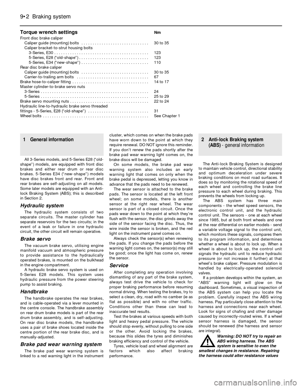
Torque wrench settingsNm
Front disc brake caliper
Caliper guide (mounting) bolts . . . . . . . . . . . . . . . . . . . . . . . . . . . . . . 30 to 35
Caliper bracket-to-strut housing bolts
3-Series, E30 . . . . . . . . . . . . . . . . . . . . . . . . . . . . . . . . . . . . . . . . . . 123
5-Series, E28 (“old-shape”) . . . . . . . . . . . . . . . . . . . . . . . . . . . . . . . 123
5-Series, E34 (“new-shape”) . . . . . . . . . . . . . . . . . . . . . . . . . . . . . . 110
Rear disc brake caliper
Caliper guide (mounting) bolts . . . . . . . . . . . . . . . . . . . . . . . . . . . . . . 30 to 35
Carrier-to-trailing arm bolts . . . . . . . . . . . . . . . . . . . . . . . . . . . . . . . . 67
Brake hose-to-caliper fitting . . . . . . . . . . . . . . . . . . . . . . . . . . . . . . . . . . 14 to 17
Master cylinder-to-brake servo nuts
3-Series . . . . . . . . . . . . . . . . . . . . . . . . . . . . . . . . . . . . . . . . . . . . . . . . 24
5-Series . . . . . . . . . . . . . . . . . . . . . . . . . . . . . . . . . . . . . . . . . . . . . . . . 25 to 29
Brake servo mounting nuts . . . . . . . . . . . . . . . . . . . . . . . . . . . . . . . . . . . 22 to 24
Hydraulic line-to-hydraulic brake servo threaded
fittings - 5-Series, E28 (“old-shape”) . . . . . . . . . . . . . . . . . . . . . . . . . . . 31
Wheel bolts . . . . . . . . . . . . . . . . . . . . . . . . . . . . . . . . . . . . . . . . . . . . . . . See Chapter 1
9•2 Braking system
1 General information
All 3-Series models, and 5-Series E28 (“old-
shape”) models, are equipped with front disc
brakes and either rear drum or rear disc
brakes. 5-Series E34 (“new-shape”) models
have disc brakes front and rear. Front and
rear brakes are self-adjusting on all models.
Some later models are equipped with an Anti-
lock Braking System (ABS); this is described
in Section 2.
Hydraulic system
The hydraulic system consists of two
separate circuits. The master cylinder has
separate reservoirs for the two circuits; in the
event of a leak or failure in one hydraulic
circuit, the other circuit will remain operative.
Brake servo
The vacuum brake servo, utilising engine
manifold vacuum and atmospheric pressure
to provide assistance to the hydraulically
operated brakes, is mounted on the bulkhead
in the engine compartment.
A hydraulic brake servo system is used on
5-Series E28 models. This system uses
hydraulic pressure from the power steering
pump to assist braking.
Handbrake
The handbrake operates the rear brakes,
and is cable-operated via a lever mounted in
the centre console. The handbrake assembly
on rear drum brake models is part of the rear
drum brake assembly, and is self-adjusting.
On rear disc brake models, the handbrake
uses a pair of brake shoes located inside the
centre portion of the rear brake disc, and is
manually-adjusted.
Brake pad wear warning system
The brake pad wear warning system is
linked to a red warning light in the instrumentcluster, which comes on when the brake pads
have worn down to the point at which they
require renewal. DO NOT ignore this reminder.
If you don’t renew the pads shortly after the
brake pad wear warning light comes on, the
brake discs will be damaged.
On some models, the brake pad wear
warning system also includes an early
warning light that comes on only when the
brake pedal is depressed, letting you know in
advance that the pads need to be renewed.
The wear sensor is attached to the brake
pads. The sensor is located at the left front
wheel; on some models, there is another
sensor at the right rear wheel. The wear
sensor is part of a closed circuit. Once the
pads wear down to the point at which they’re
flush with the sensor, the disc grinds away the
side of the sensor facing the disc. Thus, the
wire inside the sensor is broken, and the red
light on the instrument panel comes on.
Always check the sensor(s) when renewing
the pads. If you change the pads before the
warning light comes on, the sensor(s) may still
be good; once the light has come on, renew
the sensor.
Service
After completing any operation involving
dismantling of any part of the brake system,
always test drive the vehicle to check for
proper braking performance before resuming
normal driving. When testing the brakes, try to
select a clean, dry, road with no camber (ie as
flat as possible) and with no other traffic.
Conditions other than these can lead to
inaccurate test results.
Test the brakes at various speeds with both
light and heavy pedal pressure. The vehicle
should stop evenly, without pulling to one side
or the other. Avoid locking the brakes,
because this slides the tyres and diminishes
braking efficiency and control of the vehicle.
Tyres, vehicle load and wheel alignment are
factors which also affect braking
performance.
2 Anti-lock Braking system
(ABS)- general information
The Anti-lock Braking System is designed
to maintain vehicle control, directional stability
and optimum deceleration under severe
braking conditions on most road surfaces. It
does so by monitoring the rotational speed of
each wheel and controlling the brake line
pressure to each wheel during braking. This
prevents the wheels from locking up.
The ABS system has three main
components - the wheel speed sensors, the
electronic control unit, and the hydraulic
control unit. The sensors - one at each wheel
since 1985, but at both front wheels and one
at the rear differential on earlier models - send
a variable voltage signal to the control unit,
which monitors these signals, compares them
to its program information, and determines
whether a wheel is about to lock up. When a
wheel is about to lock up, the control unit
signals the hydraulic unit to reduce hydraulic
pressure (or not increase it further) at that
wheel’s brake caliper. Pressure modulation is
handled by electrically-operated solenoid
valves.
If a problem develops within the system, an
“ABS” warning light will glow on the
dashboard. Sometimes, a visual inspection of
the ABS system can help you locate the
problem. Carefully inspect the ABS wiring
harness. Pay particularly close attention to the
harness and connections near each wheel.
Look for signs of chafing and other damage
caused by incorrectly-routed wires. If a wheel
sensor harness is damaged, the sensor
should be renewed (the harness and sensor
are integral).
Warning: DO NOT try to repair an
ABS wiring harness. The ABS
system is sensitive to even the
smallest changes in resistance. Repairing
the harness could alter resistance values
Page 138 of 228
expel the air from the master cylinder. A large
Phillips screwdriver can be used to push on
the piston assembly.
11To prevent air from being drawn back into
the master cylinder, the plug must be refitted
and tightened down before releasing the
pressure on the piston assembly.
12Repeat the procedure until brake fluid free
of air bubbles is expelled from the brake line
outlet hole. Repeat the procedure with the
other outlet hole and plug. Be sure to keep the
master cylinder reservoir filled with brake
fluid, to prevent the introduction of air into the
system.
13High pressure is not involved in the bench
bleeding procedure, so the plugs described
above need not be refitted each time the
piston is released, if wished. Instead, before
releasing the piston, simply put your finger
tightly over the hole to keep air from being
drawn back into the master cylinder. Wait
several seconds for brake fluid to be drawn
from the reservoir into the piston bore, then
depress the piston again, removing your
finger as brake fluid is expelled. Be sure to put
your finger back over the hole each time
before releasing the piston, and when the
bleeding procedure is complete for that outlet,
refit the plug and tighten it up before going on
to the other port.
Refitting
14Refit the master cylinder (together with a
new O-ring) over the studs on the brake servo,
and tighten the mounting nuts only finger-tight
at this time.
15Thread the brake line fittings into the
master cylinder. Since the master cylinder is
still a bit loose, it can be moved slightly in
order for the fittings to thread in easily. Do not
strip the threads as the fittings are tightened.
16Tighten the brake fittings securely, and
the mounting nuts to the torque listed in this
Chapter’s Specifications.
17Fill the master cylinder reservoir with fluid,
then bleed the master cylinder (only if the
cylinder has not already been bled) and the
brake system as described in Section 16.
18To bleed the cylinder on the vehicle, have
an assistant pump the brake pedal severaltimes and then hold the pedal to the floor.
Loosen the fitting nut to allow air and fluid to
escape, then tighten the nut. Repeat this
procedure on both fittings until the fluid is
clear of air bubbles. Test the operation of the
brake system carefully before returning the
vehicle to normal service.
8 Brake vacuum servo-
check, removal and refitting
3
Operating check
1Depress the brake pedal several times with
the engine off, until there is no change in the
pedal travel.
2Depress and hold the pedal, then start the
engine. If the pedal goes down slightly,
operation is normal.
Airtightness check
3Start the engine, and turn it off after one or
two minutes. Depress the brake pedal several
times slowly. If the pedal goes down further
the first time but gradually rises after the
second or third depression, the servo is
airtight.
4Depress the brake pedal while the engine is
running, then stop the engine with the pedal
depressed. If there is no change in the pedal
travel after holding the pedal for 30 seconds,
the servo is airtight.
Removal and refitting
5Dismantling the vacuum servo requires
special tools, and cannot be performed by the
home mechanic. If a problem develops, it is
recommended that a new unit be fitted.
6Remove the master cylinder as described in
Section 7.
7Disconnect the vacuum hose from the
brake servo.
8Working in the passenger compartment,
remove the glovebox and lower left-hand trim
panels.
9Remove the clip and clevis pin to
disconnect the pushrod from the cross-shaft
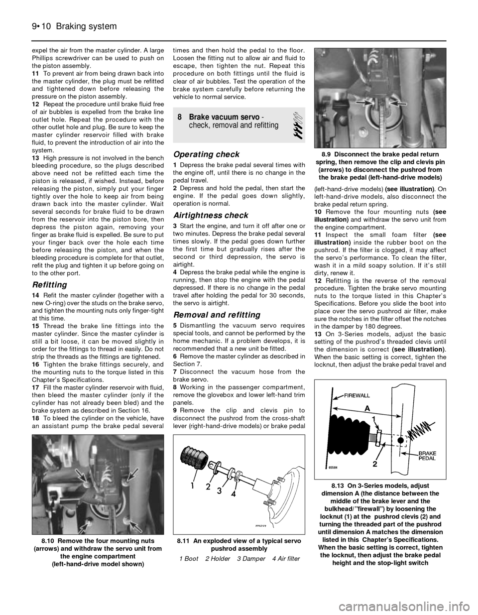
lever (right-hand-drive models) or brake pedal(left-hand-drive models) (see illustration). On
left-hand-drive models, also disconnect the
brake pedal return spring.
10Remove the four mounting nuts (see
illustration)and withdraw the servo unit from
the engine compartment.
11Inspect the small foam filter (see
illustration)inside the rubber boot on the
pushrod. If the filter is clogged, it may affect
the servo’s performance. To clean the filter,
wash it in a mild soapy solution. If it’s still
dirty, renew it.
12Refitting is the reverse of the removal
procedure. Tighten the brake servo mounting
nuts to the torque listed in this Chapter’s
Specifications. Before you slide the boot into
place over the servo pushrod air filter, make
sure the notches in the filter offset the notches
in the damper by 180 degrees.
13On 3-Series models, adjust the basic
setting of the pushrod’s threaded clevis until
the dimension is correct (see illustration).
When the basic setting is correct, tighten the
locknut, then adjust the brake pedal travel and
9•10 Braking system
8.13 On 3-Series models, adjust
dimension A (the distance between the
middle of the brake lever and the
bulkhead/”firewall”) by loosening the
locknut (1) at the pushrod clevis (2) and
turning the threaded part of the pushrod
until dimension A matches the dimension
listed in this Chapter’s Specifications.
When the basic setting is correct, tighten
the locknut, then adjust the brake pedal
height and the stop-light switch
8.11 An exploded view of a typical servo
pushrod assembly
1 Boot 2 Holder 3 Damper 4 Air filter8.10 Remove the four mounting nuts
(arrows) and withdraw the servo unit from
the engine compartment
(left-hand-drive model shown)
8.9 Disconnect the brake pedal return
spring, then remove the clip and clevis pin
(arrows) to disconnect the pushrod from
the brake pedal (left-hand-drive models)
Page 158 of 228
Refitting
7Refitting is the reverse of removal. Tighten
the nuts and bolts securely. Adjust the
drivebelt tension (see Chapter 1).
8Top-up the fluid level in the reservoir (see
Chapter 1) and bleed the system (see Sec-
tion 23).
23 Power steering system-
bleeding
1
1To bleed the power steering system, begin
by checking the power steering fluid level and
adding fluid if necessary (see Chapter 1).
2Raise and support the front of the vehicle
on axle stands.
3Turn the steering wheel from lock-to-lock
several times. Recheck the fluid level and top
up if necessary.
4Start the engine and run it at 1000 rpm or
less. Turn the steering wheel from lock-to-
lock again (three or four times) and recheck
the fluid level one more time. Note:On 5-Series E28 (“old-shape”) models, pump the
brake pedal five or six times before turning the
steering wheel. Once the fluid level remains
constant, continue turning the wheel back and
forth until no more bubbles appear in the fluid
in the reservoir.
5Lower the vehicle to the ground. Run the
engine and again turn the wheels from lock-
to-lock several more times. Recheck the fluid
level. Position the wheels straight-ahead.24 Steering wheel-
removal and refitting
1
Warning: If the vehicle is
equipped with an airbag, do not
attempt this procedure. Have it
performed by a dealer service
department or other qualified specialist, as
there is a risk of injury if the airbag is
accidentally triggered.
Caution: If the radio in your
vehicle is equipped with an anti-
theft system, make sure you have
the correct activation code
before disconnecting the battery.
Note: If, after connecting the battery, the
wrong language appears on the instrument
panel display, refer to page 0-7 for the
language resetting procedure.
Removal
1Disconnect the battery negative cable.
2Using a small screwdriver, prise off the
BMW emblem in the centre of the steering
wheel.
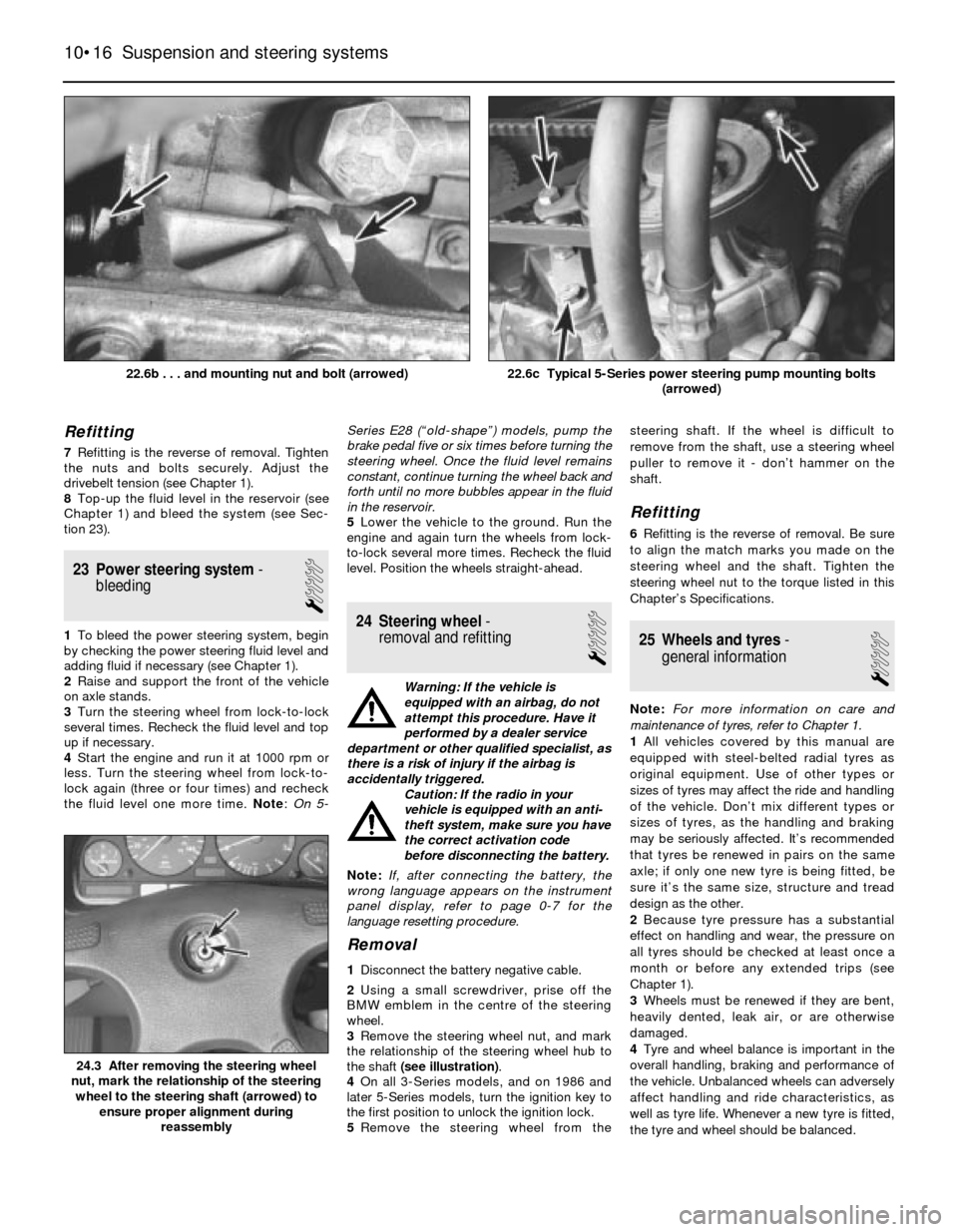
3Remove the steering wheel nut, and mark
the relationship of the steering wheel hub to
the shaft (see illustration).
4On all 3-Series models, and on 1986 and
later 5-Series models, turn the ignition key to
the first position to unlock the ignition lock.
5Remove the steering wheel from thesteering shaft. If the wheel is difficult to
remove from the shaft, use a steering wheel
puller to remove it - don’t hammer on the
shaft.
Refitting
6Refitting is the reverse of removal. Be sure
to align the match marks you made on the
steering wheel and the shaft. Tighten the
steering wheel nut to the torque listed in this
Chapter’s Specifications.
25 Wheels and tyres-
general information
1
Note:For more information on care and
maintenance of tyres, refer to Chapter 1.
1All vehicles covered by this manual are
equipped with steel-belted radial tyres as
original equipment. Use of other types or
sizes of tyres may affect the ride and handling
of the vehicle. Don’t mix different types or
sizes of tyres, as the handling and braking
may be seriously affected. It’s recommended
that tyres be renewed in pairs on the same
axle; if only one new tyre is being fitted, be
sure it’s the same size, structure and tread
design as the other.
2Because tyre pressure has a substantial
effect on handling and wear, the pressure on
all tyres should be checked at least once a
month or before any extended trips (see
Chapter 1).
3Wheels must be renewed if they are bent,
heavily dented, leak air, or are otherwise
damaged.
4Tyre and wheel balance is important in the
overall handling, braking and performance of
the vehicle. Unbalanced wheels can adversely
affect handling and ride characteristics, as
well as tyre life. Whenever a new tyre is fitted,
the tyre and wheel should be balanced.
10•16 Suspension and steering systems
24.3 After removing the steering wheel
nut, mark the relationship of the steering
wheel to the steering shaft (arrowed) to
ensure proper alignment during
reassembly
22.6c Typical 5-Series power steering pump mounting bolts
(arrowed)22.6b . . . and mounting nut and bolt (arrowed)
Page 160 of 228
11
1 General information
These models feature an all-steel welded
construction, where the floorpan and body
components are welded together and
attached to separate front and rear subframe
assemblies. Certain components are
particularly vulnerable to accident damage,
and can be unbolted and repaired or renewed.
Among these parts are the body mouldings,
bumpers, bonnet, doors, tailgate, and all
glass.
Only general body maintenance procedures
and body panel repair procedures within the
scope of the do-it-yourselfer are included in
this Chapter.
2 Bodywork and underframe-
maintenance
1
The general condition of a vehicle’s
bodywork is the one thing that significantly
affects its value. Maintenance is easy, but
needs to be regular. Neglect, particularly after
minor damage, can lead quickly to further
deterioration and costly repair bills. It is
important also to keep watch on those parts
of the vehicle not immediately visible, for
instance the underside, inside all the wheelarches, and the lower part of the engine
compartment.
The basic maintenance routine for the
bodywork is washing - preferably with a lot of
water, from a hose. This will remove all the
loose solids which may have stuck to the
vehicle. It is important to flush these off in
such a way as to prevent grit from scratching
the finish. The wheel arches and underframe
need washing in the same way, to remove any
accumulated mud, which will retain moisture
and tend to encourage rust. Paradoxically
enough, the best time to clean the underframe
and wheel arches is in wet weather, when the
mud is thoroughly wet and soft. In very wet
weather, the underframe is usually cleaned of
large accumulations automatically, and this is
a good time for inspection.
Periodically, except on vehicles with a wax-
based underbody protective coating, it is a
good idea to have the whole of the
underframe of the vehicle steam-cleaned,
engine compartment included, so that a
thorough inspection can be carried out to see
what minor repairs and renovations are
necessary. Steam-cleaning is available at
many garages, and is necessary for the
removal of the accumulation of oily grime,
which sometimes is allowed to become thick
in certain areas. If steam-cleaning facilities are
not available, there are some excellent grease
solvents available which can be brush-
applied; the dirt can then be simply hosed off.
Note that these methods should not be usedon vehicles with wax-based underbody
protective coating, or the coating will be
removed. Such vehicles should be inspected
annually, preferably just prior to Winter, when
the underbody should be washed down, and
any damage to the wax coating repaired.
Ideally, a completely fresh coat should be
applied. It would also be worth considering
the use of such wax-based protection for
injection into door panels, sills, box sections,
etc, as an additional safeguard against rust
damage, where such protection is not
provided by the vehicle manufacturer.
After washing paintwork, wipe off with a
chamois leather to give an unspotted clear
finish. A coat of clear protective wax polish will
give added protection against chemical
pollutants in the air. If the paintwork sheen has
dulled or oxidised, use a cleaner/polisher
combination to restore the brilliance of the
shine. This requires a little effort, but such
dulling is usually caused because regular
washing has been neglected. Care needs to be
taken with metallic paintwork, as special non-
abrasive cleaner/polisher is required to avoid
damage to the finish. Always check that the
door and ventilator opening drain holes and
pipes are completely clear, so that water can
be drained out. Brightwork should be treated in
the same way as paintwork. Windscreens and
windows can be kept clear of the smeary film
which often appears, by the use of proprietary
glass cleaner. Never use any form of wax or
other body or chromium polish on glass.
Chapter 11 Bodywork and fittings
Bodywork and underframe - maintenance . . . . . . . . . . . . . . . . . . . . 2
Bodywork repair - major damage . . . . . . . . . . . . . . . . . . . . . . . . . . . 6
Bodywork repair - minor damage . . . . . . . . . . . . . . . . . . . . . . . . . . . 5
Bonnet - removal, refitting and adjustment . . . . . . . . . . . . . . . . . . . . 10
Boot lid/tailgate - removal, refitting and adjustment . . . . . . . . . . . . . 14
Bumpers - removal and refitting . . . . . . . . . . . . . . . . . . . . . . . . . . . . 11
Door - removal, refitting and adjustment . . . . . . . . . . . . . . . . . . . . . 13
Door trim panel - removal and refitting . . . . . . . . . . . . . . . . . . . . . . . 12
Door window glass - removal and refitting . . . . . . . . . . . . . . . . . . . . 16
Door window regulator - removal and refitting . . . . . . . . . . . . . . . . . 17
Exterior mirror - removal and refitting . . . . . . . . . . . . . . . . . . . . . . . . 18Fixed glass - renewal . . . . . . . . . . . . . . . . . . . . . . . . . . . . . . . . . . . . 8
General information . . . . . . . . . . . . . . . . . . . . . . . . . . . . . . . . . . . . . . 1
Hinges and locks - maintenance . . . . . . . . . . . . . . . . . . . . . . . . . . . . 7
Interior trim - maintenance . . . . . . . . . . . . . . . . . . . . . . . . . . . . . . . . 3
Latch, lock cylinder and handles - removal, refitting and
adjustment . . . . . . . . . . . . . . . . . . . . . . . . . . . . . . . . . . . . . . . . . . . 15
Radiator grille - removal and refitting . . . . . . . . . . . . . . . . . . . . . . . . 9
Seat belt check . . . . . . . . . . . . . . . . . . . . . . . . . . . . . . . . . . . . . . . . . 21
Seats - removal and refitting . . . . . . . . . . . . . . . . . . . . . . . . . . . . . . . 20
Steering column shrouds - removal and refitting . . . . . . . . . . . . . . . 19
Upholstery and carpets - maintenance . . . . . . . . . . . . . . . . . . . . . . . 4
11•1
Easy,suitable for
novice with little
experienceFairly easy,suitable
for beginner with
some experienceFairly difficult,
suitable for competent
DIY mechanic
Difficult,suitable for
experienced DIY
mechanicVery difficult,
suitable for expert
DIY or professional
Degrees of difficulty Contents
Page 162 of 228
it to the approximate size and shape required,
then pull off the backing paper (if used) and
stick the tape over the hole; it can be
overlapped if the thickness of one piece is
insufficient. Burnish down the edges of the
tape with the handle of a screwdriver or
similar, to ensure that the tape is securely
attached to the metal underneath.
Bodywork repairs - filling and
respraying
Before using this Section, see the Sections
on dent, deep scratch, rust holes and gash
repairs.
Many types of bodyfiller are available, but
generally speaking, those proprietary kits
which contain a tin of filler paste and a tube of
resin hardener are best for this type of repair. A
wide, flexible plastic or nylon applicator will be
found invaluable for imparting a smooth and
well-contoured finish to the surface of the filler.
Mix up a little filler on a clean piece of card
or board - measure the hardener carefully
(follow the maker’s instructions on the pack),
otherwise the filler will set too rapidly or too
slowly. Using the applicator, apply the filler
paste to the prepared area; draw the
applicator across the surface of the filler to
achieve the correct contour and to level the
surface. As soon as a contour that
approximates to the correct one is achieved,
stop working the paste - if you carry on too
long, the paste will become sticky and begin
to “pick-up” on the applicator. Continue to
add thin layers of filler paste at 20-minute
intervals, until the level of the filler is just
proud of the surrounding bodywork.
Once the filler has hardened, the excess
can be removed using a metal plane or file.
From then on, progressively-finer grades of
abrasive paper should be used, starting with a
40-grade production paper, and finishing with
a 400-grade wet-and-dry paper. Always wrap
the abrasive paper around a flat rubber, cork,
or wooden block - otherwise the surface of
the filler will not be completely flat. During the
smoothing of the filler surface, the wet-and-
dry paper should be periodically rinsed in
water. This will ensure that a very smooth
finish is imparted to the filler at the final stage.
At this stage, the “dent” should be
surrounded by a ring of bare metal, which in
turn should be encircled by the finely
“feathered” edge of the good paintwork.
Rinse the repair area with clean water, until all
of the dust produced by the rubbing-down
operation has gone.
Spray the whole area with a light coat of
primer - this will show up any imperfections in
the surface of the filler. Repair these
imperfections with fresh filler paste or
bodystopper, and once more smooth the
surface with abrasive paper. Repeat this
spray-and-repair procedure until you are
satisfied that the surface of the filler, and the
feathered edge of the paintwork, are perfect.
Clean the repair area with clean water, and
allow to dry fully.The repair area is now ready for final
spraying. Paint spraying must be carried out
in a warm, dry, windless and dust-free
atmosphere. This condition can be created
artificially if you have access to a large indoor
working area, but if you are forced to work in
the open, you will have to pick your day very
carefully. If you are working indoors, dousing
the floor in the work area with water will help
to settle the dust which would otherwise be in
the atmosphere. If the repair area is confined
to one body panel, mask off the surrounding
panels; this will help to minimise the effects of
a slight mis-match in paint colours. Bodywork
fittings (eg chrome strips, door handles etc)
will also need to be masked off. Use genuine
masking tape, and several thicknesses of
newspaper, for the masking operations.
Before commencing to spray, agitate the
aerosol can thoroughly, then spray a test area
(an old tin, or similar) until the technique is
mastered. Cover the repair area with a thick
coat of primer; the thickness should be built
up using several thin layers of paint, rather
than one thick one. Using 400-grade wet-and-
dry paper, rub down the surface of the primer
until it is really smooth. While doing this, the
work area should be thoroughly doused with
water, and the wet-and-dry paper periodically
rinsed in water. Allow to dry before spraying
on more paint.
Spray on the top coat, again building up the
thickness by using several thin layers of paint.
Start spraying at one edge of the repair area,
and then, using a side-to-side motion, work
until the whole repair area and about 2 inches
of the surrounding original paintwork is
covered. Remove all masking material 10 to
15 minutes after spraying on the final coat of
paint.
Allow the new paint at least two weeks to
harden, then, using a paintwork renovator, or
a very fine cutting paste, blend the edges of
the paint into the existing paintwork. Finally,
apply wax polish.
Plastic components
With the use of more and more plastic body
components by the vehicle manufacturers (eg
bumpers. spoilers, and in some cases major
body panels), rectification of more serious
damage to such items has become a matter
of either entrusting repair work to a specialist
in this field, or renewing complete
components. Repair of such damage by the
DIY owner is not really feasible, owing to the
cost of the equipment and materials required
for effecting such repairs. The basic technique
involves making a groove along the line of the
crack in the plastic, using a rotary burr in a
power drill. The damaged part is then weldedback together, using a hot-air gun to heat up
and fuse a plastic filler rod into the groove.
Any excess plastic is then removed, and the
area rubbed down to a smooth finish. It is
important that a filler rod of the correct plastic
is used, as body components can be made of
a variety of different types (eg polycarbonate,
ABS, polypropylene).
Damage of a less serious nature (abrasions,
minor cracks etc) can be repaired by the DIY
owner using a two-part epoxy filler repair
material. Once mixed in equal proportions,
this is used in similar fashion to the bodywork
filler used on metal panels. The filler is usually
cured in twenty to thirty minutes, ready for
sanding and painting.
If the owner is renewing a complete
component himself, or if he has repaired it
with epoxy filler, he will be left with the
problem of finding a suitable paint for finishing
which is compatible with the type of plastic
used. At one time, the use of a universal paint
was not possible, owing to the complex range
of plastics encountered in body component
applications. Standard paints, generally
speaking, will not bond to plastic or rubber
satisfactorily. However, it is now possible to
obtain a plastic body parts finishing kit which
consists of a pre-primer treatment, a primer
and coloured top coat. Full instructions are
normally supplied with a kit, but basically, the
method of use is to first apply the pre-primer
to the component concerned, and allow it to
dry for up to 30 minutes. Then the primer is
applied, and left to dry for about an hour
before finally applying the special-coloured
top coat. The result is a correctly-coloured
component, where the paint will flex with the
plastic or rubber, a property that standard
paint does not normally possess.
6 Bodywork repair-
major damage
5
1Major damage must be repaired by a
qualified bodywork repair specialist, or
preferably by a BMW dealer. Specialised
equipment is required to do the job properly.
2If the damage is extensive, the bodyshell
must be checked for proper alignment, or the
vehicle’s handling characteristics may be
adversely affected and other components
may wear at an accelerated rate.
3Due to the fact that all of the major body
components (bonnet, wings, etc.) are
separate units, any seriously damaged
components should be replaced with new
ones rather than repaired.
Bodywork and fittings 11•3
11
If bodystopper is used, it can
be mixed with cellulose
thinners to form a really thin
paste which is ideal for filling
small holes
Sometimes bodywork
components can be found in
a scrapyard that specialises
in used vehicle components,
often at a considerable saving over the
cost of new parts.
Page 165 of 228
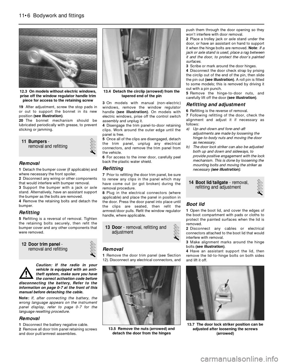
19After adjustment, screw the stop pads in
or out to support the bonnet in its new
position (see illustration).
20The bonnet mechanism should be
lubricated periodically with grease, to prevent
sticking or jamming.
11 Bumpers-
removal and refitting
1
Removal
1Detach the bumper cover (if applicable) and
where necessary the front spoiler.
2Disconnect any wiring or other components
that would interfere with bumper removal.
3Support the bumper with a jack or axle
stand. Alternatively, have an assistant support
the bumper as the bolts are removed.
4Remove the retaining bolts and detach the
bumper.
Refitting
5Refitting is a reversal of removal. Tighten
the retaining bolts securely, then refit the
bumper cover and any other components that
were removed.
12 Door trim panel-
removal and refitting
1
Caution: If the radio in your
vehicle is equipped with an anti-
theft system, make sure you have
the correct activation code before
disconnecting the battery, Refer to the
information on page 0-7 at the front of this
manual before detaching the cable.
Note: If, after connecting the battery, the
wrong language appears on the instrument
panel display, refer to page 0-7 for the
language resetting procedure.
Removal
1Disconnect the battery negative cable.
2Remove all door trim panel retaining screws
and door pull/armrest assemblies.3On models with manual (non-electric)
windows, remove the window regulator
handle (see illustration). On models with
electric windows, prise off the control switch
assembly and unplug it.
4Disengage the trim panel-to-door retaining
clips. Work around the outer edge until the
panel is free.
5Once all of the clips are disengaged, detach
the trim panel, unplug any electrical
connectors, and remove the trim panel from
the vehicle.
6For access to the inner door, carefully peel
back the plastic water shield.
Refitting
7Prior to refitting the door trim panel, be sure
to renew any clips in the panel which may
have come out (or got broken) during the
removal procedure.
8Plug in the electrical connectors (where
applicable) and place the panel in position in
the door. Press the door panel into place until
the clips are seated, then refit the
armrest/door pulls. Refit the window regulator
handle, where applicable.
13 Door- removal, refitting and
adjustment
1
Removal
1Remove the door trim panel (see Section
12). Disconnect any electrical connectors, andpush them through the door opening so they
won’t interfere with door removal.
2Place a trolley jack or axle stand under the
door, or have an assistant on hand to support
it when the hinge bolts are removed. Note: If a
jack or axle stand is used, place a rag between
it and the door, to protect the door’s painted
surfaces.
3Scribe or mark around the door hinges.
4Disconnect the door check strap by prising
the circlip out of the end of the pin, then slide
the pin out (see illustration). A roll pin is fitted
to some models; this is removed by driving it
out with a pin punch.
5Remove the hinge-to-door nuts, and
carefully lift off the door (see illustration).
Refitting and adjustment
6Refitting is the reverse of removal.
7Following refitting of the door, check the
alignment and adjust it if necessary as
follows:
a) Up-and-down and fore-and-aft
adjustments are made by loosening the
hinge-to-body nuts and moving the door
as necessary.
b) The door lock striker can also be adjusted
both up and down and sideways, to
provide positive engagement with the lock
mechanism. This is done by loosening the
mounting bolts and moving the striker as
necessary (see illustration).
14 Boot lid/tailgate- removal,
refitting and adjustment
1
Boot lid
1Open the boot lid, and cover the edges of
the boot compartment with pads or cloths to
protect the painted surfaces when the lid is
removed.
2Disconnect any cables or electrical
connectors attached to the boot lid that would
interfere with removal.
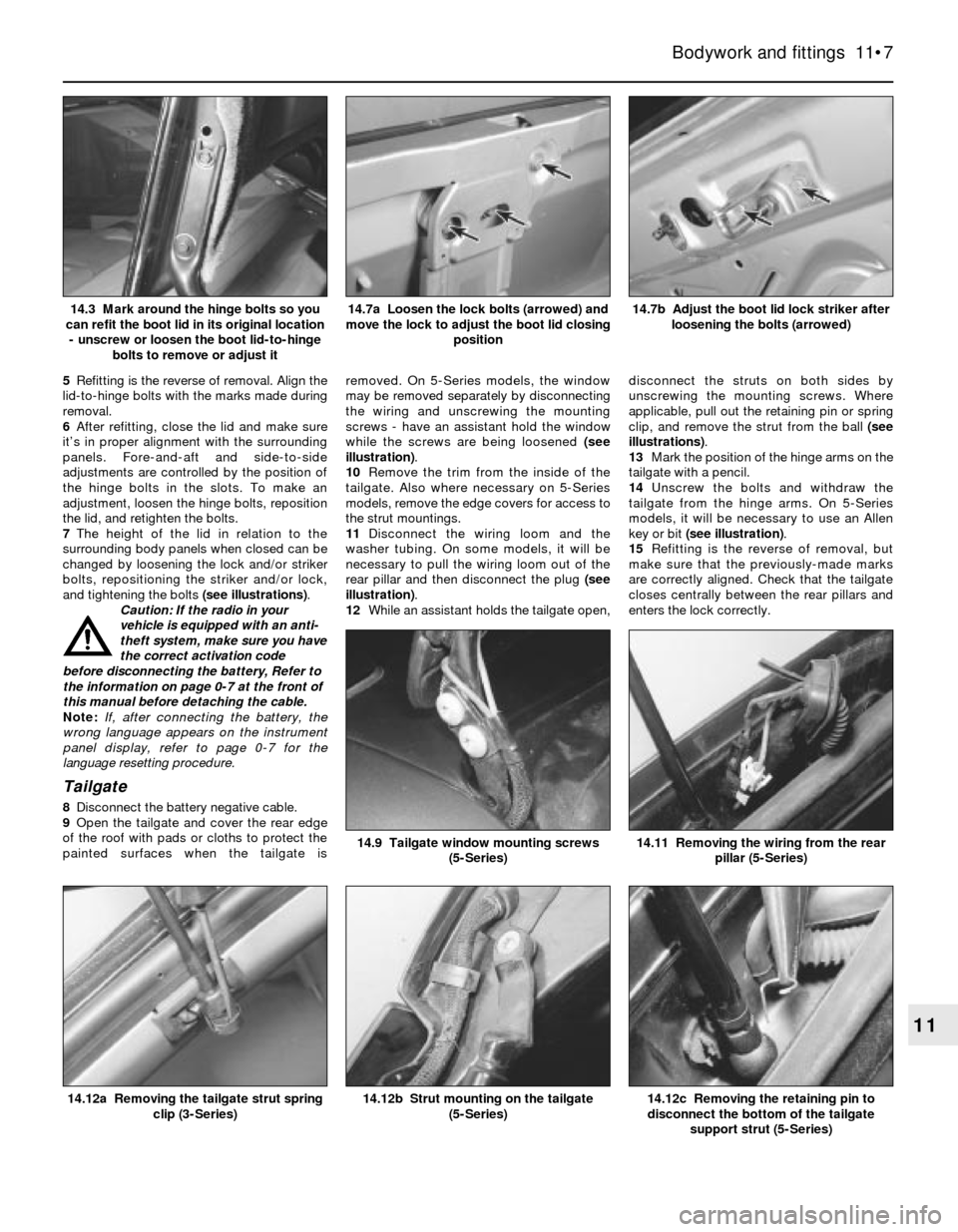
3Make alignment marks around the hinge
bolts (see illustration).
4Have an assistant support the lid, then
remove the lid-to-hinge bolts on both sides
and lift it off.
11•6 Bodywork and fittings
13.7 The door lock striker position can be
adjusted after loosening the screws
(arrowed)13.5 Remove the nuts (arrowed) and
detach the door from the hinges
13.4 Detach the circlip (arrowed) from the
tapered end of the pin12.3 On models without electric windows,
prise off the window regulator handle trim
piece for access to the retaining screw
Page 166 of 228
5Refitting is the reverse of removal. Align the
lid-to-hinge bolts with the marks made during
removal.
6After refitting, close the lid and make sure
it’s in proper alignment with the surrounding
panels. Fore-and-aft and side-to-side
adjustments are controlled by the position of
the hinge bolts in the slots. To make an
adjustment, loosen the hinge bolts, reposition
the lid, and retighten the bolts.
7The height of the lid in relation to the
surrounding body panels when closed can be
changed by loosening the lock and/or striker
bolts, repositioning the striker and/or lock,
and tightening the bolts (see illustrations).
Caution: If the radio in your
vehicle is equipped with an anti-
theft system, make sure you have
the correct activation code
before disconnecting the battery, Refer to
the information on page 0-7 at the front of
this manual before detaching the cable.
Note: If, after connecting the battery, the
wrong language appears on the instrument
panel display, refer to page 0-7 for the
language resetting procedure.
Tailgate
8Disconnect the battery negative cable.
9Open the tailgate and cover the rear edge
of the roof with pads or cloths to protect the
painted surfaces when the tailgate isremoved. On 5-Series models, the window
may be removed separately by disconnecting
the wiring and unscrewing the mounting
screws - have an assistant hold the window
while the screws are being loosened (see
illustration).
10Remove the trim from the inside of the
tailgate. Also where necessary on 5-Series
models, remove the edge covers for access to
the strut mountings.
11Disconnect the wiring loom and the
washer tubing. On some models, it will be
necessary to pull the wiring loom out of the
rear pillar and then disconnect the plug (see
illustration).
12While an assistant holds the tailgate open,disconnect the struts on both sides by
unscrewing the mounting screws. Where
applicable, pull out the retaining pin or spring
clip, and remove the strut from the ball (see
illustrations).
13Mark the position of the hinge arms on the
tailgate with a pencil.
14Unscrew the bolts and withdraw the
tailgate from the hinge arms. On 5-Series
models, it will be necessary to use an Allen
key or bit (see illustration).
15Refitting is the reverse of removal, but
make sure that the previously-made marks
are correctly aligned. Check that the tailgate
closes centrally between the rear pillars and
enters the lock correctly.
Bodywork and fittings 11•7
14.7b Adjust the boot lid lock striker after
loosening the bolts (arrowed)14.7a Loosen the lock bolts (arrowed) and
move the lock to adjust the boot lid closing
position14.3 Mark around the hinge bolts so you
can refit the boot lid in its original location
- unscrew or loosen the boot lid-to-hinge
bolts to remove or adjust it
14.12c Removing the retaining pin to
disconnect the bottom of the tailgate
support strut (5-Series)14.12b Strut mounting on the tailgate
(5-Series)14.12a Removing the tailgate strut spring
clip (3-Series)
14.11 Removing the wiring from the rear
pillar (5-Series)14.9 Tailgate window mounting screws
(5-Series)
11