check control BMW 3 SERIES 1985 E30 Owner's Guide
[x] Cancel search | Manufacturer: BMW, Model Year: 1985, Model line: 3 SERIES, Model: BMW 3 SERIES 1985 E30Pages: 228, PDF Size: 7.04 MB
Page 117 of 228
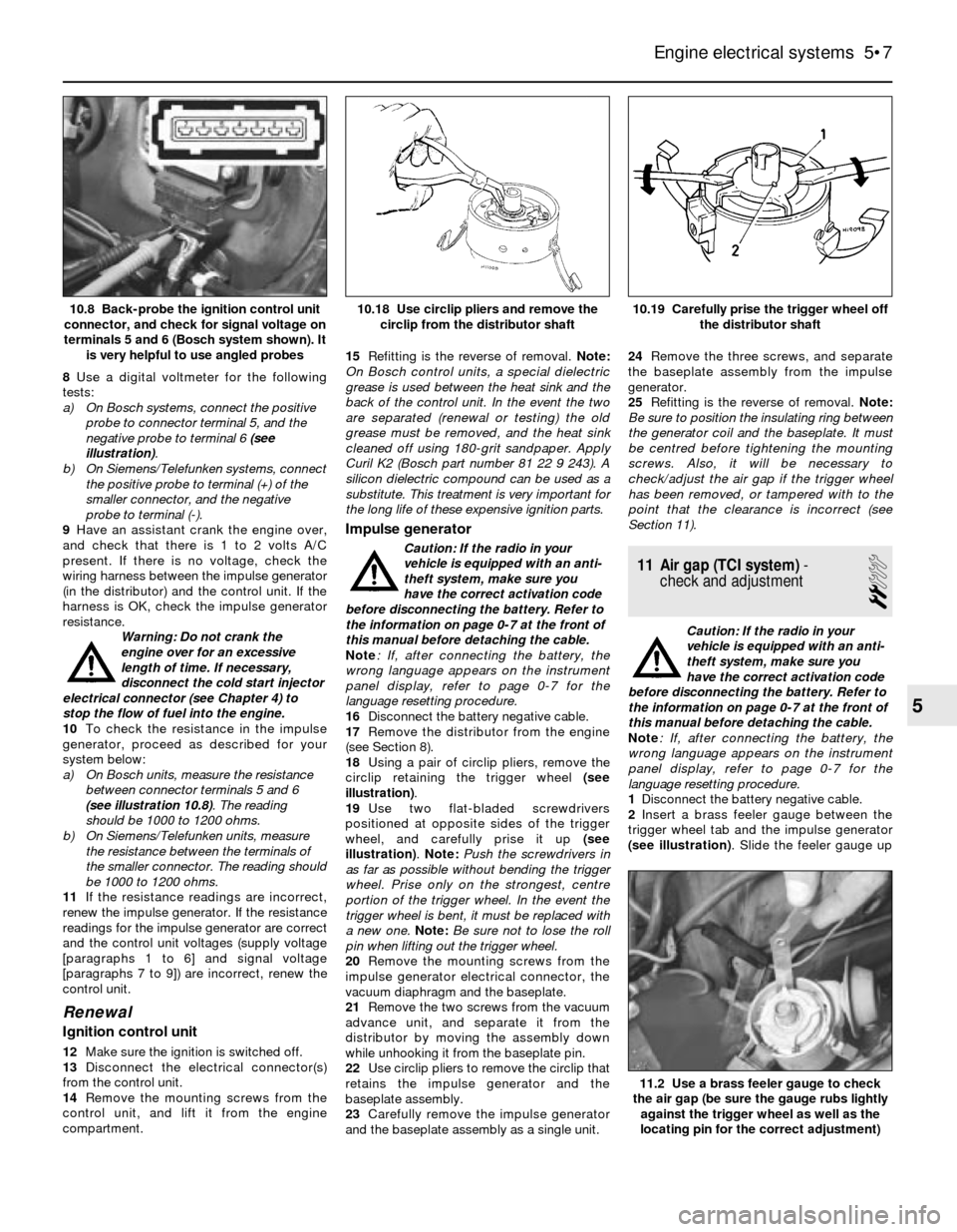
8Use a digital voltmeter for the following
tests:
a) On Bosch systems, connect the positive
probe to connector terminal 5, and the
negative probe to terminal 6 (see
illustration).
b) On Siemens/Telefunken systems, connect
the positive probe to terminal (+) of the
smaller connector, and the negative
probe to terminal (-).
9Have an assistant crank the engine over,
and check that there is 1 to 2 volts A/C
present. If there is no voltage, check the
wiring harness between the impulse generator
(in the distributor) and the control unit. If the
harness is OK, check the impulse generator
resistance.
Warning: Do not crank the
engine over for an excessive
length of time. If necessary,
disconnect the cold start injector
electrical connector (see Chapter 4) to
stop the flow of fuel into the engine.
10To check the resistance in the impulse
generator, proceed as described for your
system below:
a) On Bosch units, measure the resistance
between connector terminals 5 and 6
(see illustration 10.8). The reading
should be 1000 to 1200 ohms.
b) On Siemens/Telefunken units, measure
the resistance between the terminals of
the smaller connector. The reading should
be 1000 to 1200 ohms.
11If the resistance readings are incorrect,
renew the impulse generator. If the resistance
readings for the impulse generator are correct
and the control unit voltages (supply voltage
[paragraphs 1 to 6] and signal voltage
[paragraphs 7 to 9]) are incorrect, renew the
control unit.
Renewal
Ignition control unit
12Make sure the ignition is switched off.
13Disconnect the electrical connector(s)
from the control unit.
14Remove the mounting screws from the
control unit, and lift it from the engine
compartment.15Refitting is the reverse of removal. Note:
On Bosch control units, a special dielectric
grease is used between the heat sink and the
back of the control unit. In the event the two
are separated (renewal or testing) the old
grease must be removed, and the heat sink
cleaned off using 180-grit sandpaper. Apply
Curil K2 (Bosch part number 81 22 9 243). A
silicon dielectric compound can be used as a
substitute. This treatment is very important for
the long life of these expensive ignition parts.
Impulse generator
Caution: If the radio in your
vehicle is equipped with an anti-
theft system, make sure you
have the correct activation code
before disconnecting the battery. Refer to
the information on page 0-7 at the front of
this manual before detaching the cable.
Note: If, after connecting the battery, the
wrong language appears on the instrument
panel display, refer to page 0-7 for the
language resetting procedure.
16Disconnect the battery negative cable.
17Remove the distributor from the engine
(see Section 8).
18Using a pair of circlip pliers, remove the
circlip retaining the trigger wheel (see
illustration).
19Use two flat-bladed screwdrivers
positioned at opposite sides of the trigger
wheel, and carefully prise it up (see
illustration). Note: Push the screwdrivers in
as far as possible without bending the trigger
wheel. Prise only on the strongest, centre
portion of the trigger wheel. In the event the
trigger wheel is bent, it must be replaced with
a new one. Note:Be sure not to lose the roll
pin when lifting out the trigger wheel.
20Remove the mounting screws from the
impulse generator electrical connector, the
vacuum diaphragm and the baseplate.
21Remove the two screws from the vacuum
advance unit, and separate it from the
distributor by moving the assembly down
while unhooking it from the baseplate pin.
22Use circlip pliers to remove the circlip that
retains the impulse generator and the
baseplate assembly.
23Carefully remove the impulse generator
and the baseplate assembly as a single unit.24Remove the three screws, and separate
the baseplate assembly from the impulse
generator.
25Refitting is the reverse of removal. Note:
Be sure to position the insulating ring between
the generator coil and the baseplate. It must
be centred before tightening the mounting
screws. Also, it will be necessary to
check/adjust the air gap if the trigger wheel
has been removed, or tampered with to the
point that the clearance is incorrect (see
Section 11).
11 Air gap (TCI system)-
check and adjustment
2
Caution: If the radio in your
vehicle is equipped with an anti-
theft system, make sure you
have the correct activation code
before disconnecting the battery. Refer to
the information on page 0-7 at the front of
this manual before detaching the cable.
Note: If, after connecting the battery, the
wrong language appears on the instrument
panel display, refer to page 0-7 for the
language resetting procedure.
1Disconnect the battery negative cable.
2Insert a brass feeler gauge between the
trigger wheel tab and the impulse generator
(see illustration). Slide the feeler gauge up
Engine electrical systems 5•7
10.19 Carefully prise the trigger wheel off
the distributor shaft10.18 Use circlip pliers and remove the
circlip from the distributor shaft10.8 Back-probe the ignition control unit
connector, and check for signal voltage on
terminals 5 and 6 (Bosch system shown). It
is very helpful to use angled probes
11.2 Use a brass feeler gauge to check
the air gap (be sure the gauge rubs lightly
against the trigger wheel as well as the
locating pin for the correct adjustment)
5
Page 120 of 228
the alternator complete, or take it to an
automotive electrician, who may be able to
overhaul it. Note:On models up to 1986, a
blown ignition/no-charge warning light bulb
will prevent the alternator from charging. After
1987, a resistor is wired in parallel with the
warning light, in order to allow current to
bypass the light in the event of a broken circuit
(blown warning light).
15 Alternator-
removal and refitting
1
Caution: If the radio in your
vehicle is equipped with an anti-
theft system, make sure you
have the correct activation code
before disconnecting the battery. Refer to
the information on page 0-7 at the front of
this manual before detaching the cable.
Note: If, after connecting the battery, the
wrong language appears on the instrument
panel display, refer to page 0-7 for the
language resetting procedure.
Removal
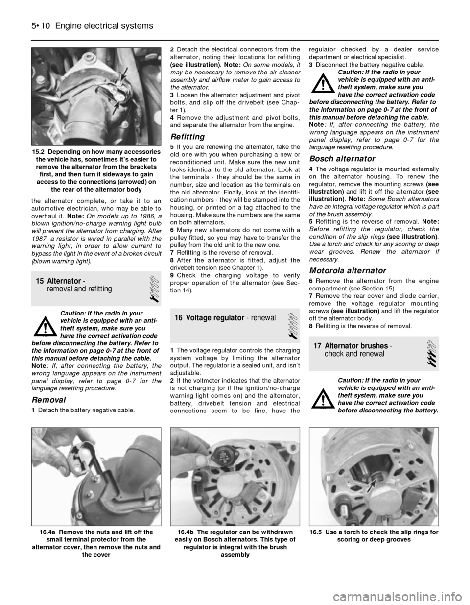
1Detach the battery negative cable.2Detach the electrical connectors from the
alternator, noting their locations for refitting
(see illustration). Note: On some models, it
may be necessary to remove the air cleaner
assembly and airflow meter to gain access to
the alternator.
3Loosen the alternator adjustment and pivot
bolts, and slip off the drivebelt (see Chap-
ter 1).
4Remove the adjustment and pivot bolts,
and separate the alternator from the engine.
Refitting
5If you are renewing the alternator, take the
old one with you when purchasing a new or
reconditioned unit. Make sure the new unit
looks identical to the old alternator. Look at
the terminals - they should be the same in
number, size and location as the terminals on
the old alternator. Finally, look at the identifi-
cation numbers - they will be stamped into the
housing, or printed on a tag attached to the
housing. Make sure the numbers are the same
on both alternators.
6Many new alternators do not come with a
pulley fitted, so you may have to transfer the
pulley from the old unit to the new one.
7Refitting is the reverse of removal.
8After the alternator is fitted, adjust the
drivebelt tension (see Chapter 1).
9Check the charging voltage to verify
proper operation of the alternator (see Sec-
tion 14).
16 Voltage regulator- renewal
1
1The voltage regulator controls the charging
system voltage by limiting the alternator
output. The regulator is a sealed unit, and isn’t
adjustable.
2If the voltmeter indicates that the alternator
is not charging (or if the ignition/no-charge
warning light comes on) and the alternator,
battery, drivebelt tension and electrical
connections seem to be fine, have theregulator checked by a dealer service
department or electrical specialist.
3Disconnect the battery negative cable.
Caution: If the radio in your
vehicle is equipped with an anti-
theft system, make sure you
have the correct activation code
before disconnecting the battery. Refer to
the information on page 0-7 at the front of
this manual before detaching the cable.
Note: If, after connecting the battery, the
wrong language appears on the instrument
panel display, refer to page 0-7 for the
language resetting procedure.
Bosch alternator
4The voltage regulator is mounted externally
on the alternator housing. To renew the
regulator, remove the mounting screws (see
illustration)and lift it off the alternator (see
illustration). Note: Some Bosch alternators
have an integral voltage regulator which is part
of the brush assembly.
5Refitting is the reverse of removal. Note:
Before refitting the regulator, check the
condition of the slip rings(see illustration).
Use a torch and check for any scoring or deep
wear grooves. Renew the alternator if
necessary.
Motorola alternator
6Remove the alternator from the engine
compartment (see Section 15).
7Remove the rear cover and diode carrier,
remove the voltage regulator mounting
screws (see illustration)and lift the regulator
off the alternator body.
8Refitting is the reverse of removal.
17 Alternator brushes-
check and renewal
3
Caution: If the radio in your
vehicle is equipped with an anti-
theft system, make sure you
have the correct activation code
before disconnecting the battery.
5•10 Engine electrical systems
16.5 Use a torch to check the slip rings for
scoring or deep grooves16.4b The regulator can be withdrawn
easily on Bosch alternators. This type of
regulator is integral with the brush
assembly16.4a Remove the nuts and lift off the
small terminal protector from the
alternator cover, then remove the nuts and
the cover
15.2 Depending on how many accessories
the vehicle has, sometimes it’s easier to
remove the alternator from the brackets
first, and then turn it sideways to gain
access to the connections (arrowed) on
the rear of the alternator body
Page 121 of 228
Refer to the information on page 0-7 at the
front of this manual before detaching the
cable.
Note: If, after connecting the battery, the
wrong language appears on the instrument
panel display, refer to page 0-7 for the
language resetting procedure.
1Disconnect the battery negative cable.
Bosch alternator
2Remove the voltage regulator from the back
of the alternator (see Section 16).
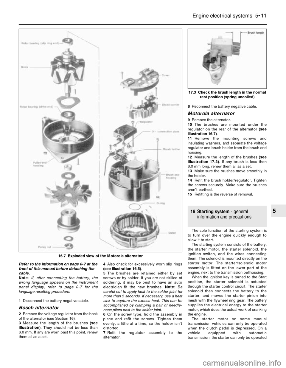
3Measure the length of the brushes (see
illustration). They should not be less than
6.0 mm. If any are worn past this point, renew
them all as a set. 4Also check for excessively worn slip rings
(see illustration 16.5).
5The brushes are retained either by set
screws or by solder. If you are not skilled at
soldering, it may be best to have an auto
electrician fit the new brushes. Note: Be
careful not to apply heat to the solder joint for
more than 5 seconds. If necessary, use a heat
sink to capture the excess heat. This can be
accomplished by clamping a pair of needle-
nose pliers next to the solder joint.
6On the screw type, hold the assembly in
place and refit the screws. Tighten them
evenly, a little at a time, so the holder isn’t
distorted.
7Refit the regulator assembly to the
alternator.8Reconnect the battery negative cable.
Motorola alternator
9Remove the alternator.
10The brushes are mounted under the
regulator on the rear of the alternator (see
illustration 16.7).
11Remove the mounting screws and
insulating washers, and separate the voltage
regulator and brush holder from the brush end
housing.
12Measure the length of the brushes (see
illustration 17.3). If any brush is less then
6.0 mm long, renew them all as a set.
13Make sure the brushes move smoothly in
the holder.
14Refit the brush holder/regulator. Tighten
the screws securely. Make sure the brushes
aren’t earthed.
15Refitting is the reverse of removal.
18 Starting system- general
information and precautions
The sole function of the starting system is
to turn over the engine quickly enough to
allow it to start.
The starting system consists of the battery,
the starter motor, the starter solenoid, the
ignition switch, and the wires connecting
them. The solenoid is mounted directly on the
starter motor. The starter/solenoid motor
assembly is fitted on the lower part of the
engine, next to the transmission bellhousing.
When the ignition key is turned to the Start
position, the starter solenoid is actuated
through the starter control circuit. The starter
solenoid then connects the battery to the
starter, and moves the starter pinion into
mesh with the flywheel ring gear. The battery
supplies the electrical energy to the starter
motor, which does the actual work of cranking
the engine.
The starter motor on some manual
transmission vehicles can only be operated
when the clutch pedal is depressed. On a
vehicle equipped with automatic
transmission, the starter can only be operated
Engine electrical systems 5•11
17.3 Check the brush length in the normal
rest position (spring uncoiled)
5
16.7 Exploded view of the Motorola alternator
Page 123 of 228
6
Chapter 6
Engine management and emission control systems
Catalytic converter . . . . . . . . . . . . . . . . . . . . . . . . . . . . . . . . . . . . . . 7
Electronic Control Unit (ECU) - removal and refitting . . . . . . . . . . . . 3
Evaporative emissions control (EVAP) system . . . . . . . . . . . . . . . . . 6
Evaporative emissions control system inspection . . . See Chapter 1
General information . . . . . . . . . . . . . . . . . . . . . . . . . . . . . . . . . . . . . . 1Information sensors . . . . . . . . . . . . . . . . . . . . . . . . . . . . . . . . . . . . . . 4
Motronic engine management system self-diagnosis -
general information . . . . . . . . . . . . . . . . . . . . . . . . . . . . . . . . . . . . 2
Positive crankcase ventilation (PCV) system . . . . . . . . . . . . . . . . . . 5
6•1
Easy,suitable for
novice with little
experienceFairly easy,suitable
for beginner with
some experienceFairly difficult,
suitable for competent
DIY mechanic
Difficult,suitable for
experienced DIY
mechanicVery difficult,
suitable for expert
DIY or professional
Degrees of difficulty Contents
1 General information
To prevent pollution of the atmosphere
from incomplete combustion or evaporation
of the fuel, and to maintain good driveability
and fuel economy, a number of emission
control systems are used on these vehicles.
Not all of these systems are fitted to all
models, but they include the following:
Catalytic converter
Evaporative emission control (EVAP) system
Positive crankcase ventilation (PCV) system
Electronic engine management
The Sections in this Chapter include
general descriptions and checking
procedures within the scope of the home
mechanic, as well as component renewal
procedures (when possible) for each of the
systems listed above.
Before assuming that an emissions control
system is malfunctioning, check the fuel and
ignition systems carefully. The diagnosis of
some emission control devices requires
specialised tools, equipment and training. If
checking and servicing become too difficult,
or if a procedure is beyond your ability,
consult a dealer service department or other
specialist.This doesn’t mean, however, that emission
control systems are particularly difficult to
maintain and repair. You can quickly and
easily perform many checks, and do most of
the regular maintenance at home with
common tune-up and hand tools.
Pay close attention to any special
precautions outlined in this Chapter. It should
be noted that the illustrations of the various
systems may not exactly match the system
fitted on your vehicle because of
changes made by the manufacturer during
production.
2 Motronic engine management
system self-diagnosis-
general information
The Motronic engine management system
control unit (computer) has a built-in self-
diagnosis system, which detects malfunctions
in the system sensors and stores them as
fault codes in its memory. It is not possible
without dedicated test equipment to extract
these fault codes from the control unit.
However, the procedures given in Chapters 4
and 5 may be used to check individual
components and sensors of the Motronic
system. If this fails to pinpoint a fault, then the
vehicle should be taken to a BMW dealer, who
will have the necessary diagnostic
equipment to call up the fault codes from the
control unit. You will then have the
option to repair the fault yourself, or
alternatively have the fault repaired by the
BMW dealer.
3 Electronic control unit (ECU)
- removal and refitting
2
Removal
1The Electronic Control Unit (ECU) is located
either inside the passenger compartment
under the right-hand side of the facia panel on
3-Series models, or in the engine
compartment on the right-hand side on 5-
Series models (see Chapter 4).
2Disconnect the battery negative cable.
Caution: If the radio in your
vehicle is equipped with an anti-
theft system, make sure you
have the correct activation code
before disconnecting the battery. Refer to
the information on page 0-7 at the front of
this manual before detaching the cable.
Note: If, after connecting the battery, the
wrong language appears on the instrument
panel display, refer to page 0-7 for the
language resetting procedure.
3First remove the access cover on models
with the ECU on the right-hand side of the
engine compartment (see Chapter 4).
4If the ECU is located inside the vehicle,
remove the access cover on the right-hand side.
5Unplug the electrical connectors from the
ECU.
6Remove the retaining bolts from the ECU
bracket.
7Carefully remove the ECU. Note: Avoid static
electricity damage to the ECU by wearing rubber
gloves, and do not touch the connector pins.
Refitting
8Refitting is a reversal of removal.
The most frequent cause of
emission system problems is
simply a leaking vacuum hose
or loose wire, so always
check the hose and wiring connections
first.
Page 124 of 228
4 Information sensors
2
Note:Refer to Chapters 4 and 5 for additional
information on the location and diagnosis of
the information sensors that are not covered in
this Section.
Coolant temperature sensor
General description
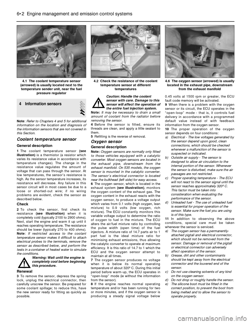
1The coolant temperature sensor (see
illustration)is a thermistor (a resistor which
varies its resistance value in accordance with
temperature changes). The change in the
resistance value regulates the amount of
voltage that can pass through the sensor. At
low temperatures, the sensor’s resistance is
high. As the sensor temperature increases, its
resistance will decrease. Any failure in this
sensor circuit will in most cases be due to a
loose or shorted-out wire; if no wiring
problems are evident, check the sensor as
described below.
Check
2To check the sensor, first check its
resistance (see illustration)when it is
completely cold (typically 2100 to 2900 ohms).
Next, start the engine and warm it up until it
reaches operating temperature. The resistance
should be lower (typically 270 to 400 ohms).
Note: If restricted access to the coolant
temperature sensor makes it difficult to attach
electrical probes to the terminals, remove the
sensor as described below, and perform the
tests in a container of heated water to simulate
the conditions.
Warning: Wait until the engine is
completely cool before beginning
this procedure.
Renewal
3To remove the sensor, depress the spring
lock, unplug the electrical connector, then
carefully unscrew the sensor. Be prepared for
some coolant spillage; to reduce this, have
the new sensor ready for fitting as quickly as
possible.Caution: Handle the coolant
sensor with care. Damage to this
sensor will affect the operation of
the entire fuel injection system.
Note: It may be necessary to drain a small
amount of coolant from the radiator before
removing the sensor.
4Before the sensor is fitted, ensure its
threads are clean, and apply a little sealant to
them.
5Refitting is the reverse of removal.
Oxygen sensor
General description
Note:Oxygen sensors are normally only fitted
to those vehicles equipped with a catalytic
converter. Most oxygen sensors are located in
the exhaust pipe, downstream from the
exhaust manifold. On 535 models, the oxygen
sensor is mounted in the catalytic converter.
The sensor’s electrical connector is located
near the bulkhead (left side) for easy access.
6The oxygen sensor, which is located in the
exhaust system (see illustration), monitors
the oxygen content of the exhaust gas. The
oxygen content in the exhaust reacts with the
oxygen sensor, to produce a voltage output
which varies from 0.1 volts (high oxygen, lean
mixture) to 0.9 volts (low oxygen, rich
mixture). The ECU constantly monitors this
variable voltage output to determine the ratio
of oxygen to fuel in the mixture. The ECU
alters the air/fuel mixture ratio by controlling
the pulse width (open time) of the fuel
injectors. A mixture ratio of 14.7 parts air to 1
part fuel is the ideal mixture ratio for
minimising exhaust emissions, thus allowing
the catalytic converter to operate at maximum
efficiency. It is this ratio of 14.7 to 1 which the
ECU and the oxygen sensor attempt to
maintain at all times.
7The oxygen sensor produces no voltage
when it is below its normal operating
temperature of about 320º C. During this initial
period before warm-up, the ECU operates in
“open-loop” mode (ie without the information
from the sensor).
8If the engine reaches normal operating
temperature and/or has been running for two
or more minutes, and if the oxygen sensor is
producing a steady signal voltage below 0.45 volts at 1500 rpm or greater, the ECU
fault code memory will be activated.
9When there is a problem with the oxygen
sensor or its circuit, the ECU operates in the
“open-loop” mode - that is, it controls fuel
delivery in accordance with a programmed
default value instead of with feedback
information from the oxygen sensor.
10The proper operation of the oxygen
sensor depends on four conditions:
a) Electrical - The low voltages generated by
the sensor depend upon good, clean
connections, which should be checked
whenever a malfunction of the sensor is
suspected or indicated.
b) Outside air supply - The sensor is
designed to allow air circulation to the
internal portion of the sensor. Whenever
the sensor is disturbed, make sure the air
passages are not restricted.
c) Proper operating temperature - The ECU
will not react to the sensor signal until the
sensor reaches approximately 320º C.
This factor must be taken into
consideration when evaluating the
performance of the sensor.
d) Unleaded fuel - The use of unleaded fuel
is essential for proper operation of the
sensor. Make sure the fuel you are using
is of this type.
11In addition to observing the above
conditions, special care must be taken
whenever the sensor is serviced.
a) The oxygen sensor has a permanently-
attached pigtail and electrical connector,
which should not be removed from the
sensor. Damage or removal of the pigtail
or electrical connector can adversely
affect operation of the sensor.
b) Grease, dirt and other contaminants
should be kept away from the electrical
connector and the louvered end of the
sensor.
c) Do not use cleaning solvents of any kind
on the oxygen sensor.
d) Do not drop or roughly handle the sensor.
e) The silicone boot must be fitted in the
correct position, to prevent the boot from
being melted and to allow the sensor to
operate properly.
6•2 Engine management and emission control systems
4.6 The oxygen sensor (arrowed) is usually
located in the exhaust pipe, downstream
from the exhaust manifold4.2 Check the resistance of the coolant
temperature sensor at different
temperatures4.1 The coolant temperature sensor
(arrowed) is usually located next to the
temperature sender unit, near the fuel
pressure regulator
Page 125 of 228
Check
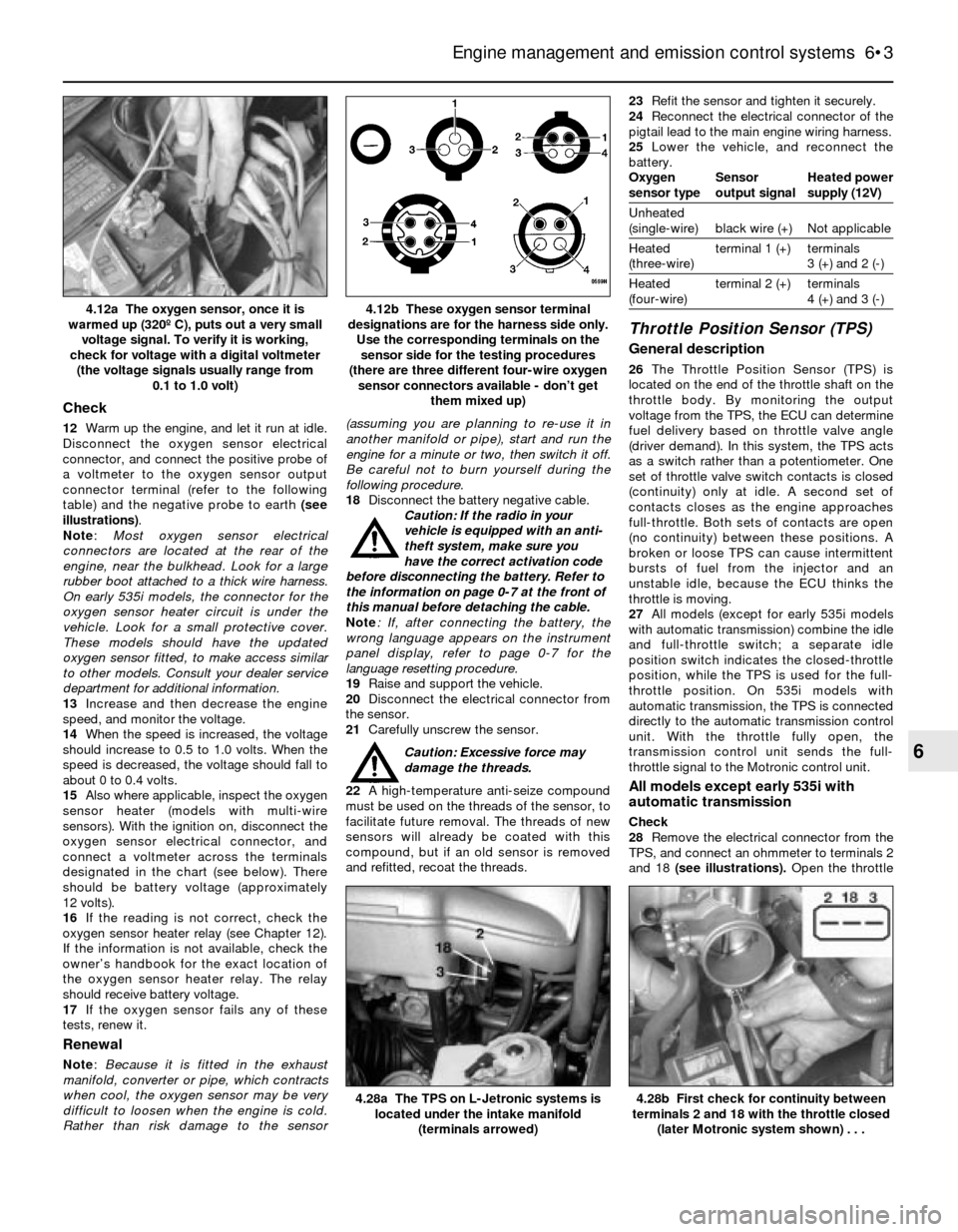
12Warm up the engine, and let it run at idle.
Disconnect the oxygen sensor electrical
connector, and connect the positive probe of
a voltmeter to the oxygen sensor output
connector terminal (refer to the following
table) and the negative probe to earth (see
illustrations).
Note:Most oxygen sensor electrical
connectors are located at the rear of the
engine, near the bulkhead. Look for a large
rubber boot attached to a thick wire harness.
On early 535i models, the connector for the
oxygen sensor heater circuit is under the
vehicle. Look for a small protective cover.
These models should have the updated
oxygen sensor fitted, to make access similar
to other models. Consult your dealer service
department for additional information.
13Increase and then decrease the engine
speed, and monitor the voltage.
14When the speed is increased, the voltage
should increase to 0.5 to 1.0 volts. When the
speed is decreased, the voltage should fall to
about 0 to 0.4 volts.
15Also where applicable, inspect the oxygen
sensor heater (models with multi-wire
sensors). With the ignition on, disconnect the
oxygen sensor electrical connector, and
connect a voltmeter across the terminals
designated in the chart (see below). There
should be battery voltage (approximately
12 volts).
16If the reading is not correct, check the
oxygen sensor heater relay (see Chapter 12).
If the information is not available, check the
owner’s handbook for the exact location of
the oxygen sensor heater relay. The relay
should receive battery voltage.
17If the oxygen sensor fails any of these
tests, renew it.
Renewal
Note: Because it is fitted in the exhaust
manifold, converter or pipe, which contracts
when cool, the oxygen sensor may be very
difficult to loosen when the engine is cold.
Rather than risk damage to the sensor(assuming you are planning to re-use it in
another manifold or pipe), start and run the
engine for a minute or two, then switch it off.
Be careful not to burn yourself during the
following procedure.
18Disconnect the battery negative cable.
Caution: If the radio in your
vehicle is equipped with an anti-
theft system, make sure you
have the correct activation code
before disconnecting the battery. Refer to
the information on page 0-7 at the front of
this manual before detaching the cable.
Note: If, after connecting the battery, the
wrong language appears on the instrument
panel display, refer to page 0-7 for the
language resetting procedure.
19Raise and support the vehicle.
20Disconnect the electrical connector from
the sensor.
21Carefully unscrew the sensor.
Caution: Excessive force may
damage the threads.
22A high-temperature anti-seize compound
must be used on the threads of the sensor, to
facilitate future removal. The threads of new
sensors will already be coated with this
compound, but if an old sensor is removed
and refitted, recoat the threads.23Refit the sensor and tighten it securely.
24Reconnect the electrical connector of the
pigtail lead to the main engine wiring harness.
25Lower the vehicle, and reconnect the
battery.
Oxygen Sensor Heated power
sensor type output signal supply (12V)
Unheated
(single-wire) black wire (+) Not applicable
Heated terminal 1 (+) terminals
(three-wire) 3 (+) and 2 (-)
Heated terminal 2 (+) terminals
(four-wire) 4 (+) and 3 (-)
Throttle Position Sensor (TPS)
General description
26The Throttle Position Sensor (TPS) is
located on the end of the throttle shaft on the
throttle body. By monitoring the output
voltage from the TPS, the ECU can determine
fuel delivery based on throttle valve angle
(driver demand). In this system, the TPS acts
as a switch rather than a potentiometer. One
set of throttle valve switch contacts is closed
(continuity) only at idle. A second set of
contacts closes as the engine approaches
full-throttle. Both sets of contacts are open
(no continuity) between these positions. A
broken or loose TPS can cause intermittent
bursts of fuel from the injector and an
unstable idle, because the ECU thinks the
throttle is moving.
27All models (except for early 535i models
with automatic transmission) combine the idle
and full-throttle switch; a separate idle
position switch indicates the closed-throttle
position, while the TPS is used for the full-
throttle position. On 535i models with
automatic transmission, the TPS is connected
directly to the automatic transmission control
unit. With the throttle fully open, the
transmission control unit sends the full-
throttle signal to the Motronic control unit.
All models except early 535i with
automatic transmission
Check
28Remove the electrical connector from the
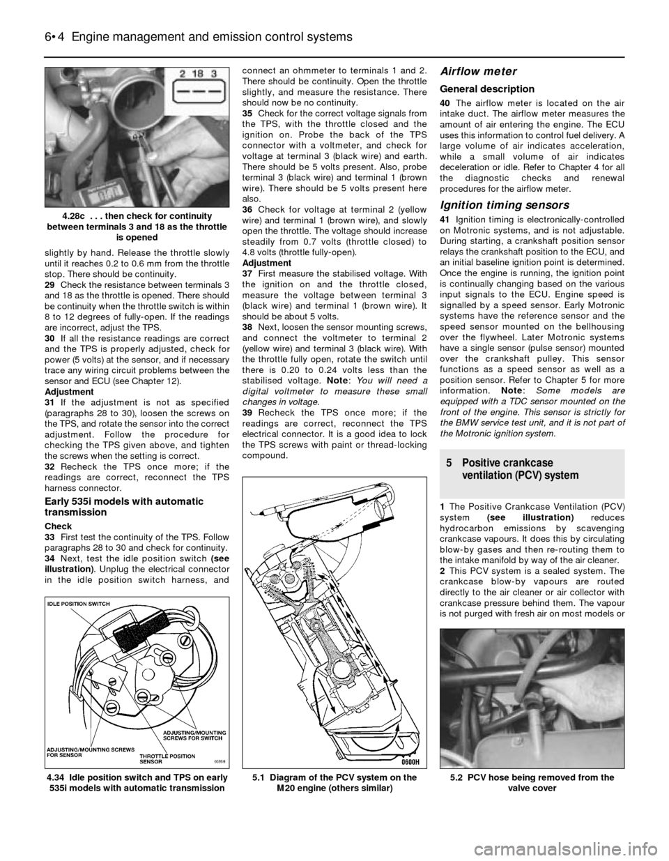
TPS, and connect an ohmmeter to terminals 2
and 18 (see illustrations). Open the throttle
Engine management and emission control systems 6•3
4.12b These oxygen sensor terminal
designations are for the harness side only.
Use the corresponding terminals on the
sensor side for the testing procedures
(there are three different four-wire oxygen
sensor connectors available - don’t get
them mixed up)4.12a The oxygen sensor, once it is
warmed up (320º C), puts out a very small
voltage signal. To verify it is working,
check for voltage with a digital voltmeter
(the voltage signals usually range from
0.1 to 1.0 volt)
4.28b First check for continuity between
terminals 2 and 18 with the throttle closed
(later Motronic system shown) . . .4.28a The TPS on L-Jetronic systems is
located under the intake manifold
(terminals arrowed)
6
Page 126 of 228
slightly by hand. Release the throttle slowly
until it reaches 0.2 to 0.6 mm from the throttle
stop. There should be continuity.
29Check the resistance between terminals 3
and 18 as the throttle is opened. There should
be continuity when the throttle switch is within
8 to 12 degrees of fully-open. If the readings
are incorrect, adjust the TPS.
30If all the resistance readings are correct
and the TPS is properly adjusted, check for
power (5 volts) at the sensor, and if necessary
trace any wiring circuit problems between the
sensor and ECU (see Chapter 12).
Adjustment
31If the adjustment is not as specified
(paragraphs 28 to 30), loosen the screws on
the TPS, and rotate the sensor into the correct
adjustment. Follow the procedure for
checking the TPS given above, and tighten
the screws when the setting is correct.
32Recheck the TPS once more; if the
readings are correct, reconnect the TPS
harness connector.
Early 535i models with automatic
transmission
Check
33First test the continuity of the TPS. Follow
paragraphs 28 to 30 and check for continuity.
34Next, test the idle position switch (see
illustration). Unplug the electrical connector
in the idle position switch harness, andconnect an ohmmeter to terminals 1 and 2.
There should be continuity. Open the throttle
slightly, and measure the resistance. There
should now be no continuity.
35Check for the correct voltage signals from
the TPS, with the throttle closed and the
ignition on. Probe the back of the TPS
connector with a voltmeter, and check for
voltage at terminal 3 (black wire) and earth.
There should be 5 volts present. Also, probe
terminal 3 (black wire) and terminal 1 (brown
wire). There should be 5 volts present here
also.
36Check for voltage at terminal 2 (yellow
wire) and terminal 1 (brown wire), and slowly
open the throttle. The voltage should increase
steadily from 0.7 volts (throttle closed) to
4.8 volts (throttle fully-open).
Adjustment
37First measure the stabilised voltage. With
the ignition on and the throttle closed,
measure the voltage between terminal 3
(black wire) and terminal 1 (brown wire). It
should be about 5 volts.
38Next, loosen the sensor mounting screws,
and connect the voltmeter to terminal 2
(yellow wire) and terminal 3 (black wire). With
the throttle fully open, rotate the switch until
there is 0.20 to 0.24 volts less than the
stabilised voltage. Note: You will need a
digital voltmeter to measure these small
changes in voltage.
39Recheck the TPS once more; if the
readings are correct, reconnect the TPS
electrical connector. It is a good idea to lock
the TPS screws with paint or thread-locking
compound.
Airflow meter
General description
40The airflow meter is located on the air
intake duct. The airflow meter measures the
amount of air entering the engine. The ECU
uses this information to control fuel delivery. A
large volume of air indicates acceleration,
while a small volume of air indicates
deceleration or idle. Refer to Chapter 4 for all
the diagnostic checks and renewal
procedures for the airflow meter.
Ignition timing sensors
41Ignition timing is electronically-controlled
on Motronic systems, and is not adjustable.
During starting, a crankshaft position sensor
relays the crankshaft position to the ECU, and
an initial baseline ignition point is determined.
Once the engine is running, the ignition point
is continually changing based on the various
input signals to the ECU. Engine speed is
signalled by a speed sensor. Early Motronic
systems have the reference sensor and the
speed sensor mounted on the bellhousing
over the flywheel. Later Motronic systems
have a single sensor (pulse sensor) mounted
over the crankshaft pulley. This sensor
functions as a speed sensor as well as a
position sensor. Refer to Chapter 5 for more
information. Note: Some models are
equipped with a TDC sensor mounted on the
front of the engine. This sensor is strictly for
the BMW service test unit, and it is not part of
the Motronic ignition system.
5 Positive crankcase
ventilation (PCV) system
1The Positive Crankcase Ventilation (PCV)
system (see illustration)reduces
hydrocarbon emissions by scavenging
crankcase vapours. It does this by circulating
blow-by gases and then re-routing them to
the intake manifold by way of the air cleaner.
2This PCV system is a sealed system. The
crankcase blow-by vapours are routed
directly to the air cleaner or air collector with
crankcase pressure behind them. The vapour
is not purged with fresh air on most models or
6•4 Engine management and emission control systems
5.2 PCV hose being removed from the
valve cover5.1 Diagram of the PCV system on the
M20 engine (others similar)4.34 Idle position switch and TPS on early
535i models with automatic transmission
4.28c . . . then check for continuity
between terminals 3 and 18 as the throttle
is opened
Page 127 of 228
filtered with a flame trap like most
conventional systems. There are no
conventional PCV valves fitted on these
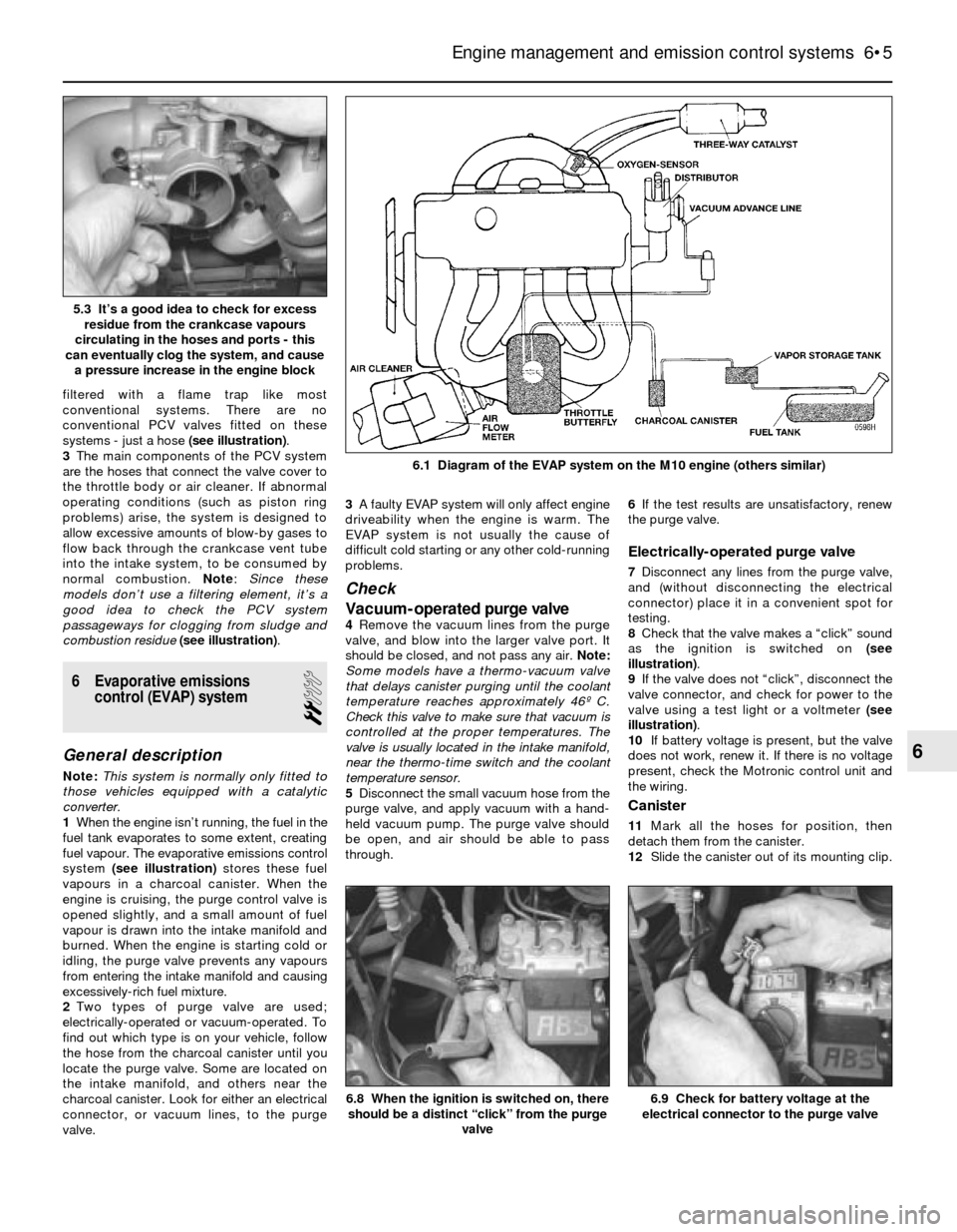
systems - just a hose (see illustration).
3The main components of the PCV system
are the hoses that connect the valve cover to
the throttle body or air cleaner. If abnormal
operating conditions (such as piston ring
problems) arise, the system is designed to
allow excessive amounts of blow-by gases to
flow back through the crankcase vent tube
into the intake system, to be consumed by
normal combustion. Note: Since these
models don’t use a filtering element, it’s a
good idea to check the PCV system
passageways for clogging from sludge and
combustion residue(see illustration).
6 Evaporative emissions
control (EVAP) system
2
General description
Note:This system is normally only fitted to
those vehicles equipped with a catalytic
converter.
1When the engine isn’t running, the fuel in the
fuel tank evaporates to some extent, creating
fuel vapour. The evaporative emissions control
system (see illustration)stores these fuel
vapours in a charcoal canister. When the
engine is cruising, the purge control valve is
opened slightly, and a small amount of fuel
vapour is drawn into the intake manifold and
burned. When the engine is starting cold or
idling, the purge valve prevents any vapours
from entering the intake manifold and causing
excessively-rich fuel mixture.
2Two types of purge valve are used;
electrically-operated or vacuum-operated. To
find out which type is on your vehicle, follow
the hose from the charcoal canister until you
locate the purge valve. Some are located on
the intake manifold, and others near the
charcoal canister. Look for either an electrical
connector, or vacuum lines, to the purge
valve.3A faulty EVAP system will only affect engine
driveability when the engine is warm. The
EVAP system is not usually the cause of
difficult cold starting or any other cold-running
problems.
Check
Vacuum-operated purge valve
4Remove the vacuum lines from the purge
valve, and blow into the larger valve port. It
should be closed, and not pass any air. Note:
Some models have a thermo-vacuum valve
that delays canister purging until the coolant
temperature reaches approximately 46º C.
Check this valve to make sure that vacuum is
controlled at the proper temperatures. The
valve is usually located in the intake manifold,
near the thermo-time switch and the coolant
temperature sensor.
5Disconnect the small vacuum hose from the
purge valve, and apply vacuum with a hand-
held vacuum pump. The purge valve should
be open, and air should be able to pass
through.6If the test results are unsatisfactory, renew
the purge valve.
Electrically-operated purge valve
7Disconnect any lines from the purge valve,
and (without disconnecting the electrical
connector) place it in a convenient spot for
testing.
8Check that the valve makes a “click” sound
as the ignition is switched on (see
illustration).
9If the valve does not “click”, disconnect the
valve connector, and check for power to the
valve using a test light or a voltmeter (see
illustration).
10If battery voltage is present, but the valve
does not work, renew it. If there is no voltage
present, check the Motronic control unit and
the wiring.
Canister
11Mark all the hoses for position, then
detach them from the canister.
12Slide the canister out of its mounting clip.
Engine management and emission control systems 6•5
6.1 Diagram of the EVAP system on the M10 engine (others similar)
6.9 Check for battery voltage at the
electrical connector to the purge valve6.8 When the ignition is switched on, there
should be a distinct “click” from the purge
valve
6
5.3 It’s a good idea to check for excess
residue from the crankcase vapours
circulating in the hoses and ports - this
can eventually clog the system, and cause
a pressure increase in the engine block
Page 128 of 228
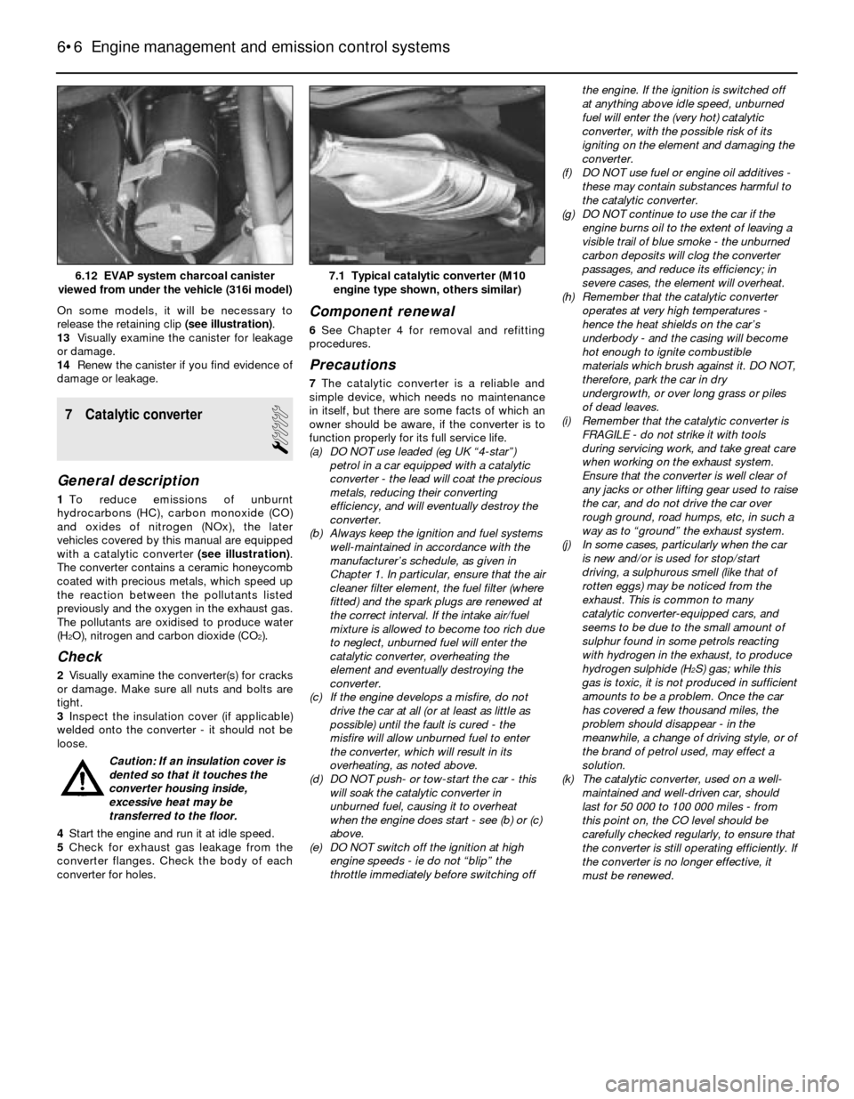
On some models, it will be necessary to
release the retaining clip (see illustration).
13Visually examine the canister for leakage
or damage.
14Renew the canister if you find evidence of
damage or leakage.
7 Catalytic converter
1
General description
1To reduce emissions of unburnt
hydrocarbons (HC), carbon monoxide (CO)
and oxides of nitrogen (NOx), the later
vehicles covered by this manual are equipped
with a catalytic converter (see illustration).
The converter contains a ceramic honeycomb
coated with precious metals, which speed up
the reaction between the pollutants listed
previously and the oxygen in the exhaust gas.
The pollutants are oxidised to produce water
(H
2O), nitrogen and carbon dioxide (CO2).
Check
2Visually examine the converter(s) for cracks
or damage. Make sure all nuts and bolts are
tight.
3Inspect the insulation cover (if applicable)
welded onto the converter - it should not be
loose.
Caution: If an insulation cover is
dented so that it touches the
converter housing inside,
excessive heat may be
transferred to the floor.
4Start the engine and run it at idle speed.
5Check for exhaust gas leakage from the
converter flanges. Check the body of each
converter for holes.
Component renewal
6See Chapter 4 for removal and refitting
procedures.
Precautions
7The catalytic converter is a reliable and
simple device, which needs no maintenance
in itself, but there are some facts of which an
owner should be aware, if the converter is to
function properly for its full service life.
(a) DO NOT use leaded (eg UK “4-star”)
petrol in a car equipped with a catalytic
converter - the lead will coat the precious
metals, reducing their converting
efficiency, and will eventually destroy the
converter.
(b) Always keep the ignition and fuel systems
well-maintained in accordance with the
manufacturer’s schedule, as given in
Chapter 1. In particular, ensure that the air
cleaner filter element, the fuel filter (where
fitted) and the spark plugs are renewed at
the correct interval. If the intake air/fuel
mixture is allowed to become too rich due
to neglect, unburned fuel will enter the
catalytic converter, overheating the
element and eventually destroying the
converter.
(c) If the engine develops a misfire, do not
drive the car at all (or at least as little as
possible) until the fault is cured - the
misfire will allow unburned fuel to enter
the converter, which will result in its
overheating, as noted above.
(d) DO NOT push- or tow-start the car - this
will soak the catalytic converter in
unburned fuel, causing it to overheat
when the engine does start - see (b) or (c)
above.
(e) DO NOT switch off the ignition at high
engine speeds - ie do not “blip” the
throttle immediately before switching offthe engine. If the ignition is switched off
at anything above idle speed, unburned
fuel will enter the (very hot) catalytic
converter, with the possible risk of its
igniting on the element and damaging the
converter.
(f) DO NOT use fuel or engine oil additives -
these may contain substances harmful to
the catalytic converter.
(g) DO NOT continue to use the car if the
engine burns oil to the extent of leaving a
visible trail of blue smoke - the unburned
carbon deposits will clog the converter
passages, and reduce its efficiency; in
severe cases, the element will overheat.
(h) Remember that the catalytic converter
operates at very high temperatures -
hence the heat shields on the car’s
underbody - and the casing will become
hot enough to ignite combustible
materials which brush against it. DO NOT,
therefore, park the car in dry
undergrowth, or over long grass or piles
of dead leaves.
(i) Remember that the catalytic converter is
FRAGILE - do not strike it with tools
during servicing work, and take great care
when working on the exhaust system.
Ensure that the converter is well clear of
any jacks or other lifting gear used to raise
the car, and do not drive the car over
rough ground, road humps, etc, in such a
way as to “ground” the exhaust system.
(j) In some cases, particularly when the car
is new and/or is used for stop/start
driving, a sulphurous smell (like that of
rotten eggs) may be noticed from the
exhaust. This is common to many
catalytic converter-equipped cars, and
seems to be due to the small amount of
sulphur found in some petrols reacting
with hydrogen in the exhaust, to produce
hydrogen sulphide (H
2S) gas; while this
gas is toxic, it is not produced in sufficient
amounts to be a problem. Once the car
has covered a few thousand miles, the
problem should disappear - in the
meanwhile, a change of driving style, or of
the brand of petrol used, may effect a
solution.
(k) The catalytic converter, used on a well-
maintained and well-driven car, should
last for 50 000 to 100 000 miles - from
this point on, the CO level should be
carefully checked regularly, to ensure that
the converter is still operating efficiently. If
the converter is no longer effective, it
must be renewed.
6•6 Engine management and emission control systems
7.1 Typical catalytic converter (M10
engine type shown, others similar)6.12 EVAP system charcoal canister
viewed from under the vehicle (316i model)
Page 130 of 228

Torque wrench settingsNm
Front disc brake caliper
Caliper guide (mounting) bolts . . . . . . . . . . . . . . . . . . . . . . . . . . . . . . 30 to 35
Caliper bracket-to-strut housing bolts
3-Series, E30 . . . . . . . . . . . . . . . . . . . . . . . . . . . . . . . . . . . . . . . . . . 123
5-Series, E28 (“old-shape”) . . . . . . . . . . . . . . . . . . . . . . . . . . . . . . . 123
5-Series, E34 (“new-shape”) . . . . . . . . . . . . . . . . . . . . . . . . . . . . . . 110
Rear disc brake caliper
Caliper guide (mounting) bolts . . . . . . . . . . . . . . . . . . . . . . . . . . . . . . 30 to 35
Carrier-to-trailing arm bolts . . . . . . . . . . . . . . . . . . . . . . . . . . . . . . . . 67
Brake hose-to-caliper fitting . . . . . . . . . . . . . . . . . . . . . . . . . . . . . . . . . . 14 to 17
Master cylinder-to-brake servo nuts
3-Series . . . . . . . . . . . . . . . . . . . . . . . . . . . . . . . . . . . . . . . . . . . . . . . . 24
5-Series . . . . . . . . . . . . . . . . . . . . . . . . . . . . . . . . . . . . . . . . . . . . . . . . 25 to 29
Brake servo mounting nuts . . . . . . . . . . . . . . . . . . . . . . . . . . . . . . . . . . . 22 to 24
Hydraulic line-to-hydraulic brake servo threaded
fittings - 5-Series, E28 (“old-shape”) . . . . . . . . . . . . . . . . . . . . . . . . . . . 31
Wheel bolts . . . . . . . . . . . . . . . . . . . . . . . . . . . . . . . . . . . . . . . . . . . . . . . See Chapter 1
9•2 Braking system
1 General information
All 3-Series models, and 5-Series E28 (“old-
shape”) models, are equipped with front disc
brakes and either rear drum or rear disc
brakes. 5-Series E34 (“new-shape”) models
have disc brakes front and rear. Front and
rear brakes are self-adjusting on all models.
Some later models are equipped with an Anti-
lock Braking System (ABS); this is described
in Section 2.
Hydraulic system
The hydraulic system consists of two
separate circuits. The master cylinder has
separate reservoirs for the two circuits; in the
event of a leak or failure in one hydraulic
circuit, the other circuit will remain operative.
Brake servo
The vacuum brake servo, utilising engine
manifold vacuum and atmospheric pressure
to provide assistance to the hydraulically
operated brakes, is mounted on the bulkhead
in the engine compartment.
A hydraulic brake servo system is used on
5-Series E28 models. This system uses
hydraulic pressure from the power steering
pump to assist braking.
Handbrake
The handbrake operates the rear brakes,
and is cable-operated via a lever mounted in
the centre console. The handbrake assembly
on rear drum brake models is part of the rear
drum brake assembly, and is self-adjusting.
On rear disc brake models, the handbrake
uses a pair of brake shoes located inside the
centre portion of the rear brake disc, and is
manually-adjusted.
Brake pad wear warning system
The brake pad wear warning system is
linked to a red warning light in the instrumentcluster, which comes on when the brake pads
have worn down to the point at which they
require renewal. DO NOT ignore this reminder.
If you don’t renew the pads shortly after the
brake pad wear warning light comes on, the
brake discs will be damaged.
On some models, the brake pad wear
warning system also includes an early
warning light that comes on only when the
brake pedal is depressed, letting you know in
advance that the pads need to be renewed.
The wear sensor is attached to the brake
pads. The sensor is located at the left front
wheel; on some models, there is another
sensor at the right rear wheel. The wear
sensor is part of a closed circuit. Once the
pads wear down to the point at which they’re
flush with the sensor, the disc grinds away the
side of the sensor facing the disc. Thus, the
wire inside the sensor is broken, and the red
light on the instrument panel comes on.
Always check the sensor(s) when renewing
the pads. If you change the pads before the
warning light comes on, the sensor(s) may still
be good; once the light has come on, renew
the sensor.
Service
After completing any operation involving
dismantling of any part of the brake system,
always test drive the vehicle to check for
proper braking performance before resuming
normal driving. When testing the brakes, try to
select a clean, dry, road with no camber (ie as
flat as possible) and with no other traffic.
Conditions other than these can lead to
inaccurate test results.
Test the brakes at various speeds with both
light and heavy pedal pressure. The vehicle
should stop evenly, without pulling to one side
or the other. Avoid locking the brakes,
because this slides the tyres and diminishes
braking efficiency and control of the vehicle.
Tyres, vehicle load and wheel alignment are
factors which also affect braking
performance.
2 Anti-lock Braking system
(ABS)- general information
The Anti-lock Braking System is designed
to maintain vehicle control, directional stability
and optimum deceleration under severe
braking conditions on most road surfaces. It
does so by monitoring the rotational speed of
each wheel and controlling the brake line
pressure to each wheel during braking. This
prevents the wheels from locking up.
The ABS system has three main
components - the wheel speed sensors, the
electronic control unit, and the hydraulic
control unit. The sensors - one at each wheel
since 1985, but at both front wheels and one
at the rear differential on earlier models - send
a variable voltage signal to the control unit,
which monitors these signals, compares them
to its program information, and determines
whether a wheel is about to lock up. When a
wheel is about to lock up, the control unit
signals the hydraulic unit to reduce hydraulic
pressure (or not increase it further) at that
wheel’s brake caliper. Pressure modulation is
handled by electrically-operated solenoid
valves.
If a problem develops within the system, an
“ABS” warning light will glow on the
dashboard. Sometimes, a visual inspection of
the ABS system can help you locate the
problem. Carefully inspect the ABS wiring
harness. Pay particularly close attention to the
harness and connections near each wheel.
Look for signs of chafing and other damage
caused by incorrectly-routed wires. If a wheel
sensor harness is damaged, the sensor
should be renewed (the harness and sensor
are integral).
Warning: DO NOT try to repair an
ABS wiring harness. The ABS
system is sensitive to even the
smallest changes in resistance. Repairing
the harness could alter resistance values