service interval reset BMW 3 SERIES 1987 E30 Workshop Manual
[x] Cancel search | Manufacturer: BMW, Model Year: 1987, Model line: 3 SERIES, Model: BMW 3 SERIES 1987 E30Pages: 228, PDF Size: 7.04 MB
Page 14 of 228

Maintenance schedule
The following maintenance intervals are based on the assumption
that the vehicle owner will be doing the maintenance or service work,
as opposed to having a dealer service department do the work.
Although the time/mileage intervals are loosely based on factory rec-
ommendations, most have been shortened to ensure, for example, that
such items as lubricants and fluids are checked/changed at intervals
that promote maximum engine/driveline service life. Also, subject to
the preference of the individual owner interested in keeping his or her
vehicle in peak condition at all times, and with the vehicle’s ultimate
resale in mind, many of the maintenance procedures may be
performed more often than recommended in the following schedule.
We encourage such owner initiative.
When the vehicle is new, it should be serviced initially by a factory-
authorised dealer service department, to protect the factory warranty.
In many cases, the initial maintenance check is done at no cost to the
owner (check with your dealer service department for more
information).
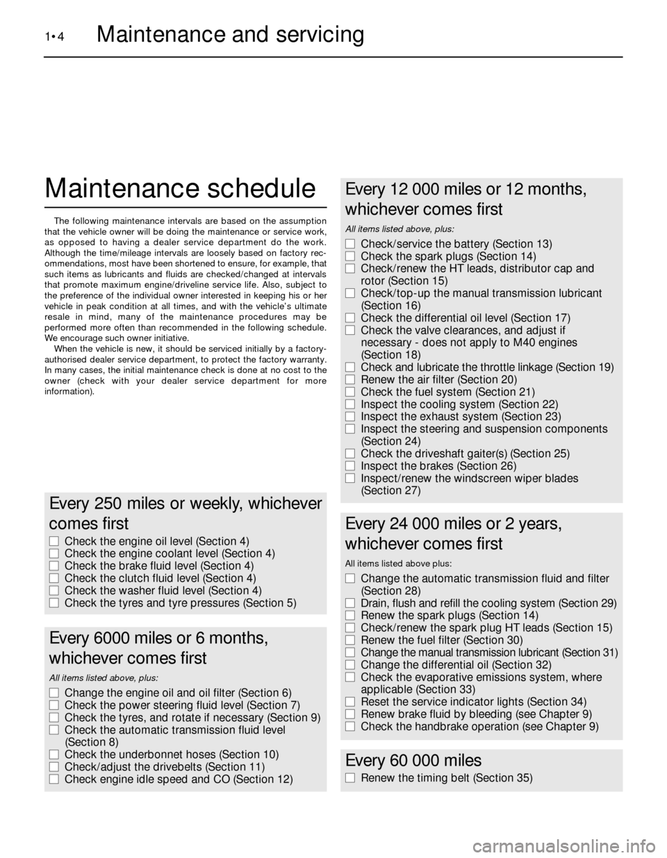
1•4Maintenance and servicing
Every 250 miles or weekly, whichever
comes first
m mCheck the engine oil level (Section 4)
m mCheck the engine coolant level (Section 4)
m mCheck the brake fluid level (Section 4)
m mCheck the clutch fluid level (Section 4)
m mCheck the washer fluid level (Section 4)
m mCheck the tyres and tyre pressures (Section 5)
Every 6000 miles or 6 months,
whichever comes first
All items listed above, plus:
m mChange the engine oil and oil filter (Section 6)
m mCheck the power steering fluid level (Section 7)
m mCheck the tyres, and rotate if necessary (Section 9)
m mCheck the automatic transmission fluid level
(Section 8)
m mCheck the underbonnet hoses (Section 10)
m mCheck/adjust the drivebelts (Section 11)
m mCheck engine idle speed and CO (Section 12)
Every 12 000 miles or 12 months,
whichever comes first
All items listed above, plus:
m mCheck/service the battery (Section 13)
m mCheck the spark plugs (Section 14)
m mCheck/renew the HT leads, distributor cap and
rotor (Section 15)
m mCheck/top-up the manual transmission lubricant
(Section 16)
m mCheck the differential oil level (Section 17)
m mCheck the valve clearances, and adjust if
necessary - does not apply to M40 engines
(Section 18)
m mCheck and lubricate the throttle linkage (Section 19)
m mRenew the air filter (Section 20)
m mCheck the fuel system (Section 21)
m mInspect the cooling system (Section 22)
m mInspect the exhaust system (Section 23)
m mInspect the steering and suspension components
(Section 24)
m mCheck the driveshaft gaiter(s) (Section 25)
m mInspect the brakes (Section 26)
m mInspect/renew the windscreen wiper blades
(Section 27)
Every 24 000 miles or 2 years,
whichever comes first
All items listed above plus:
m mChange the automatic transmission fluid and filter
(Section 28)
m mDrain, flush and refill the cooling system (Section 29)
m mRenew the spark plugs (Section 14)
m mCheck/renew the spark plug HT leads (Section 15)
m mRenew the fuel filter (Section 30)
m mChange the manual transmission lubricant (Section 31)
m mChange the differential oil (Section 32)
m mCheck the evaporative emissions system, where
applicable (Section 33)
m mReset the service indicator lights (Section 34)
m mRenew brake fluid by bleeding (see Chapter 9)
m mCheck the handbrake operation (see Chapter 9)
Every 60 000 miles
m
mRenew the timing belt (Section 35)
Page 36 of 228

the lubricant will be hot, it would be wise to
wear rubber gloves.
3Raise the vehicle and place it on axle
stands. Make sure it is safely supported, and
as level as possible.
4Move the necessary equipment under the
vehicle, being careful not to touch any of the
hot exhaust components.
5Place the drain pan under the transmission,
and remove the filler/level plug from the side
of the transmission. Loosen the drain plug
(see illustration).
6Carefully remove the drain plug. Be careful
not to burn yourself on the lubricant.
7Allow the lubricant to drain completely.
Clean the drain plug thoroughly, then refit and
tighten it securely.
8Refer to Section 16 and fill the transmission
with new lubricant, then refit the filler/level
plug, tightening it securely.
9Lower the vehicle. Check for leaks at the
drain plug after the first few miles of driving.
32 Differential lubricant change
1
1Drive the vehicle for several miles to warm
up the differential lubricant, then raise the
vehicle and support it securely on axle stands.
2Move a drain pan, rags, newspapers and an
Allen key under the vehicle. Since the
lubricant will be hot, wear rubber gloves to
prevent burns.
3Remove the filler/level plug from the
differential; this is the upper of the two plugs.
4With the drain pan under the differential,
loosen the drain plug; this is the lower of the
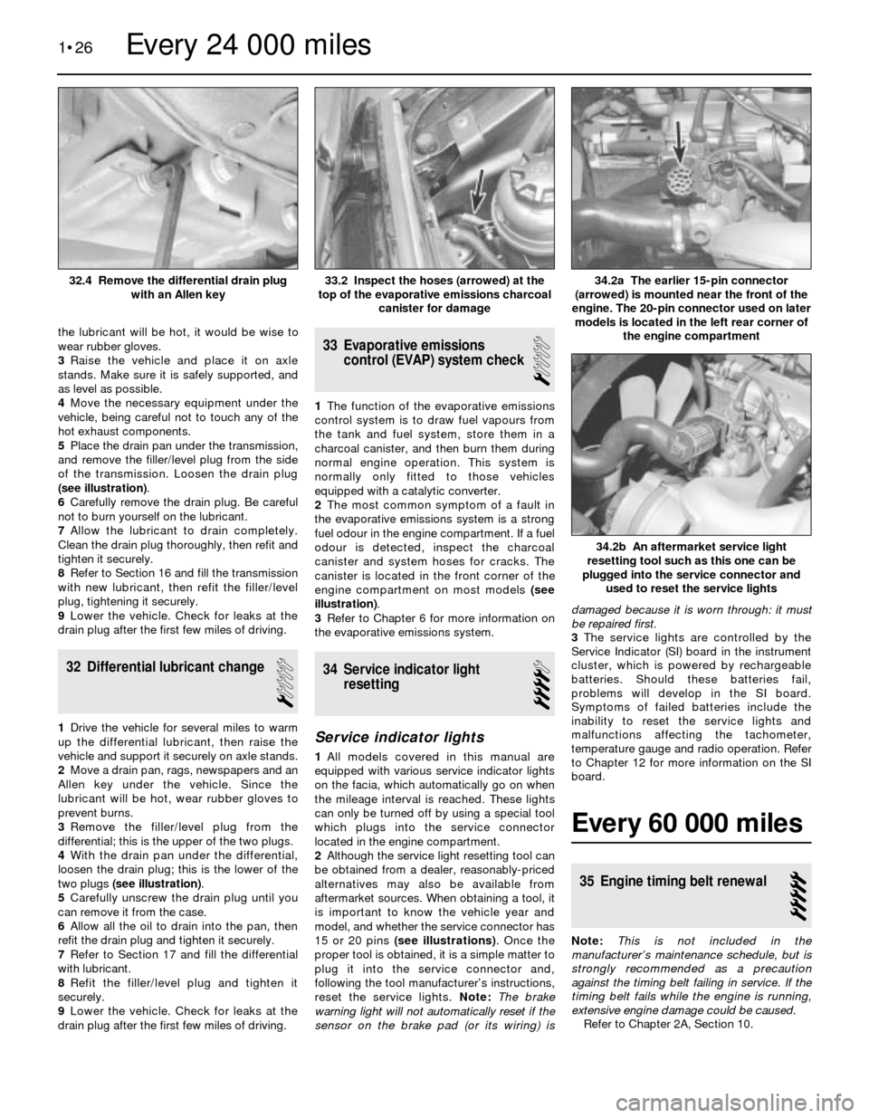
two plugs (see illustration).
5Carefully unscrew the drain plug until you
can remove it from the case.
6Allow all the oil to drain into the pan, then
refit the drain plug and tighten it securely.
7Refer to Section 17 and fill the differential
with lubricant.
8Refit the filler/level plug and tighten it
securely.
9Lower the vehicle. Check for leaks at the
drain plug after the first few miles of driving.
33 Evaporative emissions
control (EVAP) system check
1
1The function of the evaporative emissions
control system is to draw fuel vapours from
the tank and fuel system, store them in a
charcoal canister, and then burn them during
normal engine operation. This system is
normally only fitted to those vehicles
equipped with a catalytic converter.
2The most common symptom of a fault in
the evaporative emissions system is a strong
fuel odour in the engine compartment. If a fuel
odour is detected, inspect the charcoal
canister and system hoses for cracks. The
canister is located in the front corner of the
engine compartment on most models (see
illustration).
3Refer to Chapter 6 for more information on
the evaporative emissions system.
34 Service indicator light
resetting
4
Service indicator lights
1All models covered in this manual are
equipped with various service indicator lights
on the facia, which automatically go on when
the mileage interval is reached. These lights
can only be turned off by using a special tool
which plugs into the service connector
located in the engine compartment.
2Although the service light resetting tool can
be obtained from a dealer, reasonably-priced
alternatives may also be available from
aftermarket sources. When obtaining a tool, it
is important to know the vehicle year and
model, and whether the service connector has
15 or 20 pins (see illustrations). Once the
proper tool is obtained, it is a simple matter to
plug it into the service connector and,
following the tool manufacturer’s instructions,
reset the service lights. Note: The brake
warning light will not automatically reset if the
sensor on the brake pad (or its wiring) isdamaged because it is worn through: it must
be repaired first.
3The service lights are controlled by the
Service Indicator (SI) board in the instrument
cluster, which is powered by rechargeable
batteries. Should these batteries fail,
problems will develop in the SI board.
Symptoms of failed batteries include the
inability to reset the service lights and
malfunctions affecting the tachometer,
temperature gauge and radio operation. Refer
to Chapter 12 for more information on the SI
board.
Every 60 000 miles
35 Engine timing belt renewal
5
Note:This is not included in the
manufacturer’s maintenance schedule, but is
strongly recommended as a precaution
against the timing belt failing in service. If the
timing belt fails while the engine is running,
extensive engine damage could be caused.
Refer to Chapter 2A, Section 10.
1•26
34.2b An aftermarket service light
resetting tool such as this one can be
plugged into the service connector and
used to reset the service lights
34.2a The earlier 15-pin connector
(arrowed) is mounted near the front of the
engine. The 20-pin connector used on later
models is located in the left rear corner of
the engine compartment33.2 Inspect the hoses (arrowed) at the
top of the evaporative emissions charcoal
canister for damage32.4 Remove the differential drain plug
with an Allen key
Every 24 000 miles
Page 172 of 228

8 Radio- removal and refitting
1
Caution: If the radio in your
vehicle is equipped with an anti-
theft system, make sure you have
the correct activation code
before disconnecting the battery, Refer to
the information on page 0-7 at the front of
this manual before detaching the cable.
Note: If, after connecting the battery, the
wrong language appears on the instrument
panel display, refer to page 0-7 for the
language resetting procedure.
Removal
1Disconnect the battery negative cable.
2The radios on most models are held in place
by internal clips which are usually located at
the sides or corners of the unit faceplate.
Removal requires a special tool which is
inserted into the holes to release the clips so
the radio can be pulled out. These tools can be
fabricated from heavy wire, or are available
from your dealer or a car audio specialist. On
anti-theft radios, the clips are moved in and
out by internal screws which require another
type of tool. Insert the tool into the holes until
the clips release, then withdraw the radio from
the dash panel. Disconnect the wiring from the
radio and remove it.3On some models, the radio is held in place
by screws located beneath the faceplate. The
control knobs must be pulled off before the
faceplate can be withdrawn.
Refitting
4Refitting is the reverse of removal.
9 Aerial- removal and refitting
1
Caution: If the radio in your
vehicle is equipped with an anti-
theft system, make sure you have
the correct activation code
before disconnecting the battery, Refer to
the information on page 0-7 at the front of
this manual before detaching the cable.
Note: If, after connecting the battery, the
wrong language appears on the instrument
panel display, refer to page 0-7 for the
language resetting procedure.
Removal
1Disconnect the battery negative cable.
2Use circlip pliers to unscrew the aerial
mounting nut.
3Open the boot lid/tailgate and remove the
left side trim panel. On some models, the jack
and tail light cluster cover will have to be
removed first.
4Unplug the aerial power and radio lead
connectors (as applicable), remove the
retaining bolts, and remove the aerial and
motor assembly.
Refitting
5Refitting is the reverse of removal.
10 Instrument cluster-
removal and refitting
2
Caution: The instrument cluster
and components are very
susceptible to damage from
static electricity. Make sure you
are earthed and have dischargedany static electricity (by touching an object
such as a metal water pipe) before
touching the cluster or components.
Caution: If the radio in your
vehicle is equipped with an anti-
theft system, make sure you have
the correct activation code
before disconnecting the battery, Refer to
the information on page 0-7 at the front of
this manual before detaching the cable.
Note: If, after connecting the battery, the
wrong language appears on the instrument
panel display, refer to page 0-7 for the
language resetting procedure.
Removal
1Disconnect the battery negative cable.
2As necessary, remove the steering column
shrouds and lower trim panel (see Chap-
ter 11).
3Remove the screws holding the cluster to
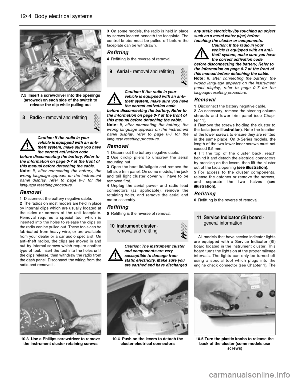
the facia (see illustration). Note the location
of the lower screws to ensure they are refitted
in the same place. On 3-Series models, the
length of the two lower inner screws must not
exceed 9.5 mm.
4Tilt the top of the cluster back, reach
behind it and detach the electrical connectors
by pressing on the levers, then lift the cluster
out of the facia opening (see illustration).
5For access to the cluster components,
release the catches or remove the screws,
and separate the two halves (see
illustration).
Refitting
6Refitting is the reverse of removal.
11 Service Indicator (SI) board-
general information
All models that have service indicator lights
are equipped with a Service Indicator (SI)
board located in the instrument cluster. This
board turns the lights on at the proper mileage
intervals. The lights can only be turned off
using a special tool which plugs into the
engine check connector (see Chapter 1). The
12•4 Body electrical systems
10.5 Turn the plastic knobs to release the
back of the cluster (some models use
screws)10.4 Push on the levers to detach the
cluster electrical connectors10.3 Use a Phillips screwdriver to remove
the instrument cluster retaining screws
7.5 Insert a screwdriver into the openings
(arrowed) on each side of the switch to
release the clip while pulling out
Page 173 of 228

SI board is a self-contained computer which
includes a chip and batteries.
The rechargeable SI board nickel cadmium
(nicad) batteries maintain power to the
computer memory in the event of a power
drop (such as during starting) or complete
power loss (such as a dead or disconnected
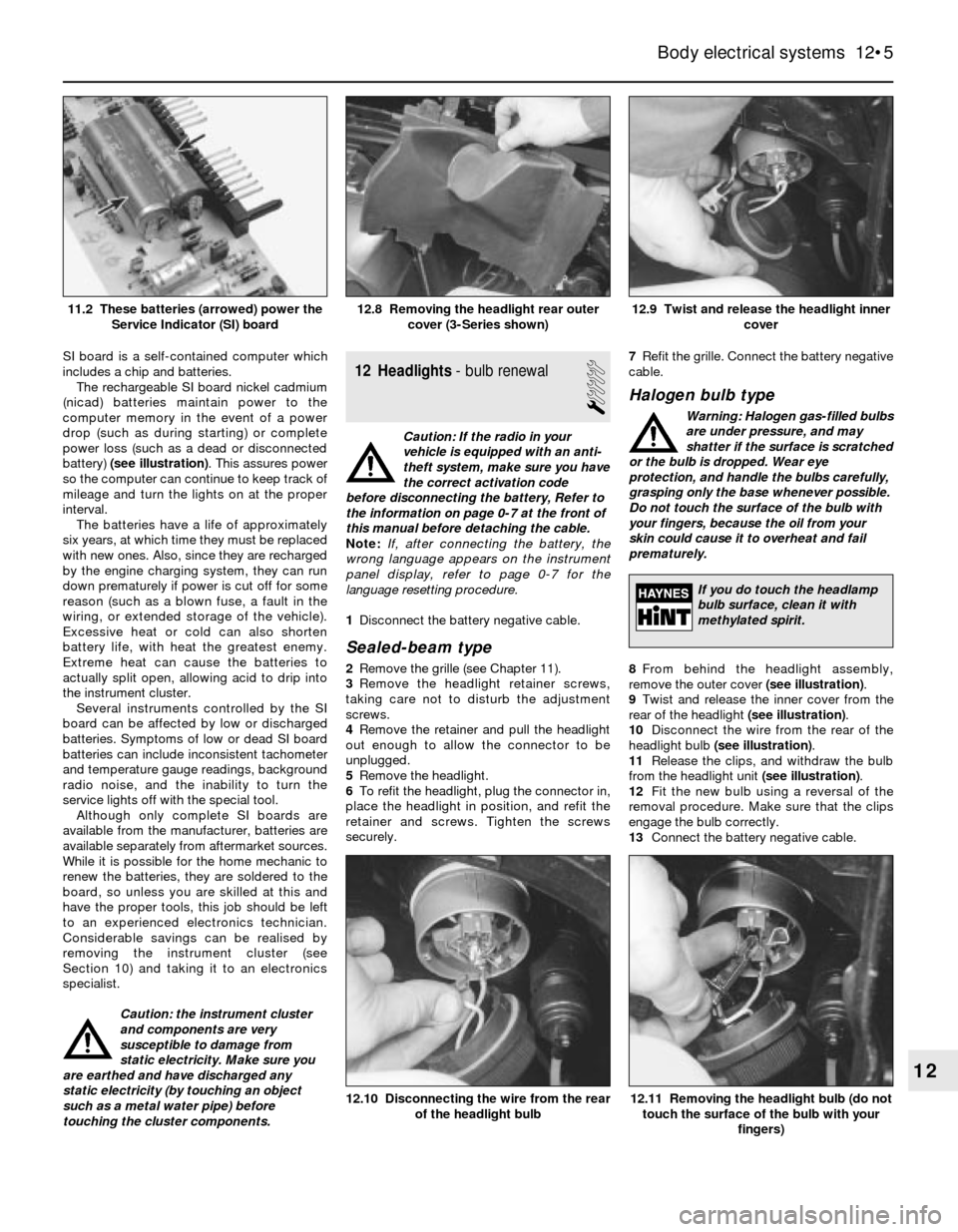
battery) (see illustration). This assures power
so the computer can continue to keep track of
mileage and turn the lights on at the proper
interval.
The batteries have a life of approximately
six years, at which time they must be replaced
with new ones. Also, since they are recharged
by the engine charging system, they can run
down prematurely if power is cut off for some
reason (such as a blown fuse, a fault in the
wiring, or extended storage of the vehicle).
Excessive heat or cold can also shorten
battery life, with heat the greatest enemy.
Extreme heat can cause the batteries to
actually split open, allowing acid to drip into
the instrument cluster.
Several instruments controlled by the SI
board can be affected by low or discharged
batteries. Symptoms of low or dead SI board
batteries can include inconsistent tachometer
and temperature gauge readings, background
radio noise, and the inability to turn the
service lights off with the special tool.
Although only complete SI boards are
available from the manufacturer, batteries are
available separately from aftermarket sources.
While it is possible for the home mechanic to
renew the batteries, they are soldered to the
board, so unless you are skilled at this and
have the proper tools, this job should be left
to an experienced electronics technician.
Considerable savings can be realised by
removing the instrument cluster (see
Section 10) and taking it to an electronics
specialist.
Caution: the instrument cluster
and components are very
susceptible to damage from
static electricity. Make sure you
are earthed and have discharged any
static electricity (by touching an object
such as a metal water pipe) before
touching the cluster components.12 Headlights- bulb renewal
1
Caution: If the radio in your
vehicle is equipped with an anti-
theft system, make sure you have
the correct activation code
before disconnecting the battery, Refer to
the information on page 0-7 at the front of
this manual before detaching the cable.
Note: If, after connecting the battery, the
wrong language appears on the instrument
panel display, refer to page 0-7 for the
language resetting procedure.
1Disconnect the battery negative cable.
Sealed-beam type
2Remove the grille (see Chapter 11).
3Remove the headlight retainer screws,
taking care not to disturb the adjustment
screws.
4Remove the retainer and pull the headlight
out enough to allow the connector to be
unplugged.
5Remove the headlight.
6To refit the headlight, plug the connector in,
place the headlight in position, and refit the
retainer and screws. Tighten the screws
securely.7Refit the grille. Connect the battery negative
cable.
Halogen bulb type
Warning: Halogen gas-filled bulbs
are under pressure, and may
shatter if the surface is scratched
or the bulb is dropped. Wear eye
protection, and handle the bulbs carefully,
grasping only the base whenever possible.
Do not touch the surface of the bulb with
your fingers, because the oil from your
skin could cause it to overheat and fail
prematurely.
8From behind the headlight assembly,
remove the outer cover (see illustration).
9Twist and release the inner cover from the
rear of the headlight (see illustration).
10Disconnect the wire from the rear of the
headlight bulb (see illustration).
11Release the clips, and withdraw the bulb
from the headlight unit (see illustration).
12Fit the new bulb using a reversal of the
removal procedure. Make sure that the clips
engage the bulb correctly.
13Connect the battery negative cable.
Body electrical systems 12•5
12.9 Twist and release the headlight inner
cover12.8 Removing the headlight rear outer
cover (3-Series shown)11.2 These batteries (arrowed) power the
Service Indicator (SI) board
12.11 Removing the headlight bulb (do not
touch the surface of the bulb with your
fingers)12.10 Disconnecting the wire from the rear
of the headlight bulb
12
If you do touch the headlamp
bulb surface, clean it with
methylated spirit.