compression ratio BMW 3 SERIES 1991 E30 User Guide
[x] Cancel search | Manufacturer: BMW, Model Year: 1991, Model line: 3 SERIES, Model: BMW 3 SERIES 1991 E30Pages: 228, PDF Size: 7.04 MB
Page 114 of 228
7 Ignition timing (TCI system)-
check and adjustment
4
Warning: Keep hands, equipment
and wires well clear of the
viscous cooling fan during
adjustment of the ignition timing.
Note:This Section describes the procedure
for checking and adjusting the ignition timing
on engines fitted with the TCI system. On
engines fitted with the Motronic engine
management system, the ignition timing is
controlled by the electronic control unit, and
no adjustment is possible. The timing can be
checked using the following procedure, but no
ignition timing values were available at the
time of writing. If the timing is thought to be
incorrect, refer to a BMW dealer.
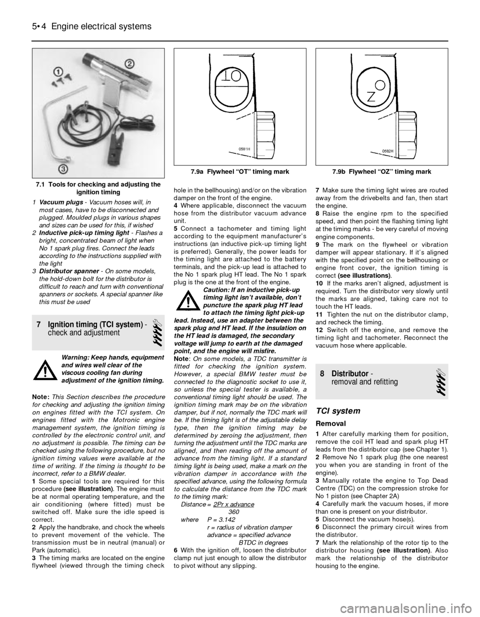
1Some special tools are required for this
procedure (see illustration). The engine must
be at normal operating temperature, and the
air conditioning (where fitted) must be
switched off. Make sure the idle speed is
correct.
2Apply the handbrake, and chock the wheels
to prevent movement of the vehicle. The
transmission must be in neutral (manual) or
Park (automatic).
3The timing marks are located on the engine
flywheel (viewed through the timing checkhole in the bellhousing) and/or on the vibration
damper on the front of the engine.
4Where applicable, disconnect the vacuum
hose from the distributor vacuum advance
unit.
5Connect a tachometer and timing light
according to the equipment manufacturer’s
instructions (an inductive pick-up timing light
is preferred). Generally, the power leads for
the timing light are attached to the battery
terminals, and the pick-up lead is attached to
the No 1 spark plug HT lead. The No 1 spark
plug is the one at the front of the engine.
Caution: If an inductive pick-up
timing light isn’t available, don’t
puncture the spark plug HT lead
to attach the timing light pick-up
lead. Instead, use an adapter between the
spark plug and HT lead. If the insulation on
the HT lead is damaged, the secondary
voltage will jump to earth at the damaged
point, and the engine will misfire.
Note:On some models, a TDC transmitter is
fitted for checking the ignition system.
However, a special BMW tester must be
connected to the diagnostic socket to use it,
so unless the special tester is available, a
conventional timing light should be used. The
ignition timing mark may be on the vibration
damper, but if not, normally the TDC mark will
be. If the timing light is of the adjustable delay
type, then the ignition timing may be
determined by zeroing the adjustment, then
turning the adjustment until the TDC marks are
aligned, and then reading off the amount of
advance from the timing light. If a standard
timing light is being used, make a mark on the
vibration damper in accordance with the
specified advance, using the following formula
to calculate the distance from the TDC mark
to the timing mark:
Distance = 2Pr x advance
360
where P = 3.142
r = radius of vibration damper
advance = specified advance
BTDC in degrees
6With the ignition off, loosen the distributor
clamp nut just enough to allow the distributor
to pivot without any slipping.7Make sure the timing light wires are routed
away from the drivebelts and fan, then start
the engine.
8Raise the engine rpm to the specified
speed, and then point the flashing timing light
at the timing marks - be very careful of moving
engine components.
9The mark on the flywheel or vibration
damper will appear stationary. If it’s aligned
with the specified point on the bellhousing or
engine front cover, the ignition timing is
correct (see illustrations).
10If the marks aren’t aligned, adjustment is
required. Turn the distributor very slowly until
the marks are aligned, taking care not to
touch the HT leads.
11Tighten the nut on the distributor clamp,
and recheck the timing.
12Switch off the engine, and remove the
timing light and tachometer. Reconnect the
vacuum hose where applicable.
8 Distributor-
removal and refitting
4
TCI system
Removal
1After carefully marking them for position,
remove the coil HT lead and spark plug HT
leads from the distributor cap (see Chapter 1).
2Remove No 1 spark plug (the one nearest
you when you are standing in front of the
engine).
3Manually rotate the engine to Top Dead
Centre (TDC) on the compression stroke for
No 1 piston (see Chapter 2A)
4Carefully mark the vacuum hoses, if more
than one is present on your distributor.
5Disconnect the vacuum hose(s).
6Disconnect the primary circuit wires from
the distributor.
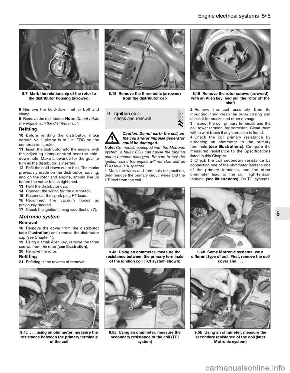
7Mark the relationship of the rotor tip to the
distributor housing (see illustration). Also
mark the relationship of the distributor
housing to the engine.
5•4 Engine electrical systems
7.1 Tools for checking and adjusting the
ignition timing
1Vacuum plugs- Vacuum hoses will, in
most cases, have to be disconnected and
plugged. Moulded plugs in various shapes
and sizes can be used for this, if wished
2Inductive pick-up timing light- Flashes a
bright, concentrated beam of light when
No 1 spark plug fires. Connect the leads
according to the instructions supplied with
the light
3Distributor spanner - On some models,
the hold-down bolt for the distributor is
difficult to reach and turn with conventional
spanners or sockets. A special spanner like
this must be used
7.9a Flywheel “OT” timing mark 7.9b Flywheel “OZ” timing mark
Page 115 of 228
8Remove the hold-down nut or bolt and
clamp.
9Remove the distributor. Note:Do not rotate
the engine with the distributor out.
Refitting
10Before refitting the distributor, make
certain No 1 piston is still at TDC on the
compression stroke.
11Insert the distributor into the engine, with
the adjusting clamp centred over the hold-
down hole. Make allowance for the gear to
turn as the distributor is inserted.
12Refit the hold-down nut or bolt. The marks
previously made on the distributor housing,
and on the rotor and engine, should line up
before the nut or bolt is tightened.
13Refit the distributor cap.
14Connect the wiring for the distributor.
15Reconnect the spark plug HT leads.
16Reconnect the vacuum hoses as
previously marked.
17Check the ignition timing (see Section 7).
Motronic system
Removal
18Remove the cover from the distributor
(see illustration)and remove the distributor
cap (see Chapter 1).
19Using a small Allen key, remove the three
screws from the rotor (see illustration).
20Remove the rotor.
Refitting
21Refitting is the reverse of removal.
9 Ignition coil -
check and renewal
2
Caution: Do not earth the coil, as
the coil and/or impulse generator
could be damaged.
Note:On models equipped with the Motronic
system, a faulty ECU can cause the ignition
coil to become damaged. Be sure to test the
ignition coil if the engine will not start and an
ECU fault is suspected.
1Mark the wires and terminals for position,
then remove the primary circuit wires and the
HT lead from the coil.2Remove the coil assembly from its
mounting, then clean the outer casing and
check it for cracks and other damage.
3Inspect the coil primary terminals and the
coil tower terminal for corrosion. Clean them
with a wire brush if any corrosion is found.
4Check the coil primary resistance by
attaching an ohmmeter to the primary
terminals (see illustrations). Compare the
measured resistance to the Specifications
listed in this Chapter.
5Check the coil secondary resistance by
connecting one of the ohmmeter leads to one
of the primary terminals, and the other
ohmmeter lead to the coil high-tension
terminal (see illustrations). On TCI systems,
Engine electrical systems 5•5
8.19 Remove the rotor screws (arrowed)
with an Allen key, and pull the rotor off the
shaft8.18 Remove the three bolts (arrowed)
from the distributor cap8.7 Mark the relationship of the rotor to
the distributor housing (arrowed)
9.5b Using an ohmmeter, measure the
secondary resistance of the coil (later
Motronic system)9.5a Using an ohmmeter, measure the
secondary resistance of the coil (TCI
system)
9.4b Some Motronic systems use a
different type of coil. First, remove the coil
cover and . . .9.4a Using an ohmmeter, measure the
resistance between the primary terminals
of the ignition coil (TCI system shown)
9.4c . . . using an ohmmeter, measure the
resistance between the primary terminals
of the coil
5
Page 208 of 228
REF•7
REF
Tools and Working Facilities
MImpact screwdriver
MMicrometer and/or vernier calipers (see
illustrations)
MDial gauge (see illustration)
MUniversal electrical multi-meter
MCylinder compression gauge
(see illustration)
MClutch plate alignment set (see illustration)
MBrake shoe steady spring cup removal tool
(see illustration)
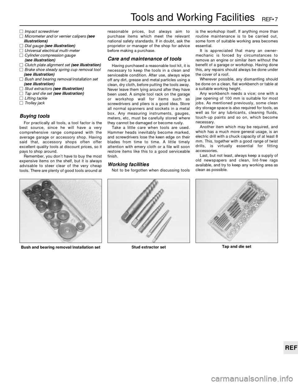
MBush and bearing removal/installation set
(see illustration)
MStud extractors (see illustration)
MTap and die set (see illustration)
MLifting tackle
MTrolley jack
Buying tools
For practically all tools, a tool factor is the
best source, since he will have a very
comprehensive range compared with the
average garage or accessory shop. Having
said that, accessory shops often offer
excellent quality tools at discount prices, so it
pays to shop around.
Remember, you don’t have to buy the most
expensive items on the shelf, but it is always
advisable to steer clear of the very cheap
tools. There are plenty of good tools around atreasonable prices, but always aim to
purchase items which meet the relevant
national safety standards. If in doubt, ask the
proprietor or manager of the shop for advice
before making a purchase.
Care and maintenance of tools
Having purchased a reasonable tool kit, it is
necessary to keep the tools in a clean and
serviceable condition. After use, always wipe
off any dirt, grease and metal particles using a
clean, dry cloth, before putting the tools away.
Never leave them lying around after they have
been used. A simple tool rack on the garage
or workshop wall for items such as
screwdrivers and pliers is a good idea. Store
all normal spanners and sockets in a metal
box. Any measuring instruments, gauges,
meters, etc, must be carefully stored where
they cannot be damaged or become rusty.
Take a little care when tools are used.
Hammer heads inevitably become marked,
and screwdrivers lose the keen edge on their
blades from time to time. A little timely
attention with emery cloth or a file will soon
restore items like this to a good serviceable
finish.
Working facilities
Not to be forgotten when discussing toolsis the workshop itself. If anything more than
routine maintenance is to be carried out,
some form of suitable working area becomes
essential.
It is appreciated that many an owner-
mechanic is forced by circumstances to
remove an engine or similar item without the
benefit of a garage or workshop. Having done
this, any repairs should always be done under
the cover of a roof.
Wherever possible, any dismantling should
be done on a clean, flat workbench or table at
a suitable working height.
Any workbench needs a vice; one with a
jaw opening of 100 mm is suitable for most
jobs. As mentioned previously, some clean
dry storage space is also required for tools, as
well as for any lubricants, cleaning fluids,
touch-up paints and so on, which become
necessary.
Another item which may be required, and
which has a much more general usage, is an
electric drill with a chuck capacity of at least 8
mm. This, together with a good range of twist
drills, is virtually essential for fitting
accessories.
Last, but not least, always keep a supply of
old newspapers and clean, lint-free rags
available, and try to keep any working area as
clean as possible.
Bush and bearing removal/installation setStud extractor setTap and die set
Page 212 of 228
REF•11
REF
Fault Finding
Engine misses at idle speed
m mSpark plugs worn or incorrectly-gapped (Chapter 1).
m mFaulty spark plug HT leads (Chapter 1).
m mVacuum leaks (Chapter 1).
m mIncorrect ignition timing (Chapter 5).
m mUneven or low compression (Chapter 2).
m mFaulty charcoal canister, where fitted (Chapter 6).
Engine misses throughout driving speed range
m
mFuel filter clogged and/or impurities in the fuel system (Chapter 1).
m mLow fuel output at the injectors, or partially-blocked carburettor
jets (Chapter 4).
m mFaulty or incorrectly-gapped spark plugs (Chapter 1).
m mIncorrect ignition timing (Chapter 5).
m mCracked distributor cap, disconnected distributor HT leads, or
damaged distributor components (Chapter 1).
m mFaulty spark plug HT leads (Chapter 1).
m mFaulty emission system components (Chapter 6).
m mLow or uneven cylinder compression pressures (Chapter 2).
m mWeak or faulty ignition system (Chapter 5).
m mVacuum leak in fuel injection system, intake manifold or vacuum
hoses (Chapter 4).
Engine misfires on acceleration
m mSpark plugs fouled (Chapter 1).
m mFuel injection system or carburettor malfunctioning (Chapter 4).
m mFuel filter clogged (Chapters 1 and 4).
m mIncorrect ignition timing (Chapter 5).
m mIntake manifold air leak (Chapter 4).
Engine surges while holding accelerator steady
m
mIntake air leak (Chapter 4).
m mFuel pump faulty (Chapter 4).
m mLoose fuel injector harness connections (Chapters 4 and 6).
m mDefective ECU (Chapter 5).
Engine lacks power
m
mIncorrect ignition timing (Chapter 5).
m mExcessive play in distributor shaft (Chapter 5).
m mWorn rotor, distributor cap or HT leads (Chapters 1 and 5).
m mFaulty or incorrectly-gapped spark plugs (Chapter 1).
m mFuel injection system or carburettor malfunctioning (Chapter 4).
m mFaulty coil (Chapter 5).
m mBrakes binding (Chapter 1).
m mAutomatic transmission fluid level incorrect (Chapter 1).
m mClutch slipping (Chapter 8).
m mFuel filter clogged and/or impurities in the fuel system (Chapter 1).
m mEmission control system not functioning properly (Chapter 6).
m mLow or uneven cylinder compression pressures (Chapter 2).
Engine stalls
m
mIdle speed incorrect (Chapter 1).
m mFuel filter clogged and/or water and impurities in the fuel system
(Chapter 1).
m mDistributor components damp or damaged (Chapter 5).
m mFaulty emissions system components (Chapter 6).
m mFaulty or incorrectly-gapped spark plugs (Chapter 1).
m mFaulty spark plug HT leads (Chapter 1).
m mVacuum leak in the fuel injection system, intake manifold or
vacuum hoses (Chapter 4).
Engine backfires
m mEmissions system not functioning properly (Chapter 6).
m mIgnition timing incorrect (Chapter 5).
m mFaulty secondary ignition system (cracked spark plug insulator,
faulty plug HT leads, distributor cap and/or rotor) (Chapters 1 and 5).
m mFuel injection system or carburettor malfunctioning (Chapter 4).
m mVacuum leak at fuel injector(s), intake manifold or vacuum hoses
(Chapter 4).
m mValve clearances incorrect (Chapter 1), or valve(s) sticking or
damaged (Chapter 2).
Pinking or knocking engine sounds when
accelerating or driving uphill
m mIncorrect grade of fuel.
m mIgnition timing incorrect (Chapter 5).
m mFuel injection system or carburettor in need of adjustment (Chap-
ter 4).
m mDamaged spark plugs or HT leads, or incorrect type fitted (Chapter 1).
m mWorn or damaged distributor components (Chapter 5).
m mFaulty emission system (Chapter 6).
m mVacuum leak (Chapter 4).
Engine runs with oil pressure light on
Caution: Stop the engine immediately if the oil
pressure light comes on and establish the cause.
Running the engine while the oil pressure is low can
cause severe damage.
m mLow oil level (Chapter 1).
m mIdle speed too low (Chapter 1).
m mShort-circuit in wiring (Chapter 12).
m mFaulty oil pressure sender unit (Chapter 2).
m mWorn engine bearings and/or oil pump (Chapter 2).
Engine runs-on after switching off
m
mIdle speed too high (Chapter 1).
m mExcessive engine operating temperature (Chapter 3).
m mIncorrect fuel octane grade.
m mSpark plugs defective or incorrect grade (Chapter 1).
Engine electrical system
Battery will not hold charge
m
mAlternator drivebelt defective or not adjusted properly (Chapter 1).
m mElectrolyte level low (Chapter 1).
m mBattery terminals loose or corroded (Chapter 1).
m mAlternator not charging properly (Chapter 5).
m mLoose, broken or faulty wiring in the charging circuit (Chapter 5).
m mShort in vehicle wiring (Chapters 5 and 12).
m mInternally-defective battery (Chapters 1 and 5).
m mIgnition (no-charge) warning light bulb blown - on some early
models (Chapter 5)
Ignition (no-charge) warning light fails to go out
m mFaulty alternator or charging circuit (Chapter 5).
m mAlternator drivebelt defective or out of adjustment (Chapter 1).
m mAlternator voltage regulator inoperative (Chapter 5).
Ignition (no-charge) warning light fails to come on
when key is turned
m mWarning light bulb defective (Chapter 12).
m mFault in the printed circuit, wiring or bulbholder (Chapter 12).
Page 221 of 228
REF•21
REF
Glossary of Technical Terms
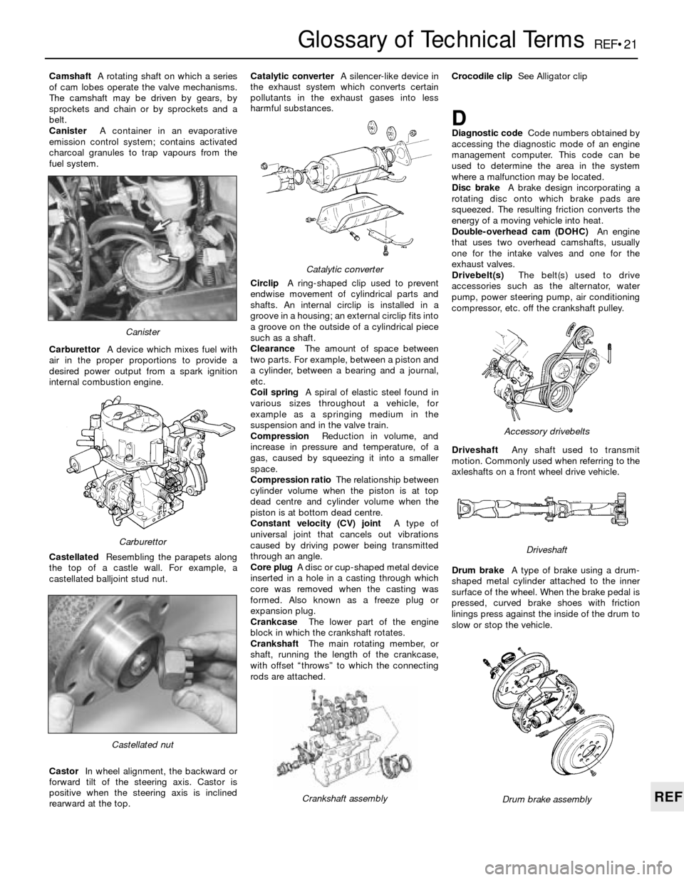
CamshaftA rotating shaft on which a series
of cam lobes operate the valve mechanisms.
The camshaft may be driven by gears, by
sprockets and chain or by sprockets and a
belt.
CanisterA container in an evaporative
emission control system; contains activated
charcoal granules to trap vapours from the
fuel system.
CarburettorA device which mixes fuel with
air in the proper proportions to provide a
desired power output from a spark ignition
internal combustion engine.
CastellatedResembling the parapets along
the top of a castle wall. For example, a
castellated balljoint stud nut.
CastorIn wheel alignment, the backward or
forward tilt of the steering axis. Castor is
positive when the steering axis is inclined
rearward at the top.Catalytic converterA silencer-like device in
the exhaust system which converts certain
pollutants in the exhaust gases into less
harmful substances.
CirclipA ring-shaped clip used to prevent
endwise movement of cylindrical parts and
shafts. An internal circlip is installed in a
groove in a housing; an external circlip fits into
a groove on the outside of a cylindrical piece
such as a shaft.
ClearanceThe amount of space between
two parts. For example, between a piston and
a cylinder, between a bearing and a journal,
etc.
Coil springA spiral of elastic steel found in
various sizes throughout a vehicle, for
example as a springing medium in the
suspension and in the valve train.
CompressionReduction in volume, and
increase in pressure and temperature, of a
gas, caused by squeezing it into a smaller
space.
Compression ratioThe relationship between
cylinder volume when the piston is at top
dead centre and cylinder volume when the
piston is at bottom dead centre.
Constant velocity (CV) jointA type of
universal joint that cancels out vibrations
caused by driving power being transmitted
through an angle.
Core plugA disc or cup-shaped metal device
inserted in a hole in a casting through which
core was removed when the casting was
formed. Also known as a freeze plug or
expansion plug.
CrankcaseThe lower part of the engine
block in which the crankshaft rotates.
CrankshaftThe main rotating member, or
shaft, running the length of the crankcase,
with offset “throws” to which the connecting
rods are attached.Crocodile clipSee Alligator clip
DDiagnostic codeCode numbers obtained by
accessing the diagnostic mode of an engine
management computer. This code can be
used to determine the area in the system
where a malfunction may be located.
Disc brakeA brake design incorporating a
rotating disc onto which brake pads are
squeezed. The resulting friction converts the
energy of a moving vehicle into heat.
Double-overhead cam (DOHC)An engine
that uses two overhead camshafts, usually
one for the intake valves and one for the
exhaust valves.
Drivebelt(s)The belt(s) used to drive
accessories such as the alternator, water
pump, power steering pump, air conditioning
compressor, etc. off the crankshaft pulley.
DriveshaftAny shaft used to transmit
motion. Commonly used when referring to the
axleshafts on a front wheel drive vehicle.
Drum brakeA type of brake using a drum-
shaped metal cylinder attached to the inner
surface of the wheel. When the brake pedal is
pressed, curved brake shoes with friction
linings press against the inside of the drum to
slow or stop the vehicle.
Castellated nut
Catalytic converter
Crankshaft assembly
Carburettor
Canister
Drum brake assembly
Accessory drivebelts
Driveshaft