stop BMW 3 SERIES 1991 E30 Owner's Manual
[x] Cancel search | Manufacturer: BMW, Model Year: 1991, Model line: 3 SERIES, Model: BMW 3 SERIES 1991 E30Pages: 228, PDF Size: 7.04 MB
Page 162 of 228
it to the approximate size and shape required,
then pull off the backing paper (if used) and
stick the tape over the hole; it can be
overlapped if the thickness of one piece is
insufficient. Burnish down the edges of the
tape with the handle of a screwdriver or
similar, to ensure that the tape is securely
attached to the metal underneath.
Bodywork repairs - filling and
respraying
Before using this Section, see the Sections
on dent, deep scratch, rust holes and gash
repairs.
Many types of bodyfiller are available, but
generally speaking, those proprietary kits
which contain a tin of filler paste and a tube of
resin hardener are best for this type of repair. A
wide, flexible plastic or nylon applicator will be
found invaluable for imparting a smooth and
well-contoured finish to the surface of the filler.
Mix up a little filler on a clean piece of card
or board - measure the hardener carefully
(follow the maker’s instructions on the pack),
otherwise the filler will set too rapidly or too
slowly. Using the applicator, apply the filler
paste to the prepared area; draw the
applicator across the surface of the filler to
achieve the correct contour and to level the
surface. As soon as a contour that
approximates to the correct one is achieved,
stop working the paste - if you carry on too
long, the paste will become sticky and begin
to “pick-up” on the applicator. Continue to
add thin layers of filler paste at 20-minute
intervals, until the level of the filler is just
proud of the surrounding bodywork.
Once the filler has hardened, the excess
can be removed using a metal plane or file.
From then on, progressively-finer grades of
abrasive paper should be used, starting with a
40-grade production paper, and finishing with
a 400-grade wet-and-dry paper. Always wrap
the abrasive paper around a flat rubber, cork,
or wooden block - otherwise the surface of
the filler will not be completely flat. During the
smoothing of the filler surface, the wet-and-
dry paper should be periodically rinsed in
water. This will ensure that a very smooth
finish is imparted to the filler at the final stage.
At this stage, the “dent” should be
surrounded by a ring of bare metal, which in
turn should be encircled by the finely
“feathered” edge of the good paintwork.
Rinse the repair area with clean water, until all
of the dust produced by the rubbing-down
operation has gone.
Spray the whole area with a light coat of
primer - this will show up any imperfections in
the surface of the filler. Repair these
imperfections with fresh filler paste or
bodystopper, and once more smooth the
surface with abrasive paper. Repeat this
spray-and-repair procedure until you are
satisfied that the surface of the filler, and the
feathered edge of the paintwork, are perfect.
Clean the repair area with clean water, and
allow to dry fully.The repair area is now ready for final
spraying. Paint spraying must be carried out
in a warm, dry, windless and dust-free
atmosphere. This condition can be created
artificially if you have access to a large indoor
working area, but if you are forced to work in
the open, you will have to pick your day very
carefully. If you are working indoors, dousing
the floor in the work area with water will help
to settle the dust which would otherwise be in
the atmosphere. If the repair area is confined
to one body panel, mask off the surrounding
panels; this will help to minimise the effects of
a slight mis-match in paint colours. Bodywork
fittings (eg chrome strips, door handles etc)
will also need to be masked off. Use genuine
masking tape, and several thicknesses of
newspaper, for the masking operations.
Before commencing to spray, agitate the
aerosol can thoroughly, then spray a test area
(an old tin, or similar) until the technique is
mastered. Cover the repair area with a thick
coat of primer; the thickness should be built
up using several thin layers of paint, rather
than one thick one. Using 400-grade wet-and-
dry paper, rub down the surface of the primer
until it is really smooth. While doing this, the
work area should be thoroughly doused with
water, and the wet-and-dry paper periodically
rinsed in water. Allow to dry before spraying
on more paint.
Spray on the top coat, again building up the
thickness by using several thin layers of paint.
Start spraying at one edge of the repair area,
and then, using a side-to-side motion, work
until the whole repair area and about 2 inches
of the surrounding original paintwork is
covered. Remove all masking material 10 to
15 minutes after spraying on the final coat of
paint.
Allow the new paint at least two weeks to
harden, then, using a paintwork renovator, or
a very fine cutting paste, blend the edges of
the paint into the existing paintwork. Finally,
apply wax polish.
Plastic components
With the use of more and more plastic body
components by the vehicle manufacturers (eg
bumpers. spoilers, and in some cases major
body panels), rectification of more serious
damage to such items has become a matter
of either entrusting repair work to a specialist
in this field, or renewing complete
components. Repair of such damage by the
DIY owner is not really feasible, owing to the
cost of the equipment and materials required
for effecting such repairs. The basic technique
involves making a groove along the line of the
crack in the plastic, using a rotary burr in a
power drill. The damaged part is then weldedback together, using a hot-air gun to heat up
and fuse a plastic filler rod into the groove.
Any excess plastic is then removed, and the
area rubbed down to a smooth finish. It is
important that a filler rod of the correct plastic
is used, as body components can be made of
a variety of different types (eg polycarbonate,
ABS, polypropylene).
Damage of a less serious nature (abrasions,
minor cracks etc) can be repaired by the DIY
owner using a two-part epoxy filler repair
material. Once mixed in equal proportions,
this is used in similar fashion to the bodywork
filler used on metal panels. The filler is usually
cured in twenty to thirty minutes, ready for
sanding and painting.
If the owner is renewing a complete
component himself, or if he has repaired it
with epoxy filler, he will be left with the
problem of finding a suitable paint for finishing
which is compatible with the type of plastic
used. At one time, the use of a universal paint
was not possible, owing to the complex range
of plastics encountered in body component
applications. Standard paints, generally
speaking, will not bond to plastic or rubber
satisfactorily. However, it is now possible to
obtain a plastic body parts finishing kit which
consists of a pre-primer treatment, a primer
and coloured top coat. Full instructions are
normally supplied with a kit, but basically, the
method of use is to first apply the pre-primer
to the component concerned, and allow it to
dry for up to 30 minutes. Then the primer is
applied, and left to dry for about an hour
before finally applying the special-coloured
top coat. The result is a correctly-coloured
component, where the paint will flex with the
plastic or rubber, a property that standard
paint does not normally possess.
6 Bodywork repair-
major damage
5
1Major damage must be repaired by a
qualified bodywork repair specialist, or
preferably by a BMW dealer. Specialised
equipment is required to do the job properly.
2If the damage is extensive, the bodyshell
must be checked for proper alignment, or the
vehicle’s handling characteristics may be
adversely affected and other components
may wear at an accelerated rate.
3Due to the fact that all of the major body
components (bonnet, wings, etc.) are
separate units, any seriously damaged
components should be replaced with new
ones rather than repaired.
Bodywork and fittings 11•3
11
If bodystopper is used, it can
be mixed with cellulose
thinners to form a really thin
paste which is ideal for filling
small holes
Sometimes bodywork
components can be found in
a scrapyard that specialises
in used vehicle components,
often at a considerable saving over the
cost of new parts.
Page 164 of 228
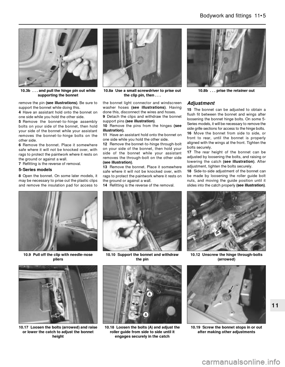
remove the pin (see illustrations). Be sure to
support the bonnet while doing this.
4Have an assistant hold onto the bonnet on
one side while you hold the other side.
5Remove the bonnet-to-hinge assembly
bolts on your side of the bonnet, then hold
your side of the bonnet while your assistant
removes the bonnet-to-hinge bolts on the
other side.
6Remove the bonnet. Place it somewhere
safe where it will not be knocked over, with
rags to protect the paintwork where it rests on
the ground or against a wall.
7Refitting is the reverse of removal.
5-Series models
8Open the bonnet. On some later models, it
may be necessary to prise out the plastic clips
and remove the insulation pad for access tothe bonnet light connector and windscreen
washer hoses (see illustrations). Having
done this, disconnect the wires and hoses.
9Detach the clips and withdraw the bonnet
support pins (see illustration).
10Remove the pins from the hinges (see
illustration).
11Have an assistant hold onto the bonnet on
one side while you hold the other side.
12Remove the bonnet-to-hinge through-bolt
on your side of the bonnet, then hold your
side of the bonnet while your assistant
removes the through-bolt on the other side
(see illustration).
13Remove the bonnet. Place it somewhere
safe where it will not be knocked over, with
rags to protect the paintwork where it rests on
the ground or against a wall.
14Refitting is the reverse of the removal.
Adjustment
15The bonnet can be adjusted to obtain a
flush fit between the bonnet and wings after
loosening the bonnet hinge bolts. On some 5-
Series models, it will be necessary to remove the
side grille sections for access to the hinge bolts.
16Move the bonnet from side to side, or
front to rear, until the bonnet is properly
aligned with the wings at the front. Tighten the
bolts securely.
17The rear height of the bonnet can be
adjusted by loosening the bolts, and raising or
lowering the catch (see illustration). After
adjustment, tighten the bolts securely.
18Side-to-side adjustment of the bonnet can
be made by loosening the roller guide bolt
nuts, and moving the guide position until it
slides into the catch properly (see illustration).
Bodywork and fittings 11•5
10.8b . . . prise the retainer out10.8a Use a small screwdriver to prise out
the clip pin, then . . .10.3b . . . and pull the hinge pin out while
supporting the bonnet
10.19 Screw the bonnet stops in or out
after making other adjustments10.18 Loosen the bolts (A) and adjust the
roller guide from side to side until it
engages securely in the catch10.17 Loosen the bolts (arrowed) and raise
or lower the catch to adjust the bonnet
height
10.12 Unscrew the hinge through-bolts
(arrowed)10.10 Support the bonnet and withdraw
the pin10.9 Pull off the clip with needle-nose
pliers
11
Page 165 of 228
19After adjustment, screw the stop pads in
or out to support the bonnet in its new
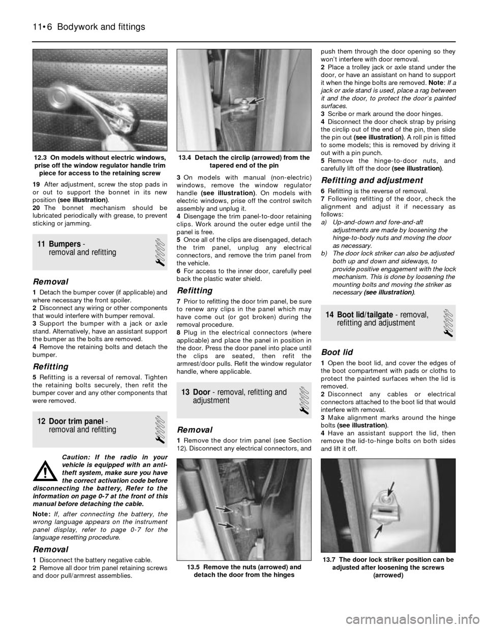
position (see illustration).
20The bonnet mechanism should be
lubricated periodically with grease, to prevent
sticking or jamming.
11 Bumpers-
removal and refitting
1
Removal
1Detach the bumper cover (if applicable) and
where necessary the front spoiler.
2Disconnect any wiring or other components
that would interfere with bumper removal.
3Support the bumper with a jack or axle
stand. Alternatively, have an assistant support
the bumper as the bolts are removed.
4Remove the retaining bolts and detach the
bumper.
Refitting
5Refitting is a reversal of removal. Tighten
the retaining bolts securely, then refit the
bumper cover and any other components that
were removed.
12 Door trim panel-
removal and refitting
1
Caution: If the radio in your
vehicle is equipped with an anti-
theft system, make sure you have
the correct activation code before
disconnecting the battery, Refer to the
information on page 0-7 at the front of this
manual before detaching the cable.
Note: If, after connecting the battery, the
wrong language appears on the instrument
panel display, refer to page 0-7 for the
language resetting procedure.
Removal
1Disconnect the battery negative cable.
2Remove all door trim panel retaining screws
and door pull/armrest assemblies.3On models with manual (non-electric)
windows, remove the window regulator
handle (see illustration). On models with
electric windows, prise off the control switch
assembly and unplug it.
4Disengage the trim panel-to-door retaining
clips. Work around the outer edge until the
panel is free.
5Once all of the clips are disengaged, detach
the trim panel, unplug any electrical
connectors, and remove the trim panel from
the vehicle.
6For access to the inner door, carefully peel
back the plastic water shield.
Refitting
7Prior to refitting the door trim panel, be sure
to renew any clips in the panel which may
have come out (or got broken) during the
removal procedure.
8Plug in the electrical connectors (where
applicable) and place the panel in position in
the door. Press the door panel into place until
the clips are seated, then refit the
armrest/door pulls. Refit the window regulator
handle, where applicable.
13 Door- removal, refitting and
adjustment
1
Removal
1Remove the door trim panel (see Section
12). Disconnect any electrical connectors, andpush them through the door opening so they
won’t interfere with door removal.
2Place a trolley jack or axle stand under the
door, or have an assistant on hand to support
it when the hinge bolts are removed. Note: If a
jack or axle stand is used, place a rag between
it and the door, to protect the door’s painted
surfaces.
3Scribe or mark around the door hinges.
4Disconnect the door check strap by prising
the circlip out of the end of the pin, then slide
the pin out (see illustration). A roll pin is fitted
to some models; this is removed by driving it
out with a pin punch.
5Remove the hinge-to-door nuts, and
carefully lift off the door (see illustration).
Refitting and adjustment
6Refitting is the reverse of removal.
7Following refitting of the door, check the
alignment and adjust it if necessary as
follows:
a) Up-and-down and fore-and-aft
adjustments are made by loosening the
hinge-to-body nuts and moving the door
as necessary.
b) The door lock striker can also be adjusted
both up and down and sideways, to
provide positive engagement with the lock
mechanism. This is done by loosening the
mounting bolts and moving the striker as
necessary (see illustration).
14 Boot lid/tailgate- removal,
refitting and adjustment
1
Boot lid
1Open the boot lid, and cover the edges of
the boot compartment with pads or cloths to
protect the painted surfaces when the lid is
removed.
2Disconnect any cables or electrical
connectors attached to the boot lid that would
interfere with removal.
3Make alignment marks around the hinge
bolts (see illustration).
4Have an assistant support the lid, then
remove the lid-to-hinge bolts on both sides
and lift it off.
11•6 Bodywork and fittings
13.7 The door lock striker position can be
adjusted after loosening the screws
(arrowed)13.5 Remove the nuts (arrowed) and
detach the door from the hinges
13.4 Detach the circlip (arrowed) from the
tapered end of the pin12.3 On models without electric windows,
prise off the window regulator handle trim
piece for access to the retaining screw
Page 168 of 228
19 Steering column shrouds -
removal and refitting
1
Caution: If the radio in your
vehicle is equipped with an anti-
theft system, make sure you have
the correct activation code
before disconnecting the battery, Refer to
the information on page 0-7 at the front of
this manual before detaching the cable.
Note: If, after connecting the battery, the
wrong language appears on the instrument
panel display, refer to page 0-7 for the
language resetting procedure.
Removal
1Disconnect the battery negative cable.
2Remove the steering wheel (Chapter 10).
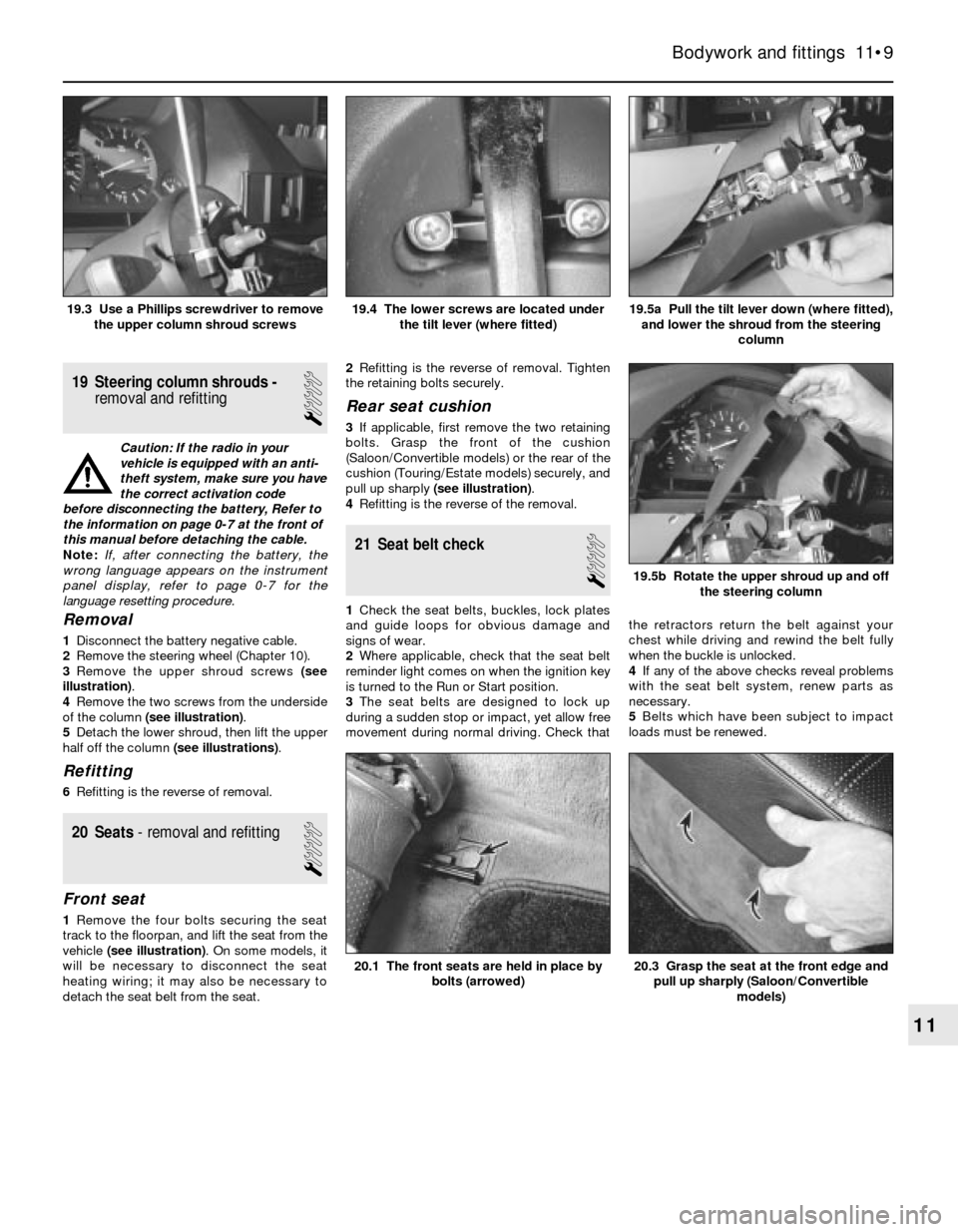
3Remove the upper shroud screws (see
illustration).
4Remove the two screws from the underside
of the column (see illustration).
5Detach the lower shroud, then lift the upper
half off the column (see illustrations).
Refitting
6Refitting is the reverse of removal.
20 Seats- removal and refitting
1
Front seat
1Remove the four bolts securing the seat
track to the floorpan, and lift the seat from the
vehicle (see illustration). On some models, it
will be necessary to disconnect the seat
heating wiring; it may also be necessary to
detach the seat belt from the seat.2Refitting is the reverse of removal. Tighten
the retaining bolts securely.
Rear seat cushion
3If applicable, first remove the two retaining
bolts. Grasp the front of the cushion
(Saloon/Convertible models) or the rear of the
cushion (Touring/Estate models) securely, and
pull up sharply (see illustration).
4Refitting is the reverse of the removal.
21 Seat belt check
1
1Check the seat belts, buckles, lock plates
and guide loops for obvious damage and
signs of wear.
2Where applicable, check that the seat belt
reminder light comes on when the ignition key
is turned to the Run or Start position.
3The seat belts are designed to lock up
during a sudden stop or impact, yet allow free
movement during normal driving. Check thatthe retractors return the belt against your
chest while driving and rewind the belt fully
when the buckle is unlocked.
4If any of the above checks reveal problems
with the seat belt system, renew parts as
necessary.
5Belts which have been subject to impact
loads must be renewed.
Bodywork and fittings 11•9
19.5a Pull the tilt lever down (where fitted),
and lower the shroud from the steering
column19.4 The lower screws are located under
the tilt lever (where fitted)19.3 Use a Phillips screwdriver to remove
the upper column shroud screws
20.3 Grasp the seat at the front edge and
pull up sharply (Saloon/Convertible
models)20.1 The front seats are held in place by
bolts (arrowed)
19.5b Rotate the upper shroud up and off
the steering column
11
Page 180 of 228
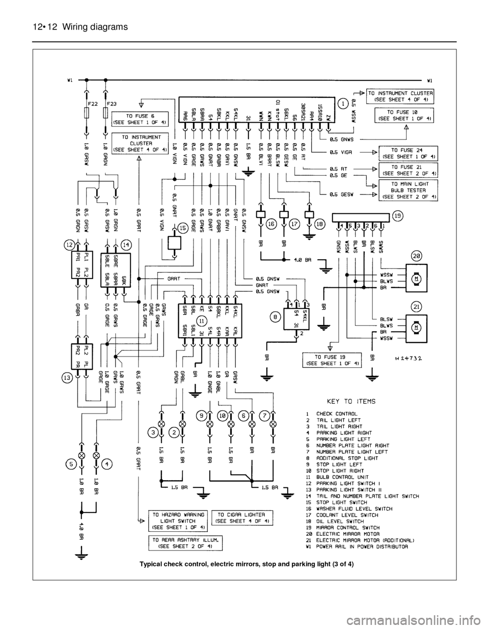
12•12 Wiring diagrams
Typical check control, electric mirrors, stop and parking light (3 of 4)
Page 203 of 228
REF•2MOT Test Checks
Seat belts and seats
Note: The following checks are applicable to
all seat belts, front and rear.
MExamine the webbing of all the belts
(including rear belts if fitted) for cuts, serious
fraying or deterioration. Fasten and unfasten
each belt to check the buckles. If applicable,
check the retracting mechanism. Check the
security of all seat belt mountings accessible
from inside the vehicle.
MThe front seats themselves must be
securely attached and the backrests must
lock in the upright position.
Doors
MBoth front doors must be able to be opened
and closed from outside and inside, and must
latch securely when closed.
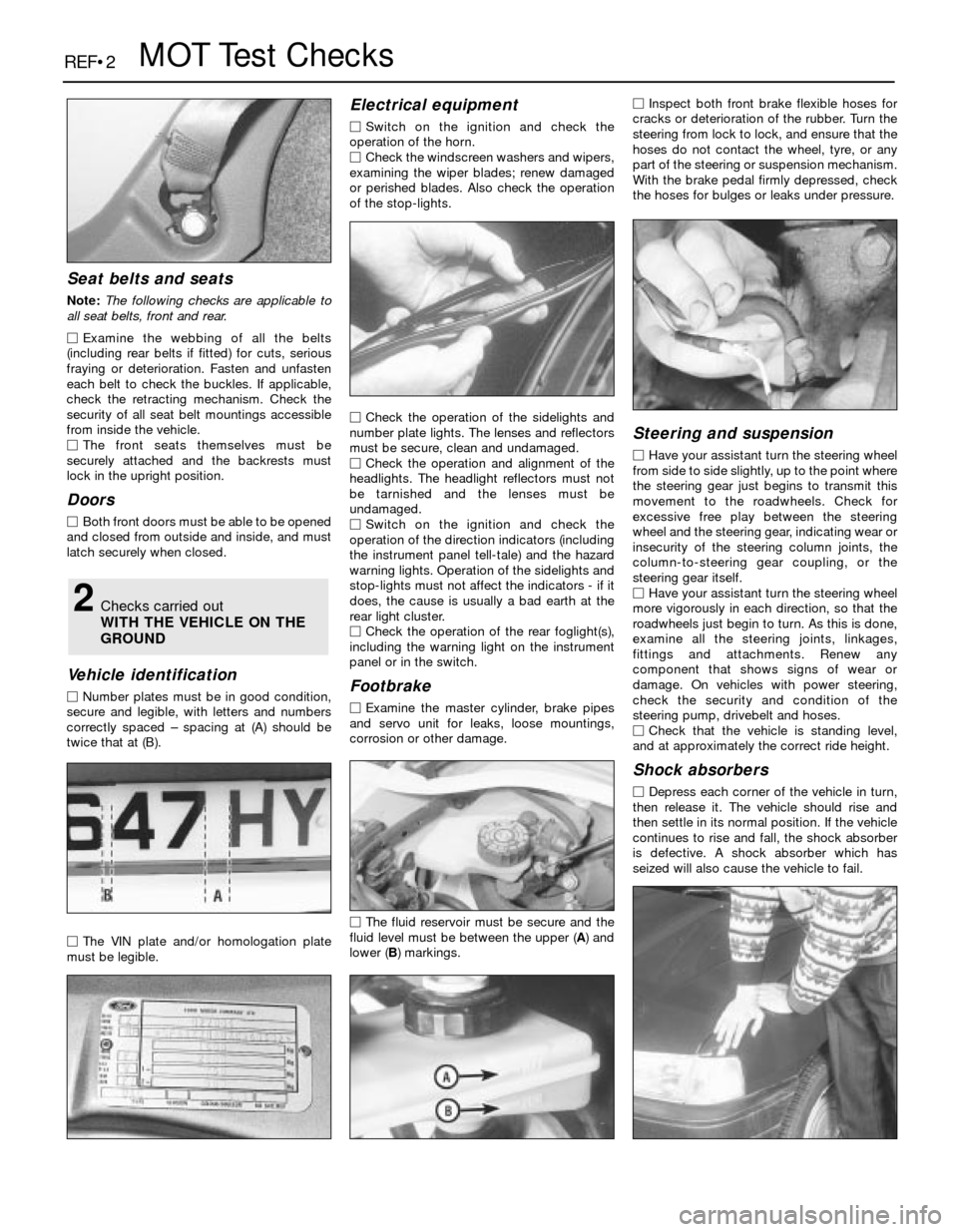
Vehicle identification
MNumber plates must be in good condition,
secure and legible, with letters and numbers
correctly spaced – spacing at (A) should be
twice that at (B).
MThe VIN plate and/or homologation plate
must be legible.
Electrical equipment
MSwitch on the ignition and check the
operation of the horn.
MCheck the windscreen washers and wipers,
examining the wiper blades; renew damaged
or perished blades. Also check the operation
of the stop-lights.
MCheck the operation of the sidelights and
number plate lights. The lenses and reflectors
must be secure, clean and undamaged.
MCheck the operation and alignment of the
headlights. The headlight reflectors must not
be tarnished and the lenses must be
undamaged.
MSwitch on the ignition and check the
operation of the direction indicators (including
the instrument panel tell-tale) and the hazard
warning lights. Operation of the sidelights and
stop-lights must not affect the indicators - if it
does, the cause is usually a bad earth at the
rear light cluster.
MCheck the operation of the rear foglight(s),
including the warning light on the instrument
panel or in the switch.
Footbrake
MExamine the master cylinder, brake pipes
and servo unit for leaks, loose mountings,
corrosion or other damage.
MThe fluid reservoir must be secure and the
fluid level must be between the upper (A) and
lower (B) markings.MInspect both front brake flexible hoses for
cracks or deterioration of the rubber. Turn the
steering from lock to lock, and ensure that the
hoses do not contact the wheel, tyre, or any
part of the steering or suspension mechanism.
With the brake pedal firmly depressed, check
the hoses for bulges or leaks under pressure.
Steering and suspension
MHave your assistant turn the steering wheel
from side to side slightly, up to the point where
the steering gear just begins to transmit this
movement to the roadwheels. Check for
excessive free play between the steering
wheel and the steering gear, indicating wear or
insecurity of the steering column joints, the
column-to-steering gear coupling, or the
steering gear itself.
MHave your assistant turn the steering wheel
more vigorously in each direction, so that the
roadwheels just begin to turn. As this is done,
examine all the steering joints, linkages,
fittings and attachments. Renew any
component that shows signs of wear or
damage. On vehicles with power steering,
check the security and condition of the
steering pump, drivebelt and hoses.
MCheck that the vehicle is standing level,
and at approximately the correct ride height.
Shock absorbers
MDepress each corner of the vehicle in turn,
then release it. The vehicle should rise and
then settle in its normal position. If the vehicle
continues to rise and fall, the shock absorber
is defective. A shock absorber which has
seized will also cause the vehicle to fail.
2Checks carried out
WITH THE VEHICLE ON THE
GROUND
Page 210 of 228
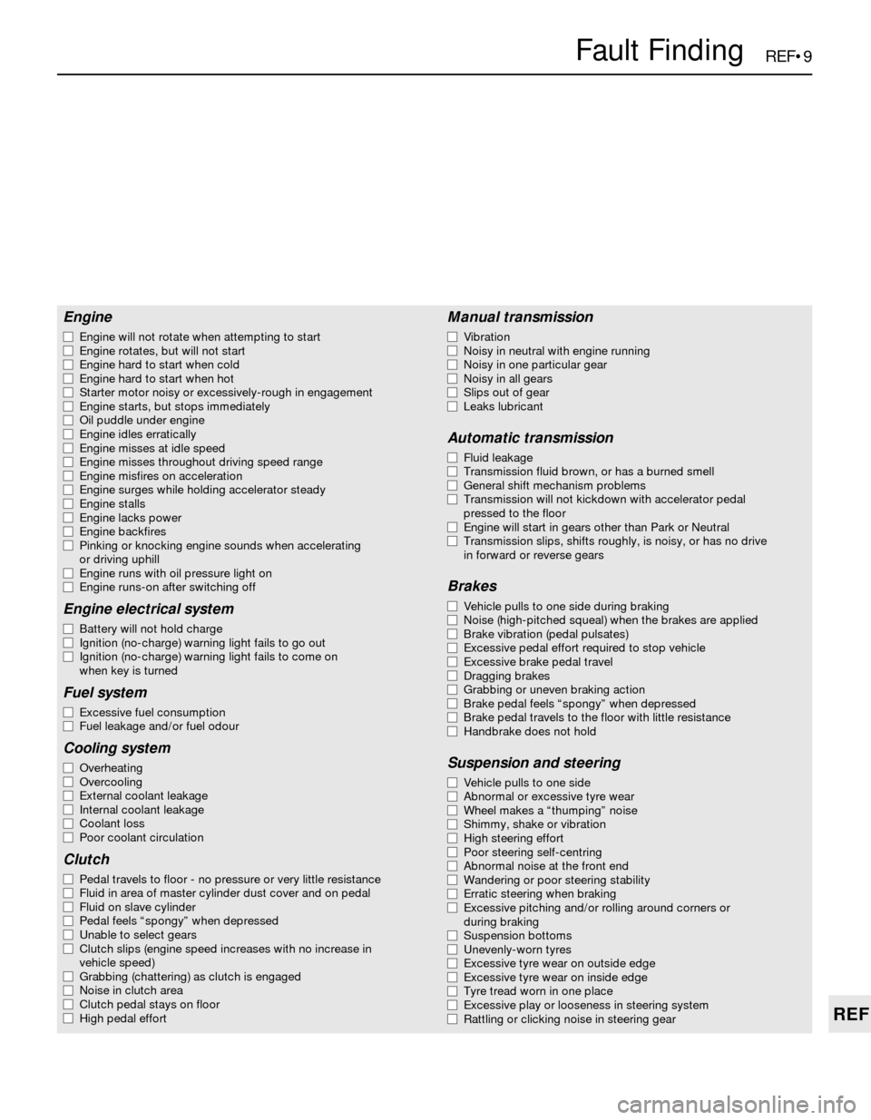
REF•9
REF
Fault Finding
Engine
m mEngine will not rotate when attempting to start
m mEngine rotates, but will not start
m mEngine hard to start when cold
m mEngine hard to start when hot
m mStarter motor noisy or excessively-rough in engagement
m mEngine starts, but stops immediately
m mOil puddle under engine
m mEngine idles erratically
m mEngine misses at idle speed
m mEngine misses throughout driving speed range
m mEngine misfires on acceleration
m mEngine surges while holding accelerator steady
m mEngine stalls
m mEngine lacks power
m mEngine backfires
m mPinking or knocking engine sounds when accelerating
or driving uphill
m mEngine runs with oil pressure light on
m mEngine runs-on after switching off
Engine electrical system
m
mBattery will not hold charge
m mIgnition (no-charge) warning light fails to go out
m mIgnition (no-charge) warning light fails to come on
when key is turned
Fuel system
m mExcessive fuel consumption
m mFuel leakage and/or fuel odour
Cooling system
m
mOverheating
m mOvercooling
m mExternal coolant leakage
m mInternal coolant leakage
m mCoolant loss
m mPoor coolant circulation
Clutch
m
mPedal travels to floor - no pressure or very little resistance
m mFluid in area of master cylinder dust cover and on pedal
m mFluid on slave cylinder
m mPedal feels “spongy” when depressed
m mUnable to select gears
m mClutch slips (engine speed increases with no increase in
vehicle speed)
m mGrabbing (chattering) as clutch is engaged
m mNoise in clutch area
m mClutch pedal stays on floor
m mHigh pedal effort
Manual transmission
m
mVibration
m mNoisy in neutral with engine running
m mNoisy in one particular gear
m mNoisy in all gears
m mSlips out of gear
m mLeaks lubricant
Automatic transmission
m
mFluid leakage
m mTransmission fluid brown, or has a burned smell
m mGeneral shift mechanism problems
m mTransmission will not kickdown with accelerator pedal
pressed to the floor
m mEngine will start in gears other than Park or Neutral
m mTransmission slips, shifts roughly, is noisy, or has no drive
in forward or reverse gears
Brakes
m mVehicle pulls to one side during braking
m mNoise (high-pitched squeal) when the brakes are applied
m mBrake vibration (pedal pulsates)
m mExcessive pedal effort required to stop vehicle
m mExcessive brake pedal travel
m mDragging brakes
m mGrabbing or uneven braking action
m mBrake pedal feels “spongy” when depressed
m mBrake pedal travels to the floor with little resistance
m mHandbrake does not hold
Suspension and steering
m
mVehicle pulls to one side
m mAbnormal or excessive tyre wear
m mWheel makes a “thumping” noise
m mShimmy, shake or vibration
m mHigh steering effort
m mPoor steering self-centring
m mAbnormal noise at the front end
m mWandering or poor steering stability
m mErratic steering when braking
m mExcessive pitching and/or rolling around corners or
during braking
m mSuspension bottoms
m mUnevenly-worn tyres
m mExcessive tyre wear on outside edge
m mExcessive tyre wear on inside edge
m mTyre tread worn in one place
m mExcessive play or looseness in steering system
m mRattling or clicking noise in steering gear
Page 211 of 228
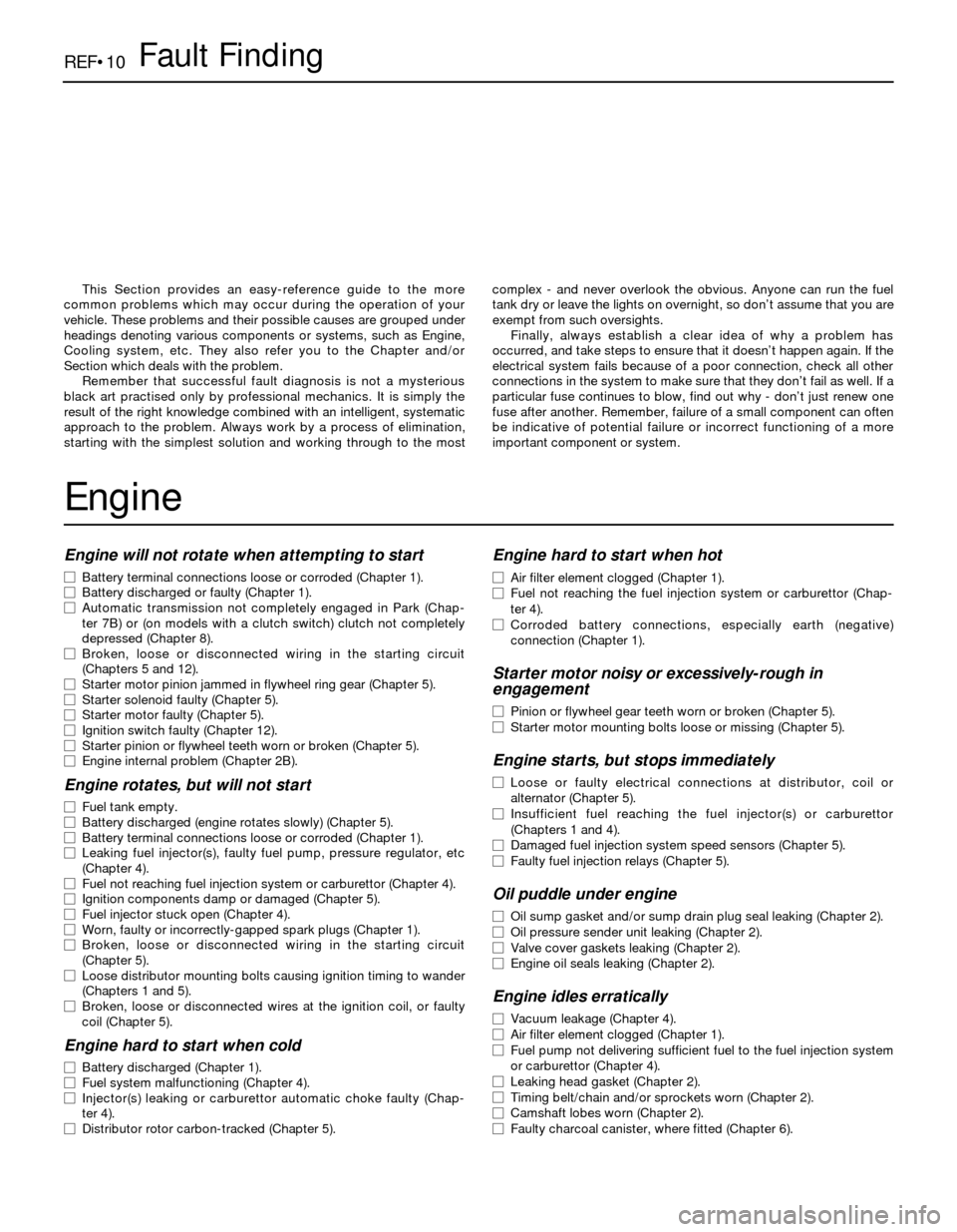
REF•10Fault Finding
Engine will not rotate when attempting to start
m mBattery terminal connections loose or corroded (Chapter 1).
m mBattery discharged or faulty (Chapter 1).
m mAutomatic transmission not completely engaged in Park (Chap-
ter 7B) or (on models with a clutch switch) clutch not completely
depressed (Chapter 8).
m mBroken, loose or disconnected wiring in the starting circuit
(Chapters 5 and 12).
m mStarter motor pinion jammed in flywheel ring gear (Chapter 5).
m mStarter solenoid faulty (Chapter 5).
m mStarter motor faulty (Chapter 5).
m mIgnition switch faulty (Chapter 12).
m mStarter pinion or flywheel teeth worn or broken (Chapter 5).
m mEngine internal problem (Chapter 2B).
Engine rotates, but will not start
m
mFuel tank empty.
m mBattery discharged (engine rotates slowly) (Chapter 5).
m mBattery terminal connections loose or corroded (Chapter 1).
m mLeaking fuel injector(s), faulty fuel pump, pressure regulator, etc
(Chapter 4).
m mFuel not reaching fuel injection system or carburettor (Chapter 4).
m mIgnition components damp or damaged (Chapter 5).
m mFuel injector stuck open (Chapter 4).
m mWorn, faulty or incorrectly-gapped spark plugs (Chapter 1).
m mBroken, loose or disconnected wiring in the starting circuit
(Chapter 5).
m mLoose distributor mounting bolts causing ignition timing to wander
(Chapters 1 and 5).
m mBroken, loose or disconnected wires at the ignition coil, or faulty
coil (Chapter 5).
Engine hard to start when cold
m mBattery discharged (Chapter 1).
m mFuel system malfunctioning (Chapter 4).
m mInjector(s) leaking or carburettor automatic choke faulty (Chap-
ter 4).
m mDistributor rotor carbon-tracked (Chapter 5).
Engine hard to start when hot
m
mAir filter element clogged (Chapter 1).
m mFuel not reaching the fuel injection system or carburettor (Chap-
ter 4).
m mCorroded battery connections, especially earth (negative)
connection (Chapter 1).
Starter motor noisy or excessively-rough in
engagement
m mPinion or flywheel gear teeth worn or broken (Chapter 5).
m mStarter motor mounting bolts loose or missing (Chapter 5).
Engine starts, but stops immediately
m
mLoose or faulty electrical connections at distributor, coil or
alternator (Chapter 5).
m mInsufficient fuel reaching the fuel injector(s) or carburettor
(Chapters 1 and 4).
m mDamaged fuel injection system speed sensors (Chapter 5).
m mFaulty fuel injection relays (Chapter 5).
Oil puddle under engine
m
mOil sump gasket and/or sump drain plug seal leaking (Chapter 2).
m mOil pressure sender unit leaking (Chapter 2).
m mValve cover gaskets leaking (Chapter 2).
m mEngine oil seals leaking (Chapter 2).
Engine idles erratically
m
mVacuum leakage (Chapter 4).
m mAir filter element clogged (Chapter 1).
m mFuel pump not delivering sufficient fuel to the fuel injection system
or carburettor (Chapter 4).
m mLeaking head gasket (Chapter 2).
m mTiming belt/chain and/or sprockets worn (Chapter 2).
m mCamshaft lobes worn (Chapter 2).
m mFaulty charcoal canister, where fitted (Chapter 6). This Section provides an easy-reference guide to the more
common problems which may occur during the operation of your
vehicle. These problems and their possible causes are grouped under
headings denoting various components or systems, such as Engine,
Cooling system, etc. They also refer you to the Chapter and/or
Section which deals with the problem.
Remember that successful fault diagnosis is not a mysterious
black art practised only by professional mechanics. It is simply the
result of the right knowledge combined with an intelligent, systematic
approach to the problem. Always work by a process of elimination,
starting with the simplest solution and working through to the mostcomplex - and never overlook the obvious. Anyone can run the fuel
tank dry or leave the lights on overnight, so don’t assume that you are
exempt from such oversights.
Finally, always establish a clear idea of why a problem has
occurred, and take steps to ensure that it doesn’t happen again. If the
electrical system fails because of a poor connection, check all other
connections in the system to make sure that they don’t fail as well. If a
particular fuse continues to blow, find out why - don’t just renew one
fuse after another. Remember, failure of a small component can often
be indicative of potential failure or incorrect functioning of a more
important component or system.
Engine
Page 212 of 228
REF•11
REF
Fault Finding
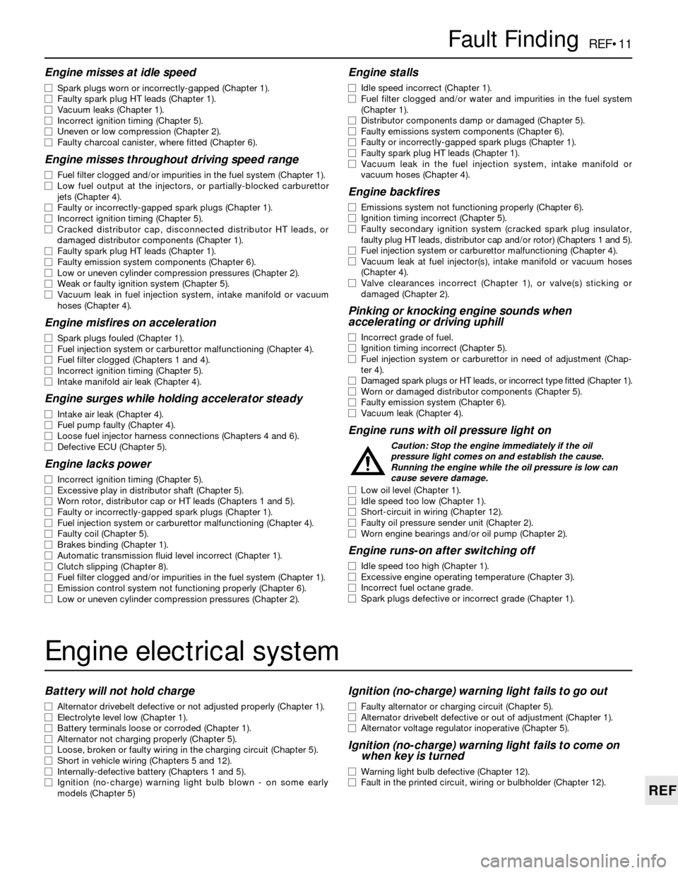
Engine misses at idle speed
m mSpark plugs worn or incorrectly-gapped (Chapter 1).
m mFaulty spark plug HT leads (Chapter 1).
m mVacuum leaks (Chapter 1).
m mIncorrect ignition timing (Chapter 5).
m mUneven or low compression (Chapter 2).
m mFaulty charcoal canister, where fitted (Chapter 6).
Engine misses throughout driving speed range
m
mFuel filter clogged and/or impurities in the fuel system (Chapter 1).
m mLow fuel output at the injectors, or partially-blocked carburettor
jets (Chapter 4).
m mFaulty or incorrectly-gapped spark plugs (Chapter 1).
m mIncorrect ignition timing (Chapter 5).
m mCracked distributor cap, disconnected distributor HT leads, or
damaged distributor components (Chapter 1).
m mFaulty spark plug HT leads (Chapter 1).
m mFaulty emission system components (Chapter 6).
m mLow or uneven cylinder compression pressures (Chapter 2).
m mWeak or faulty ignition system (Chapter 5).
m mVacuum leak in fuel injection system, intake manifold or vacuum
hoses (Chapter 4).
Engine misfires on acceleration
m mSpark plugs fouled (Chapter 1).
m mFuel injection system or carburettor malfunctioning (Chapter 4).
m mFuel filter clogged (Chapters 1 and 4).
m mIncorrect ignition timing (Chapter 5).
m mIntake manifold air leak (Chapter 4).
Engine surges while holding accelerator steady
m
mIntake air leak (Chapter 4).
m mFuel pump faulty (Chapter 4).
m mLoose fuel injector harness connections (Chapters 4 and 6).
m mDefective ECU (Chapter 5).
Engine lacks power
m
mIncorrect ignition timing (Chapter 5).
m mExcessive play in distributor shaft (Chapter 5).
m mWorn rotor, distributor cap or HT leads (Chapters 1 and 5).
m mFaulty or incorrectly-gapped spark plugs (Chapter 1).
m mFuel injection system or carburettor malfunctioning (Chapter 4).
m mFaulty coil (Chapter 5).
m mBrakes binding (Chapter 1).
m mAutomatic transmission fluid level incorrect (Chapter 1).
m mClutch slipping (Chapter 8).
m mFuel filter clogged and/or impurities in the fuel system (Chapter 1).
m mEmission control system not functioning properly (Chapter 6).
m mLow or uneven cylinder compression pressures (Chapter 2).
Engine stalls
m
mIdle speed incorrect (Chapter 1).
m mFuel filter clogged and/or water and impurities in the fuel system
(Chapter 1).
m mDistributor components damp or damaged (Chapter 5).
m mFaulty emissions system components (Chapter 6).
m mFaulty or incorrectly-gapped spark plugs (Chapter 1).
m mFaulty spark plug HT leads (Chapter 1).
m mVacuum leak in the fuel injection system, intake manifold or
vacuum hoses (Chapter 4).
Engine backfires
m mEmissions system not functioning properly (Chapter 6).
m mIgnition timing incorrect (Chapter 5).
m mFaulty secondary ignition system (cracked spark plug insulator,
faulty plug HT leads, distributor cap and/or rotor) (Chapters 1 and 5).
m mFuel injection system or carburettor malfunctioning (Chapter 4).
m mVacuum leak at fuel injector(s), intake manifold or vacuum hoses
(Chapter 4).
m mValve clearances incorrect (Chapter 1), or valve(s) sticking or
damaged (Chapter 2).
Pinking or knocking engine sounds when
accelerating or driving uphill
m mIncorrect grade of fuel.
m mIgnition timing incorrect (Chapter 5).
m mFuel injection system or carburettor in need of adjustment (Chap-
ter 4).
m mDamaged spark plugs or HT leads, or incorrect type fitted (Chapter 1).
m mWorn or damaged distributor components (Chapter 5).
m mFaulty emission system (Chapter 6).
m mVacuum leak (Chapter 4).
Engine runs with oil pressure light on
Caution: Stop the engine immediately if the oil
pressure light comes on and establish the cause.
Running the engine while the oil pressure is low can
cause severe damage.
m mLow oil level (Chapter 1).
m mIdle speed too low (Chapter 1).
m mShort-circuit in wiring (Chapter 12).
m mFaulty oil pressure sender unit (Chapter 2).
m mWorn engine bearings and/or oil pump (Chapter 2).
Engine runs-on after switching off
m
mIdle speed too high (Chapter 1).
m mExcessive engine operating temperature (Chapter 3).
m mIncorrect fuel octane grade.
m mSpark plugs defective or incorrect grade (Chapter 1).
Engine electrical system
Battery will not hold charge
m
mAlternator drivebelt defective or not adjusted properly (Chapter 1).
m mElectrolyte level low (Chapter 1).
m mBattery terminals loose or corroded (Chapter 1).
m mAlternator not charging properly (Chapter 5).
m mLoose, broken or faulty wiring in the charging circuit (Chapter 5).
m mShort in vehicle wiring (Chapters 5 and 12).
m mInternally-defective battery (Chapters 1 and 5).
m mIgnition (no-charge) warning light bulb blown - on some early
models (Chapter 5)
Ignition (no-charge) warning light fails to go out
m mFaulty alternator or charging circuit (Chapter 5).
m mAlternator drivebelt defective or out of adjustment (Chapter 1).
m mAlternator voltage regulator inoperative (Chapter 5).
Ignition (no-charge) warning light fails to come on
when key is turned
m mWarning light bulb defective (Chapter 12).
m mFault in the printed circuit, wiring or bulbholder (Chapter 12).
Page 215 of 228
REF•14Fault Finding
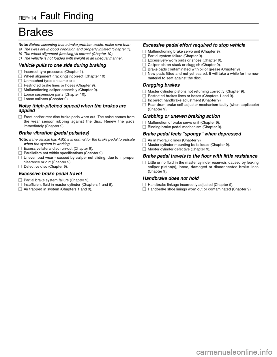
Brakes
Note:Before assuming that a brake problem exists, make sure that:
a) The tyres are in good condition and properly inflated (Chapter 1).
b) The wheel alignment (tracking) is correct (Chapter 10).
c) The vehicle is not loaded with weight in an unequal manner.
Vehicle pulls to one side during braking
m mIncorrect tyre pressures (Chapter 1).
m mWheel alignment (tracking) incorrect (Chapter 10)
m mUnmatched tyres on same axle.
m mRestricted brake lines or hoses (Chapter 9).
m mMalfunctioning caliper assembly (Chapter 9).
m mLoose suspension parts (Chapter 10).
m mLoose calipers (Chapter 9).
Noise (high-pitched squeal) when the brakes are
applied
m mFront and/or rear disc brake pads worn out. The noise comes from
the wear sensor rubbing against the disc. Renew the pads
immediately (Chapter 9).
Brake vibration (pedal pulsates)
Note:If the vehicle has ABS, it is normal for the brake pedal to pulsate
when the system is working.
m mExcessive lateral disc run-out (Chapter 9).
m mParallelism not within specifications (Chapter 9).
m mUneven pad wear - caused by caliper not sliding, due to improper
clearance or dirt (Chapter 9).
m mDefective disc (Chapter 9).
Excessive brake pedal travel
m
mPartial brake system failure (Chapter 9).
m mInsufficient fluid in master cylinder (Chapters 1 and 9).
m mAir trapped in system (Chapters 1 and 9).
Excessive pedal effort required to stop vehicle
m
mMalfunctioning brake servo unit (Chapter 9).
m mPartial system failure (Chapter 9).
m mExcessively-worn pads or shoes (Chapter 9).
m mCaliper piston stuck or sluggish (Chapter 9).
m mBrake pads contaminated with oil or grease (Chapter 9).
m mNew pads fitted and not yet seated. It will take a while for the new
material to seat against the disc.
Dragging brakes
m mMaster cylinder pistons not returning correctly (Chapter 9).
m mRestricted brakes lines or hoses (Chapters 1 and 9).
m mIncorrect handbrake adjustment (Chapter 9).
m mRear drum brake self-adjuster mechanism faulty (when applicable)
(Chapter 9).
Grabbing or uneven braking action
m mMalfunction of brake servo unit (Chapter 9).
m mBinding brake pedal mechanism (Chapter 9).
Brake pedal feels “spongy” when depressed
m
mAir in hydraulic lines (Chapter 9).
m mMaster cylinder mounting bolts loose (Chapter 9).
m mMaster cylinder defective (Chapter 9).
Brake pedal travels to the floor with little resistance
m
mLittle or no fluid in the master cylinder reservoir, caused by leaking
caliper piston(s), loose, damaged or disconnected brake lines
(Chapter 9).
Handbrake does not hold
m mHandbrake linkage incorrectly adjusted (Chapter 9).
m mHandbrake shoe linings worn out or contaminated (Chapter 9).