stop BMW 3 SERIES 1991 E30 User Guide
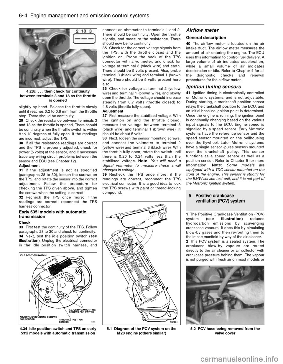
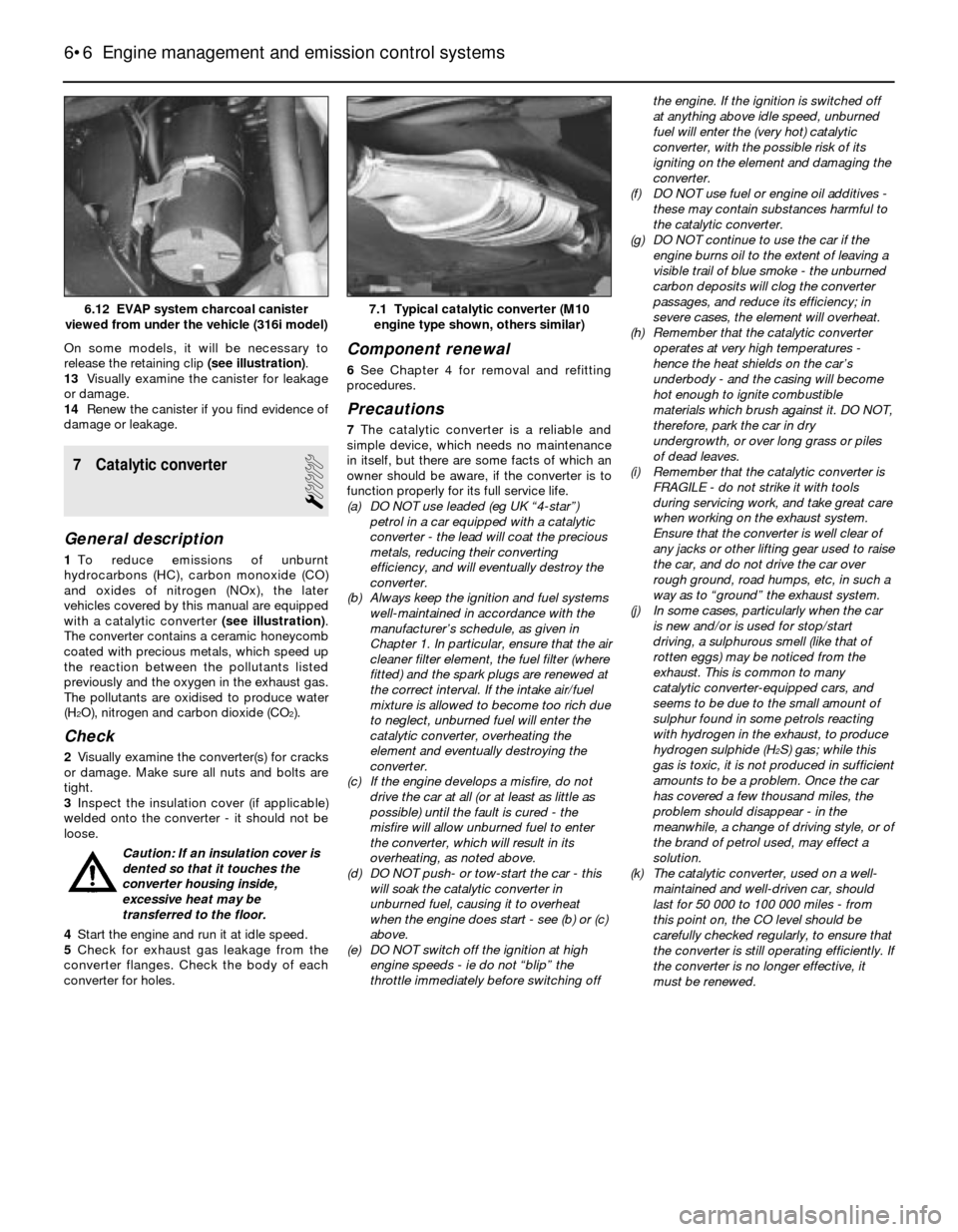
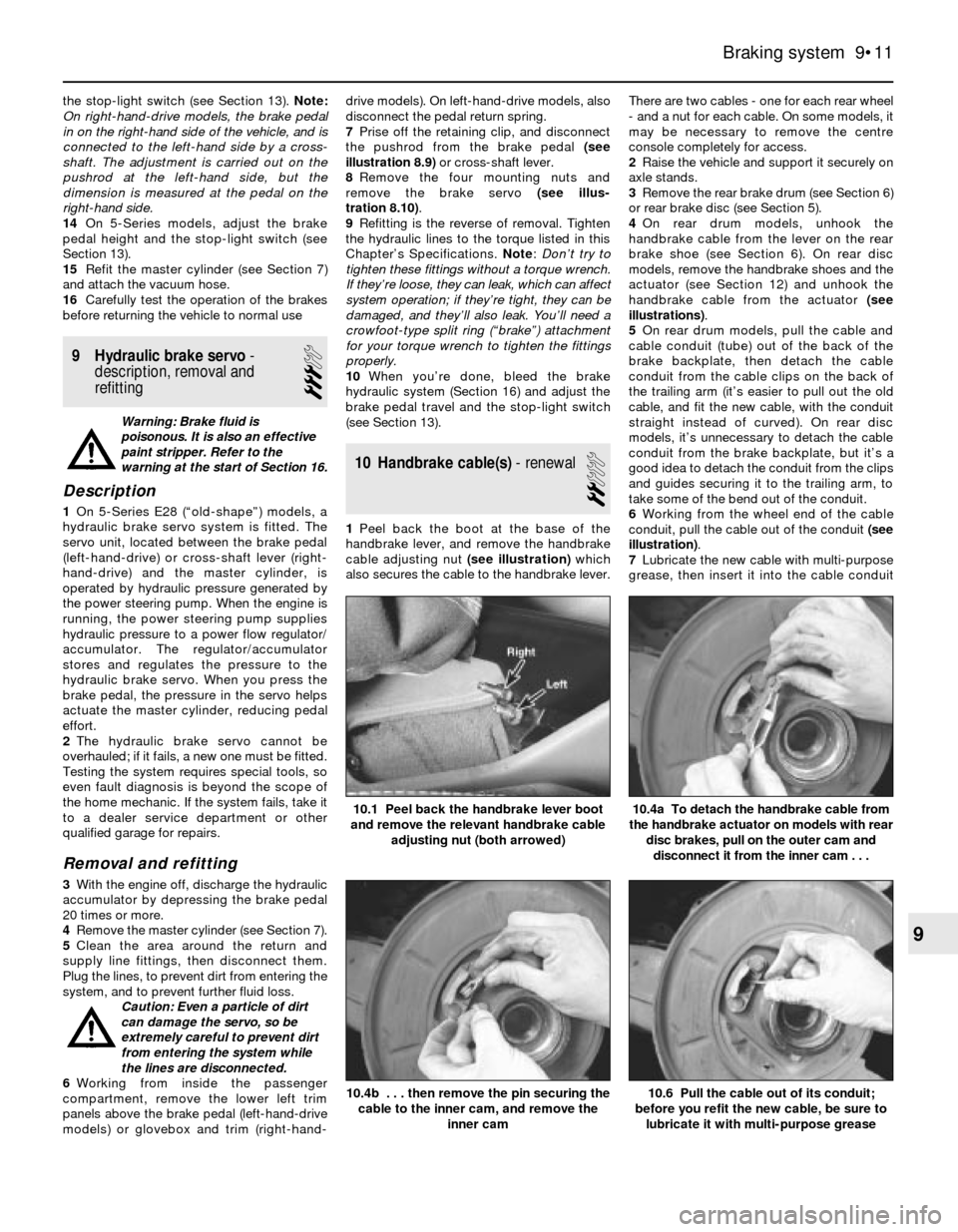
[x] Cancel search | Manufacturer: BMW, Model Year: 1991, Model line: 3 SERIES, Model: BMW 3 SERIES 1991 E30Pages: 228, PDF Size: 7.04 MB
Page 126 of 228
slightly by hand. Release the throttle slowly
until it reaches 0.2 to 0.6 mm from the throttle
stop. There should be continuity.
29Check the resistance between terminals 3
and 18 as the throttle is opened. There should
be continuity when the throttle switch is within
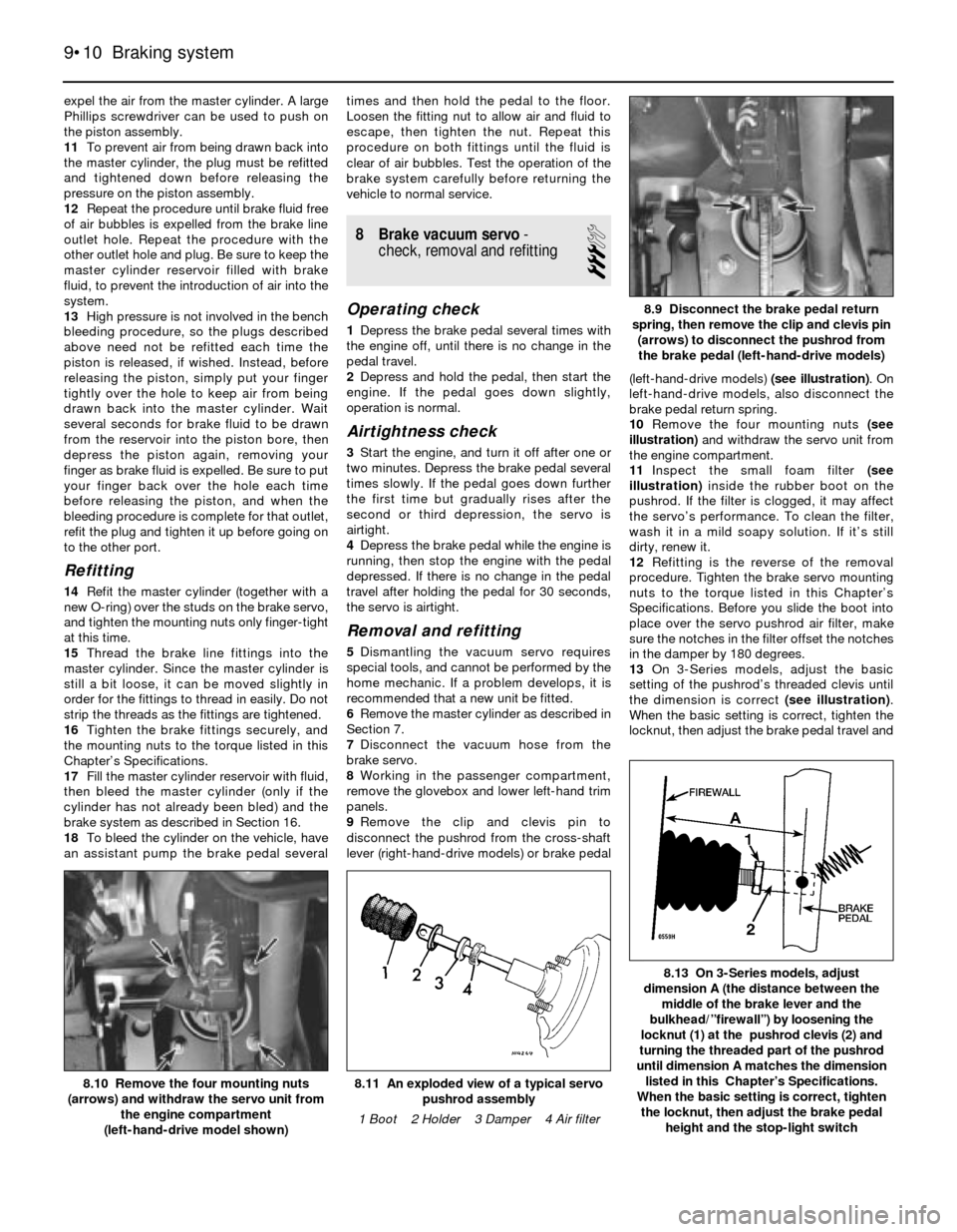
8 to 12 degrees of fully-open. If the readings
are incorrect, adjust the TPS.
30If all the resistance readings are correct
and the TPS is properly adjusted, check for
power (5 volts) at the sensor, and if necessary
trace any wiring circuit problems between the
sensor and ECU (see Chapter 12).
Adjustment
31If the adjustment is not as specified
(paragraphs 28 to 30), loosen the screws on
the TPS, and rotate the sensor into the correct
adjustment. Follow the procedure for
checking the TPS given above, and tighten
the screws when the setting is correct.
32Recheck the TPS once more; if the
readings are correct, reconnect the TPS
harness connector.
Early 535i models with automatic
transmission
Check
33First test the continuity of the TPS. Follow
paragraphs 28 to 30 and check for continuity.
34Next, test the idle position switch (see
illustration). Unplug the electrical connector
in the idle position switch harness, andconnect an ohmmeter to terminals 1 and 2.
There should be continuity. Open the throttle
slightly, and measure the resistance. There
should now be no continuity.
35Check for the correct voltage signals from
the TPS, with the throttle closed and the
ignition on. Probe the back of the TPS
connector with a voltmeter, and check for
voltage at terminal 3 (black wire) and earth.
There should be 5 volts present. Also, probe
terminal 3 (black wire) and terminal 1 (brown
wire). There should be 5 volts present here
also.
36Check for voltage at terminal 2 (yellow
wire) and terminal 1 (brown wire), and slowly
open the throttle. The voltage should increase
steadily from 0.7 volts (throttle closed) to
4.8 volts (throttle fully-open).
Adjustment
37First measure the stabilised voltage. With
the ignition on and the throttle closed,
measure the voltage between terminal 3
(black wire) and terminal 1 (brown wire). It
should be about 5 volts.
38Next, loosen the sensor mounting screws,
and connect the voltmeter to terminal 2
(yellow wire) and terminal 3 (black wire). With
the throttle fully open, rotate the switch until
there is 0.20 to 0.24 volts less than the
stabilised voltage. Note: You will need a
digital voltmeter to measure these small
changes in voltage.
39Recheck the TPS once more; if the
readings are correct, reconnect the TPS
electrical connector. It is a good idea to lock
the TPS screws with paint or thread-locking
compound.
Airflow meter
General description
40The airflow meter is located on the air
intake duct. The airflow meter measures the
amount of air entering the engine. The ECU
uses this information to control fuel delivery. A
large volume of air indicates acceleration,
while a small volume of air indicates
deceleration or idle. Refer to Chapter 4 for all
the diagnostic checks and renewal
procedures for the airflow meter.
Ignition timing sensors
41Ignition timing is electronically-controlled
on Motronic systems, and is not adjustable.
During starting, a crankshaft position sensor
relays the crankshaft position to the ECU, and
an initial baseline ignition point is determined.
Once the engine is running, the ignition point
is continually changing based on the various
input signals to the ECU. Engine speed is
signalled by a speed sensor. Early Motronic
systems have the reference sensor and the
speed sensor mounted on the bellhousing
over the flywheel. Later Motronic systems
have a single sensor (pulse sensor) mounted
over the crankshaft pulley. This sensor
functions as a speed sensor as well as a
position sensor. Refer to Chapter 5 for more
information. Note: Some models are
equipped with a TDC sensor mounted on the
front of the engine. This sensor is strictly for
the BMW service test unit, and it is not part of
the Motronic ignition system.
5 Positive crankcase
ventilation (PCV) system
1The Positive Crankcase Ventilation (PCV)
system (see illustration)reduces
hydrocarbon emissions by scavenging
crankcase vapours. It does this by circulating
blow-by gases and then re-routing them to
the intake manifold by way of the air cleaner.
2This PCV system is a sealed system. The
crankcase blow-by vapours are routed
directly to the air cleaner or air collector with
crankcase pressure behind them. The vapour
is not purged with fresh air on most models or
6•4 Engine management and emission control systems
5.2 PCV hose being removed from the
valve cover5.1 Diagram of the PCV system on the
M20 engine (others similar)4.34 Idle position switch and TPS on early
535i models with automatic transmission
4.28c . . . then check for continuity
between terminals 3 and 18 as the throttle
is opened
Page 128 of 228
On some models, it will be necessary to
release the retaining clip (see illustration).
13Visually examine the canister for leakage
or damage.
14Renew the canister if you find evidence of
damage or leakage.
7 Catalytic converter
1
General description
1To reduce emissions of unburnt
hydrocarbons (HC), carbon monoxide (CO)
and oxides of nitrogen (NOx), the later
vehicles covered by this manual are equipped
with a catalytic converter (see illustration).
The converter contains a ceramic honeycomb
coated with precious metals, which speed up
the reaction between the pollutants listed
previously and the oxygen in the exhaust gas.
The pollutants are oxidised to produce water
(H
2O), nitrogen and carbon dioxide (CO2).
Check
2Visually examine the converter(s) for cracks
or damage. Make sure all nuts and bolts are
tight.
3Inspect the insulation cover (if applicable)
welded onto the converter - it should not be
loose.
Caution: If an insulation cover is
dented so that it touches the
converter housing inside,
excessive heat may be
transferred to the floor.
4Start the engine and run it at idle speed.
5Check for exhaust gas leakage from the
converter flanges. Check the body of each
converter for holes.
Component renewal
6See Chapter 4 for removal and refitting
procedures.
Precautions
7The catalytic converter is a reliable and
simple device, which needs no maintenance
in itself, but there are some facts of which an
owner should be aware, if the converter is to
function properly for its full service life.
(a) DO NOT use leaded (eg UK “4-star”)
petrol in a car equipped with a catalytic
converter - the lead will coat the precious
metals, reducing their converting
efficiency, and will eventually destroy the
converter.
(b) Always keep the ignition and fuel systems
well-maintained in accordance with the
manufacturer’s schedule, as given in
Chapter 1. In particular, ensure that the air
cleaner filter element, the fuel filter (where
fitted) and the spark plugs are renewed at
the correct interval. If the intake air/fuel
mixture is allowed to become too rich due
to neglect, unburned fuel will enter the
catalytic converter, overheating the
element and eventually destroying the
converter.
(c) If the engine develops a misfire, do not
drive the car at all (or at least as little as
possible) until the fault is cured - the
misfire will allow unburned fuel to enter
the converter, which will result in its
overheating, as noted above.
(d) DO NOT push- or tow-start the car - this
will soak the catalytic converter in
unburned fuel, causing it to overheat
when the engine does start - see (b) or (c)
above.
(e) DO NOT switch off the ignition at high
engine speeds - ie do not “blip” the
throttle immediately before switching offthe engine. If the ignition is switched off
at anything above idle speed, unburned
fuel will enter the (very hot) catalytic
converter, with the possible risk of its
igniting on the element and damaging the
converter.
(f) DO NOT use fuel or engine oil additives -
these may contain substances harmful to
the catalytic converter.
(g) DO NOT continue to use the car if the
engine burns oil to the extent of leaving a
visible trail of blue smoke - the unburned
carbon deposits will clog the converter
passages, and reduce its efficiency; in
severe cases, the element will overheat.
(h) Remember that the catalytic converter
operates at very high temperatures -
hence the heat shields on the car’s
underbody - and the casing will become
hot enough to ignite combustible
materials which brush against it. DO NOT,
therefore, park the car in dry
undergrowth, or over long grass or piles
of dead leaves.
(i) Remember that the catalytic converter is
FRAGILE - do not strike it with tools
during servicing work, and take great care
when working on the exhaust system.
Ensure that the converter is well clear of
any jacks or other lifting gear used to raise
the car, and do not drive the car over
rough ground, road humps, etc, in such a
way as to “ground” the exhaust system.
(j) In some cases, particularly when the car
is new and/or is used for stop/start
driving, a sulphurous smell (like that of
rotten eggs) may be noticed from the
exhaust. This is common to many
catalytic converter-equipped cars, and
seems to be due to the small amount of
sulphur found in some petrols reacting
with hydrogen in the exhaust, to produce
hydrogen sulphide (H
2S) gas; while this
gas is toxic, it is not produced in sufficient
amounts to be a problem. Once the car
has covered a few thousand miles, the
problem should disappear - in the
meanwhile, a change of driving style, or of
the brand of petrol used, may effect a
solution.
(k) The catalytic converter, used on a well-
maintained and well-driven car, should
last for 50 000 to 100 000 miles - from
this point on, the CO level should be
carefully checked regularly, to ensure that
the converter is still operating efficiently. If
the converter is no longer effective, it
must be renewed.
6•6 Engine management and emission control systems
7.1 Typical catalytic converter (M10
engine type shown, others similar)6.12 EVAP system charcoal canister
viewed from under the vehicle (316i model)
Page 129 of 228

9
General
Brake fluid type . . . . . . . . . . . . . . . . . . . . . . . . . . . . . . . . . . . . . . . . . . . . See Chapter 1
Disc brakes
Minimum brake pad thickness . . . . . . . . . . . . . . . . . . . . . . . . . . . . . . . . See Chapter 1
Brake disc minimum permissible thickness (wear limit)*
Front
3-Series
Solid discs . . . . . . . . . . . . . . . . . . . . . . . . . . . . . . . . . . . . . . . . . . 10.7 mm
Ventilated discs . . . . . . . . . . . . . . . . . . . . . . . . . . . . . . . . . . . . . . 20.0 mm
5-Series
Solid discs . . . . . . . . . . . . . . . . . . . . . . . . . . . . . . . . . . . . . . . . . . 10.0 mm
Ventilated discs . . . . . . . . . . . . . . . . . . . . . . . . . . . . . . . . . . . . . . 20.0 mm
Rear . . . . . . . . . . . . . . . . . . . . . . . . . . . . . . . . . . . . . . . . . . . . . . . . . . 8.0 mm
Brake disc minimum thickness after machining
Front
3-Series
Solid discs . . . . . . . . . . . . . . . . . . . . . . . . . . . . . . . . . . . . . . . . . . 11.1 mm
Ventilated discs . . . . . . . . . . . . . . . . . . . . . . . . . . . . . . . . . . . . . . 20.4 mm
5-Series
Solid discs . . . . . . . . . . . . . . . . . . . . . . . . . . . . . . . . . . . . . . . . . . 10.4 mm
Ventilated discs . . . . . . . . . . . . . . . . . . . . . . . . . . . . . . . . . . . . . . 20.4 mm
Rear . . . . . . . . . . . . . . . . . . . . . . . . . . . . . . . . . . . . . . . . . . . . . . . . . . 8.4 mm
Parallelism (difference between any two measurements) . . . . . . . . . . . 0.02 mm
Maximum disc run-out . . . . . . . . . . . . . . . . . . . . . . . . . . . . . . . . . . . . . . 0.2 mm
*Refer to marks cast into the disc (they supersede information printed here)
Brake pedal adjustments
Brake pedal/servo pushrod adjustment (A) (3-Series) . . . . . . . . . . . . . . 125 mm
Brake pedal height (pedal-to-bulkhead distance)
3-Series
Left-hand-drive . . . . . . . . . . . . . . . . . . . . . . . . . . . . . . . . . . . . . . . . 235 mm
Right-hand-drive . . . . . . . . . . . . . . . . . . . . . . . . . . . . . . . . . . . . . . . 273 mm
5-Series . . . . . . . . . . . . . . . . . . . . . . . . . . . . . . . . . . . . . . . . . . . . . . . . 245 mm
Stop-light switch adjustment (dimension A - see text) . . . . . . . . . . . . . . 5.0 mm to 6.0 mm
Handbrake
Handbrake shoe lining minimum thickness . . . . . . . . . . . . . . . . . . . . . . 1.5 mm
Handbrake lever travel . . . . . . . . . . . . . . . . . . . . . . . . . . . . . . . . . . . . . . 5 to 8 clicks
Chapter 9 Braking system
Anti-lock brake system (ABS) - general information . . . . . . . . . . . . . 2
Brake check . . . . . . . . . . . . . . . . . . . . . . . . . . . . . . . . See Chapter 1
Brake disc - inspection, removal and refitting . . . . . . . . . . . . . . . . . 5
Brake fluid level check . . . . . . . . . . . . . . . . . . . . . . . . See Chapter 1
Brake hoses and lines - inspection and renewal . . . . . . . . . . . . . . . . 15
Brake hydraulic system - bleeding . . . . . . . . . . . . . . . . . . . . . . . . . . 16
Brake pedal - adjustment . . . . . . . . . . . . . . . . . . . . . . . . . . . . . . . . . 13
Brake vacuum servo - check, removal and refitting . . . . . . . . . . . . . 8
Disc brake caliper - removal, overhaul and refitting . . . . . . . . . . . . . 4Disc brake pads - renewal . . . . . . . . . . . . . . . . . . . . . . . . . . . . . . . . 3
Drum brake shoes - renewal . . . . . . . . . . . . . . . . . . . . . . . . . . . . . . . 6
General information . . . . . . . . . . . . . . . . . . . . . . . . . . . . . . . . . . . . . . 1
Handbrake assembly - check, removal and refitting . . . . . . . . . . . . 12
Handbrake - adjustment . . . . . . . . . . . . . . . . . . . . . . . . . . . . . . . . . . 11
Handbrake cable(s) - renewal . . . . . . . . . . . . . . . . . . . . . . . . . . . . . . 10
Hydraulic brake servo - description, removal and refitting . . . . . . . . 9
Master cylinder - removal and refitting . . . . . . . . . . . . . . . . . . . . . . . 7
Stop-light switch - check and adjustment . . . . . . . . . . . . . . . . . . . . 14
9•1
Easy,suitable for
novice with little
experienceFairly easy,suitable
for beginner with
some experienceFairly difficult,
suitable for competent
DIY mechanic
Difficult,suitable for
experienced DIY
mechanicVery difficult,
suitable for expert
DIY or professional
Degrees of difficulty
Specifications Contents
Page 130 of 228

Torque wrench settingsNm
Front disc brake caliper
Caliper guide (mounting) bolts . . . . . . . . . . . . . . . . . . . . . . . . . . . . . . 30 to 35
Caliper bracket-to-strut housing bolts
3-Series, E30 . . . . . . . . . . . . . . . . . . . . . . . . . . . . . . . . . . . . . . . . . . 123
5-Series, E28 (“old-shape”) . . . . . . . . . . . . . . . . . . . . . . . . . . . . . . . 123
5-Series, E34 (“new-shape”) . . . . . . . . . . . . . . . . . . . . . . . . . . . . . . 110
Rear disc brake caliper
Caliper guide (mounting) bolts . . . . . . . . . . . . . . . . . . . . . . . . . . . . . . 30 to 35
Carrier-to-trailing arm bolts . . . . . . . . . . . . . . . . . . . . . . . . . . . . . . . . 67
Brake hose-to-caliper fitting . . . . . . . . . . . . . . . . . . . . . . . . . . . . . . . . . . 14 to 17
Master cylinder-to-brake servo nuts
3-Series . . . . . . . . . . . . . . . . . . . . . . . . . . . . . . . . . . . . . . . . . . . . . . . . 24
5-Series . . . . . . . . . . . . . . . . . . . . . . . . . . . . . . . . . . . . . . . . . . . . . . . . 25 to 29
Brake servo mounting nuts . . . . . . . . . . . . . . . . . . . . . . . . . . . . . . . . . . . 22 to 24
Hydraulic line-to-hydraulic brake servo threaded
fittings - 5-Series, E28 (“old-shape”) . . . . . . . . . . . . . . . . . . . . . . . . . . . 31
Wheel bolts . . . . . . . . . . . . . . . . . . . . . . . . . . . . . . . . . . . . . . . . . . . . . . . See Chapter 1
9•2 Braking system
1 General information
All 3-Series models, and 5-Series E28 (“old-
shape”) models, are equipped with front disc
brakes and either rear drum or rear disc
brakes. 5-Series E34 (“new-shape”) models
have disc brakes front and rear. Front and
rear brakes are self-adjusting on all models.
Some later models are equipped with an Anti-
lock Braking System (ABS); this is described
in Section 2.
Hydraulic system
The hydraulic system consists of two
separate circuits. The master cylinder has
separate reservoirs for the two circuits; in the
event of a leak or failure in one hydraulic
circuit, the other circuit will remain operative.
Brake servo
The vacuum brake servo, utilising engine
manifold vacuum and atmospheric pressure
to provide assistance to the hydraulically
operated brakes, is mounted on the bulkhead
in the engine compartment.
A hydraulic brake servo system is used on
5-Series E28 models. This system uses
hydraulic pressure from the power steering
pump to assist braking.
Handbrake
The handbrake operates the rear brakes,
and is cable-operated via a lever mounted in
the centre console. The handbrake assembly
on rear drum brake models is part of the rear
drum brake assembly, and is self-adjusting.
On rear disc brake models, the handbrake
uses a pair of brake shoes located inside the
centre portion of the rear brake disc, and is
manually-adjusted.
Brake pad wear warning system
The brake pad wear warning system is
linked to a red warning light in the instrumentcluster, which comes on when the brake pads
have worn down to the point at which they
require renewal. DO NOT ignore this reminder.
If you don’t renew the pads shortly after the
brake pad wear warning light comes on, the
brake discs will be damaged.
On some models, the brake pad wear
warning system also includes an early
warning light that comes on only when the
brake pedal is depressed, letting you know in
advance that the pads need to be renewed.
The wear sensor is attached to the brake
pads. The sensor is located at the left front
wheel; on some models, there is another
sensor at the right rear wheel. The wear
sensor is part of a closed circuit. Once the
pads wear down to the point at which they’re
flush with the sensor, the disc grinds away the
side of the sensor facing the disc. Thus, the
wire inside the sensor is broken, and the red
light on the instrument panel comes on.
Always check the sensor(s) when renewing
the pads. If you change the pads before the
warning light comes on, the sensor(s) may still
be good; once the light has come on, renew
the sensor.
Service
After completing any operation involving
dismantling of any part of the brake system,
always test drive the vehicle to check for
proper braking performance before resuming
normal driving. When testing the brakes, try to
select a clean, dry, road with no camber (ie as
flat as possible) and with no other traffic.
Conditions other than these can lead to
inaccurate test results.
Test the brakes at various speeds with both
light and heavy pedal pressure. The vehicle
should stop evenly, without pulling to one side
or the other. Avoid locking the brakes,
because this slides the tyres and diminishes
braking efficiency and control of the vehicle.
Tyres, vehicle load and wheel alignment are
factors which also affect braking
performance.
2 Anti-lock Braking system
(ABS)- general information
The Anti-lock Braking System is designed
to maintain vehicle control, directional stability
and optimum deceleration under severe
braking conditions on most road surfaces. It
does so by monitoring the rotational speed of
each wheel and controlling the brake line
pressure to each wheel during braking. This
prevents the wheels from locking up.
The ABS system has three main
components - the wheel speed sensors, the
electronic control unit, and the hydraulic
control unit. The sensors - one at each wheel
since 1985, but at both front wheels and one
at the rear differential on earlier models - send
a variable voltage signal to the control unit,
which monitors these signals, compares them
to its program information, and determines
whether a wheel is about to lock up. When a
wheel is about to lock up, the control unit
signals the hydraulic unit to reduce hydraulic
pressure (or not increase it further) at that
wheel’s brake caliper. Pressure modulation is
handled by electrically-operated solenoid
valves.
If a problem develops within the system, an
“ABS” warning light will glow on the
dashboard. Sometimes, a visual inspection of
the ABS system can help you locate the
problem. Carefully inspect the ABS wiring
harness. Pay particularly close attention to the
harness and connections near each wheel.
Look for signs of chafing and other damage
caused by incorrectly-routed wires. If a wheel
sensor harness is damaged, the sensor
should be renewed (the harness and sensor
are integral).
Warning: DO NOT try to repair an
ABS wiring harness. The ABS
system is sensitive to even the
smallest changes in resistance. Repairing
the harness could alter resistance values
Page 138 of 228
expel the air from the master cylinder. A large
Phillips screwdriver can be used to push on
the piston assembly.
11To prevent air from being drawn back into
the master cylinder, the plug must be refitted
and tightened down before releasing the
pressure on the piston assembly.
12Repeat the procedure until brake fluid free
of air bubbles is expelled from the brake line
outlet hole. Repeat the procedure with the
other outlet hole and plug. Be sure to keep the
master cylinder reservoir filled with brake
fluid, to prevent the introduction of air into the
system.
13High pressure is not involved in the bench
bleeding procedure, so the plugs described
above need not be refitted each time the
piston is released, if wished. Instead, before
releasing the piston, simply put your finger
tightly over the hole to keep air from being
drawn back into the master cylinder. Wait
several seconds for brake fluid to be drawn
from the reservoir into the piston bore, then
depress the piston again, removing your
finger as brake fluid is expelled. Be sure to put
your finger back over the hole each time
before releasing the piston, and when the
bleeding procedure is complete for that outlet,
refit the plug and tighten it up before going on
to the other port.
Refitting
14Refit the master cylinder (together with a
new O-ring) over the studs on the brake servo,
and tighten the mounting nuts only finger-tight
at this time.
15Thread the brake line fittings into the
master cylinder. Since the master cylinder is
still a bit loose, it can be moved slightly in
order for the fittings to thread in easily. Do not
strip the threads as the fittings are tightened.
16Tighten the brake fittings securely, and
the mounting nuts to the torque listed in this
Chapter’s Specifications.
17Fill the master cylinder reservoir with fluid,
then bleed the master cylinder (only if the
cylinder has not already been bled) and the
brake system as described in Section 16.
18To bleed the cylinder on the vehicle, have
an assistant pump the brake pedal severaltimes and then hold the pedal to the floor.
Loosen the fitting nut to allow air and fluid to
escape, then tighten the nut. Repeat this
procedure on both fittings until the fluid is
clear of air bubbles. Test the operation of the
brake system carefully before returning the
vehicle to normal service.
8 Brake vacuum servo-
check, removal and refitting
3
Operating check
1Depress the brake pedal several times with
the engine off, until there is no change in the
pedal travel.
2Depress and hold the pedal, then start the
engine. If the pedal goes down slightly,
operation is normal.
Airtightness check
3Start the engine, and turn it off after one or
two minutes. Depress the brake pedal several
times slowly. If the pedal goes down further
the first time but gradually rises after the
second or third depression, the servo is
airtight.
4Depress the brake pedal while the engine is
running, then stop the engine with the pedal
depressed. If there is no change in the pedal
travel after holding the pedal for 30 seconds,
the servo is airtight.
Removal and refitting
5Dismantling the vacuum servo requires
special tools, and cannot be performed by the
home mechanic. If a problem develops, it is
recommended that a new unit be fitted.
6Remove the master cylinder as described in
Section 7.
7Disconnect the vacuum hose from the
brake servo.
8Working in the passenger compartment,
remove the glovebox and lower left-hand trim
panels.
9Remove the clip and clevis pin to
disconnect the pushrod from the cross-shaft
lever (right-hand-drive models) or brake pedal(left-hand-drive models) (see illustration). On
left-hand-drive models, also disconnect the
brake pedal return spring.
10Remove the four mounting nuts (see
illustration)and withdraw the servo unit from
the engine compartment.
11Inspect the small foam filter (see
illustration)inside the rubber boot on the
pushrod. If the filter is clogged, it may affect
the servo’s performance. To clean the filter,
wash it in a mild soapy solution. If it’s still
dirty, renew it.
12Refitting is the reverse of the removal
procedure. Tighten the brake servo mounting
nuts to the torque listed in this Chapter’s
Specifications. Before you slide the boot into
place over the servo pushrod air filter, make
sure the notches in the filter offset the notches
in the damper by 180 degrees.
13On 3-Series models, adjust the basic
setting of the pushrod’s threaded clevis until
the dimension is correct (see illustration).
When the basic setting is correct, tighten the
locknut, then adjust the brake pedal travel and
9•10 Braking system
8.13 On 3-Series models, adjust
dimension A (the distance between the
middle of the brake lever and the
bulkhead/”firewall”) by loosening the
locknut (1) at the pushrod clevis (2) and
turning the threaded part of the pushrod
until dimension A matches the dimension
listed in this Chapter’s Specifications.
When the basic setting is correct, tighten
the locknut, then adjust the brake pedal
height and the stop-light switch
8.11 An exploded view of a typical servo
pushrod assembly
1 Boot 2 Holder 3 Damper 4 Air filter8.10 Remove the four mounting nuts
(arrows) and withdraw the servo unit from
the engine compartment
(left-hand-drive model shown)
8.9 Disconnect the brake pedal return
spring, then remove the clip and clevis pin
(arrows) to disconnect the pushrod from
the brake pedal (left-hand-drive models)
Page 139 of 228
the stop-light switch (see Section 13). Note:
On right-hand-drive models, the brake pedal
in on the right-hand side of the vehicle, and is
connected to the left-hand side by a cross-
shaft. The adjustment is carried out on the
pushrod at the left-hand side, but the
dimension is measured at the pedal on the
right-hand side.
14On 5-Series models, adjust the brake
pedal height and the stop-light switch (see
Section 13).
15Refit the master cylinder (see Section 7)
and attach the vacuum hose.
16Carefully test the operation of the brakes
before returning the vehicle to normal use
9 Hydraulic brake servo-
description, removal and
refitting
3
Warning: Brake fluid is
poisonous. It is also an effective
paint stripper. Refer to the
warning at the start of Section 16.
Description
1On 5-Series E28 (“old-shape”) models, a
hydraulic brake servo system is fitted. The
servo unit, located between the brake pedal
(left-hand-drive) or cross-shaft lever (right-
hand-drive) and the master cylinder, is
operated by hydraulic pressure generated by
the power steering pump. When the engine is
running, the power steering pump supplies
hydraulic pressure to a power flow regulator/
accumulator. The regulator/accumulator
stores and regulates the pressure to the
hydraulic brake servo. When you press the
brake pedal, the pressure in the servo helps
actuate the master cylinder, reducing pedal
effort.
2The hydraulic brake servo cannot be
overhauled; if it fails, a new one must be fitted.
Testing the system requires special tools, so
even fault diagnosis is beyond the scope of
the home mechanic. If the system fails, take it
to a dealer service department or other
qualified garage for repairs.
Removal and refitting
3With the engine off, discharge the hydraulic
accumulator by depressing the brake pedal
20 times or more.
4Remove the master cylinder (see Section 7).
5Clean the area around the return and
supply line fittings, then disconnect them.
Plug the lines, to prevent dirt from entering the
system, and to prevent further fluid loss.
Caution: Even a particle of dirt
can damage the servo, so be
extremely careful to prevent dirt
from entering the system while
the lines are disconnected.
6Working from inside the passenger
compartment, remove the lower left trim
panels above the brake pedal (left-hand-drive
models) or glovebox and trim (right-hand-drive models). On left-hand-drive models, also
disconnect the pedal return spring.
7Prise off the retaining clip, and disconnect
the pushrod from the brake pedal (see
illustration 8.9) or cross-shaft lever.
8Remove the four mounting nuts and
remove the brake servo (see illus-
tration 8.10).
9Refitting is the reverse of removal. Tighten
the hydraulic lines to the torque listed in this
Chapter’s Specifications. Note:Don’t try to
tighten these fittings without a torque wrench.
If they’re loose, they can leak, which can affect
system operation; if they’re tight, they can be
damaged, and they’ll also leak. You’ll need a
crowfoot-type split ring (“brake”) attachment
for your torque wrench to tighten the fittings
properly.
10When you’re done, bleed the brake
hydraulic system (Section 16) and adjust the
brake pedal travel and the stop-light switch
(see Section 13).
10 Handbrake cable(s)- renewal
2
1Peel back the boot at the base of the
handbrake lever, and remove the handbrake
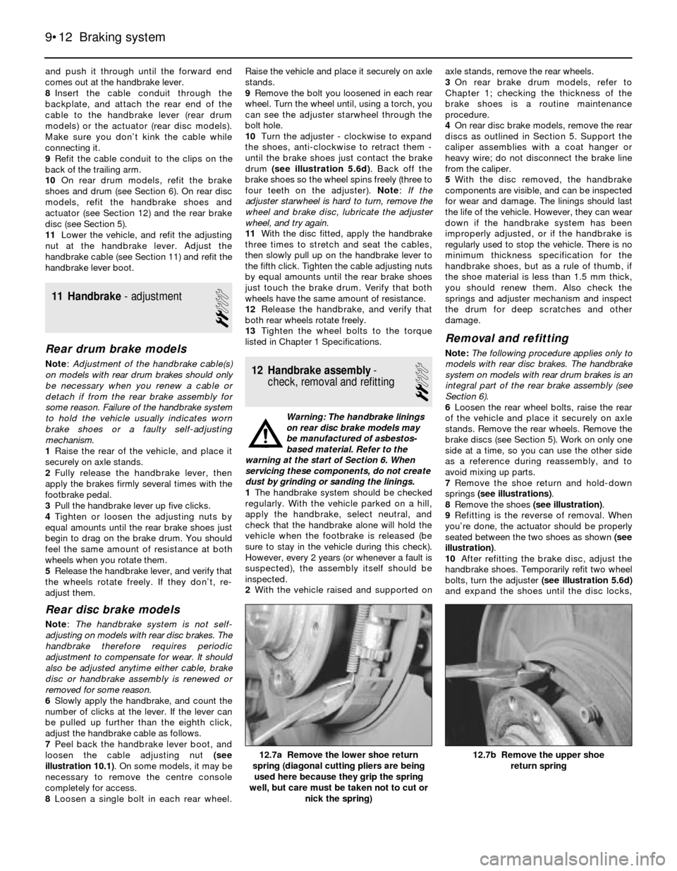
cable adjusting nut (see illustration)which
also secures the cable to the handbrake lever.There are two cables - one for each rear wheel
- and a nut for each cable. On some models, it
may be necessary to remove the centre
console completely for access.
2Raise the vehicle and support it securely on
axle stands.
3Remove the rear brake drum (see Section 6)
or rear brake disc (see Section 5).
4On rear drum models, unhook the
handbrake cable from the lever on the rear
brake shoe (see Section 6). On rear disc
models, remove the handbrake shoes and the
actuator (see Section 12) and unhook the
handbrake cable from the actuator (see
illustrations).
5On rear drum models, pull the cable and
cable conduit (tube) out of the back of the
brake backplate, then detach the cable
conduit from the cable clips on the back of
the trailing arm (it’s easier to pull out the old
cable, and fit the new cable, with the conduit
straight instead of curved). On rear disc
models, it’s unnecessary to detach the cable
conduit from the brake backplate, but it’s a
good idea to detach the conduit from the clips
and guides securing it to the trailing arm, to
take some of the bend out of the conduit.
6Working from the wheel end of the cable
conduit, pull the cable out of the conduit (see
illustration).
7Lubricate the new cable with multi-purpose
grease, then insert it into the cable conduit
Braking system 9•11
10.1 Peel back the handbrake lever boot
and remove the relevant handbrake cable
adjusting nut (both arrowed)
10.6 Pull the cable out of its conduit;
before you refit the new cable, be sure to
lubricate it with multi-purpose grease10.4b . . . then remove the pin securing the
cable to the inner cam, and remove the
inner cam
10.4a To detach the handbrake cable from
the handbrake actuator on models with rear
disc brakes, pull on the outer cam and
disconnect it from the inner cam . . .
9
Page 140 of 228
and push it through until the forward end
comes out at the handbrake lever.
8Insert the cable conduit through the
backplate, and attach the rear end of the
cable to the handbrake lever (rear drum
models) or the actuator (rear disc models).
Make sure you don’t kink the cable while
connecting it.
9Refit the cable conduit to the clips on the
back of the trailing arm.
10On rear drum models, refit the brake
shoes and drum (see Section 6). On rear disc
models, refit the handbrake shoes and
actuator (see Section 12) and the rear brake
disc (see Section 5).
11Lower the vehicle, and refit the adjusting
nut at the handbrake lever. Adjust the
handbrake cable (see Section 11) and refit the
handbrake lever boot.
11 Handbrake- adjustment
2
Rear drum brake models
Note:Adjustment of the handbrake cable(s)
on models with rear drum brakes should only
be necessary when you renew a cable or
detach if from the rear brake assembly for
some reason. Failure of the handbrake system
to hold the vehicle usually indicates worn
brake shoes or a faulty self-adjusting
mechanism.
1Raise the rear of the vehicle, and place it
securely on axle stands.
2Fully release the handbrake lever, then
apply the brakes firmly several times with the
footbrake pedal.
3Pull the handbrake lever up five clicks.
4Tighten or loosen the adjusting nuts by
equal amounts until the rear brake shoes just
begin to drag on the brake drum. You should
feel the same amount of resistance at both
wheels when you rotate them.
5Release the handbrake lever, and verify that
the wheels rotate freely. If they don’t, re-
adjust them.
Rear disc brake models
Note: The handbrake system is not self-
adjusting on models with rear disc brakes. The
handbrake therefore requires periodic
adjustment to compensate for wear. It should
also be adjusted anytime either cable, brake
disc or handbrake assembly is renewed or
removed for some reason.
6Slowly apply the handbrake, and count the
number of clicks at the lever. If the lever can
be pulled up further than the eighth click,
adjust the handbrake cable as follows.
7Peel back the handbrake lever boot, and
loosen the cable adjusting nut (see
illustration 10.1). On some models, it may be
necessary to remove the centre console
completely for access.
8Loosen a single bolt in each rear wheel.Raise the vehicle and place it securely on axle
stands.
9Remove the bolt you loosened in each rear
wheel. Turn the wheel until, using a torch, you
can see the adjuster starwheel through the
bolt hole.
10Turn the adjuster - clockwise to expand
the shoes, anti-clockwise to retract them -
until the brake shoes just contact the brake
drum (see illustration 5.6d). Back off the
brake shoes so the wheel spins freely (three to
four teeth on the adjuster). Note:If the
adjuster starwheel is hard to turn, remove the
wheel and brake disc, lubricate the adjuster
wheel, and try again.
11With the disc fitted, apply the handbrake
three times to stretch and seat the cables,
then slowly pull up on the handbrake lever to
the fifth click. Tighten the cable adjusting nuts
by equal amounts until the rear brake shoes
just touch the brake drum. Verify that both
wheels have the same amount of resistance.
12Release the handbrake, and verify that
both rear wheels rotate freely.
13Tighten the wheel bolts to the torque
listed in Chapter 1 Specifications.
12 Handbrake assembly-
check, removal and refitting
2
Warning: The handbrake linings
on rear disc brake models may
be manufactured of asbestos-
based material. Refer to the
warning at the start of Section 6. When
servicing these components, do not create
dust by grinding or sanding the linings.
1The handbrake system should be checked
regularly. With the vehicle parked on a hill,
apply the handbrake, select neutral, and
check that the handbrake alone will hold the
vehicle when the footbrake is released (be
sure to stay in the vehicle during this check).
However, every 2 years (or whenever a fault is
suspected), the assembly itself should be
inspected.
2With the vehicle raised and supported onaxle stands, remove the rear wheels.
3On rear brake drum models, refer to
Chapter 1; checking the thickness of the
brake shoes is a routine maintenance
procedure.
4On rear disc brake models, remove the rear
discs as outlined in Section 5. Support the
caliper assemblies with a coat hanger or
heavy wire; do not disconnect the brake line
from the caliper.
5With the disc removed, the handbrake
components are visible, and can be inspected
for wear and damage. The linings should last
the life of the vehicle. However, they can wear
down if the handbrake system has been
improperly adjusted, or if the handbrake is
regularly used to stop the vehicle. There is no
minimum thickness specification for the
handbrake shoes, but as a rule of thumb, if
the shoe material is less than 1.5 mm thick,
you should renew them. Also check the
springs and adjuster mechanism and inspect
the drum for deep scratches and other
damage.
Removal and refitting
Note:The following procedure applies only to
models with rear disc brakes. The handbrake
system on models with rear drum brakes is an
integral part of the rear brake assembly (see
Section 6).
6Loosen the rear wheel bolts, raise the rear
of the vehicle and place it securely on axle
stands. Remove the rear wheels. Remove the
brake discs (see Section 5). Work on only one
side at a time, so you can use the other side
as a reference during reassembly, and to
avoid mixing up parts.
7Remove the shoe return and hold-down
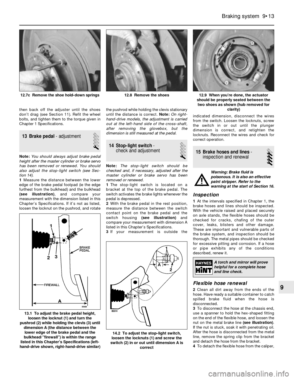
springs (see illustrations).
8Remove the shoes (see illustration).
9Refitting is the reverse of removal. When
you’re done, the actuator should be properly
seated between the two shoes as shown (see
illustration).
10After refitting the brake disc, adjust the
handbrake shoes. Temporarily refit two wheel
bolts, turn the adjuster (see illustration 5.6d)
and expand the shoes until the disc locks,
9•12 Braking system
12.7b Remove the upper shoe
return spring12.7a Remove the lower shoe return
spring (diagonal cutting pliers are being
used here because they grip the spring
well, but care must be taken not to cut or
nick the spring)
Page 141 of 228
then back off the adjuster until the shoes
don’t drag (see Section 11). Refit the wheel
bolts, and tighten them to the torque given in
Chapter 1 Specifications.
13 Brake pedal- adjustment
1
Note:You should always adjust brake pedal
height after the master cylinder or brake servo
has been removed or renewed. You should
also adjust the stop-light switch (see Sec-
tion 14).
1Measure the distance between the lower
edge of the brake pedal footpad (ie the edge
furthest from the bulkhead) and the bulkhead
(see illustration), and compare your
measurement with the dimension listed in this
Chapter’s Specifications. If it’s not as listed,
loosen the locknut on the pushrod, and rotatethe pushrod while holding the clevis stationary
until the distance is correct. Note:On right-
hand-drive models, the adjustment is carried
out at the left-hand side of the cross-shaft,
after removing the glovebox, but the
dimension is still measured at the pedal.
14 Stop-light switch-
check and adjustment
1
Note:The stop-light switch should be
checked and, if necessary, adjusted after the
master cylinder or brake servo has been
removed or renewed.
1The stop-light switch is located on a
bracket at the top of the brake pedal. The
switch activates the brake lights whenever the
pedal is depressed.
2With the brake pedal in the rest position,
measure the distance between the switch
contact point on the brake pedal and the
switch housing (see illustration)and
compare your measurement with dimension A
listed in this Chapter’s Specifications.
3If your measurement is outside theindicated dimension, disconnect the wires
from the switch. Loosen the locknuts, screw
the switch in or out until the plunger
dimension is correct, and retighten the
locknuts. Reconnect the wires and check for
correct operation.
15 Brake hoses and lines-
inspection and renewal
4
Warning: Brake fluid is
poisonous. It is also an effective
paint stripper. Refer to the
warning at the start of Section 16.
Inspection
1At the intervals specified in Chapter 1, the
brake hoses and lines should be inspected.
With the vehicle raised and placed securely
on axle stands, the flexible hoses should be
checked for cracks, chafing of the outer
cover, leaks, blisters and other damage.
These are important and vulnerable parts of
the brake system, and inspection should be
thorough. The metal pipes should be checked
for excessive pitting and corrosion. If a hose
or pipe exhibits any of the conditions
described, renew it.
Flexible hose renewal
2Clean all dirt away from the ends of the
hose. Have ready a suitable container to catch
spilled brake fluid when the hose is
disconnected.
3To disconnect the hose at the chassis end,
use a spanner to hold the hex-shaped fitting
on the end of the flexible hose, and loosen the
nut on the metal brake line (see illustration).
If the nut is stuck, soak it with penetrating oil.
After the hose is disconnected from the metal
line, remove the spring clip from the bracket
and detach the hose from the bracket.
4To detach the flexible hose from the caliper,
Braking system 9•13
12.9 When you’re done, the actuator
should be properly seated between the
two shoes as shown (hub removed for
clarity)12.8 Remove the shoes12.7c Remove the shoe hold-down springs
14.2 To adjust the stop-light switch,
loosen the locknuts (1) and screw the
switch (2) in or out until dimension A is
correct
13.1 To adjust the brake pedal height,
loosen the locknut (1) and turn the
pushrod (2) while holding the clevis (3) until
dimension A (the distance between the
lower edge of the brake pedal and the
bulkhead/”firewall”) is within the range
listed in this Chapter’s Specifications (left-
hand-drive shown, right-hand-drive similar)
9
A torch and mirror will prove
helpful for a complete hose
and line check.
Page 146 of 228
2 Front anti-roll bar-
removal and refitting
2
Removal
1Raise the front of the vehicle, and support it
securely on axle stands.
2If you’re removing or renewing the anti-roll
bar itself, or disconnecting the bar to renew
the strut assembly on a 3-Series model,
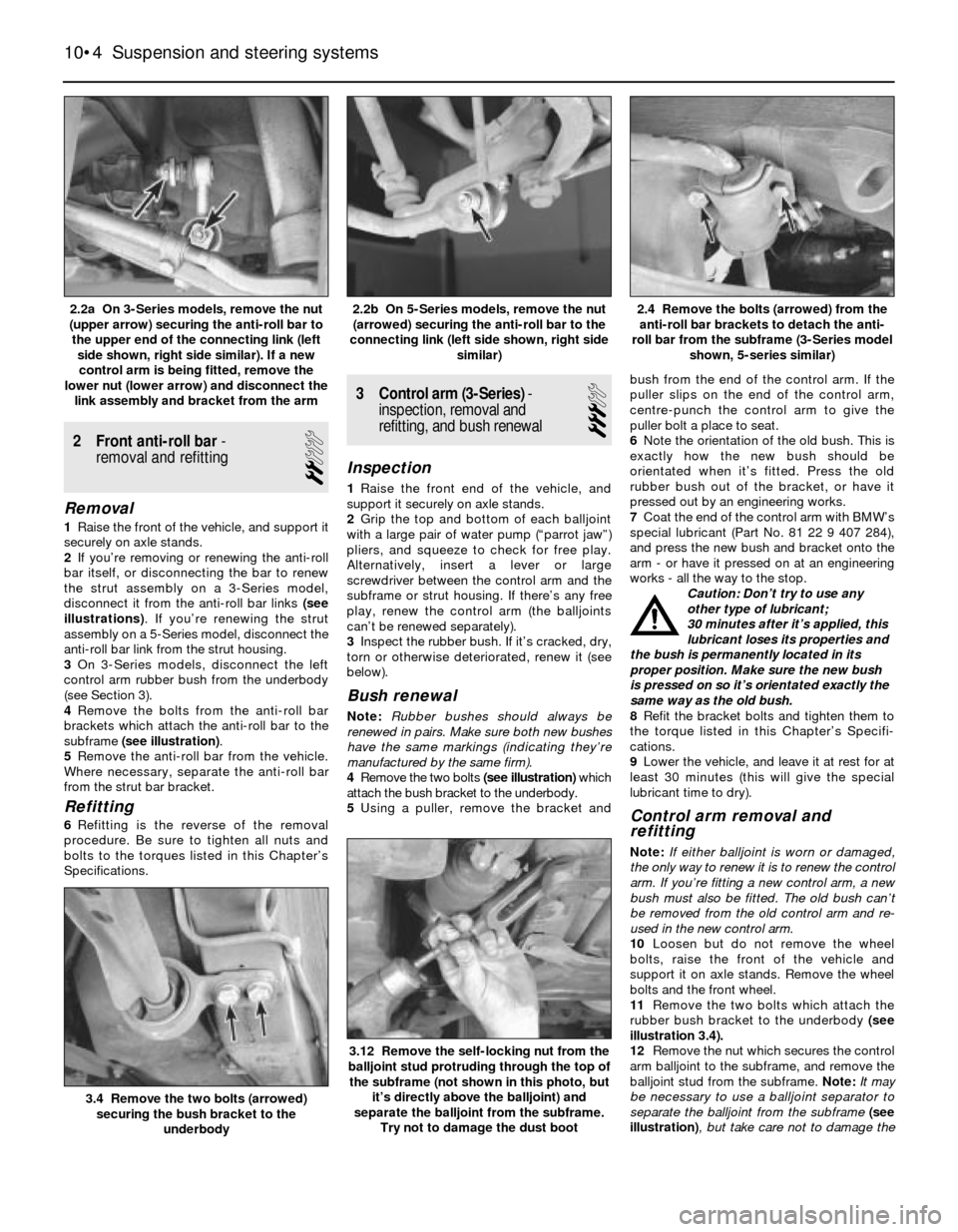
disconnect it from the anti-roll bar links (see
illustrations). If you’re renewing the strut
assembly on a 5-Series model, disconnect the
anti-roll bar link from the strut housing.
3On 3-Series models, disconnect the left
control arm rubber bush from the underbody
(see Section 3).
4Remove the bolts from the anti-roll bar
brackets which attach the anti-roll bar to the
subframe (see illustration).
5Remove the anti-roll bar from the vehicle.
Where necessary, separate the anti-roll bar
from the strut bar bracket.
Refitting
6Refitting is the reverse of the removal
procedure. Be sure to tighten all nuts and
bolts to the torques listed in this Chapter’s
Specifications.
3 Control arm (3-Series)-
inspection, removal and
refitting, and bush renewal
3
Inspection
1Raise the front end of the vehicle, and
support it securely on axle stands.
2Grip the top and bottom of each balljoint
with a large pair of water pump (“parrot jaw”)
pliers, and squeeze to check for free play.
Alternatively, insert a lever or large
screwdriver between the control arm and the
subframe or strut housing. If there’s any free
play, renew the control arm (the balljoints
can’t be renewed separately).
3Inspect the rubber bush. If it’s cracked, dry,
torn or otherwise deteriorated, renew it (see
below).
Bush renewal
Note:Rubber bushes should always be
renewed in pairs. Make sure both new bushes
have the same markings (indicating they’re
manufactured by the same firm).
4Remove the two bolts (see illustration)which
attach the bush bracket to the underbody.
5Using a puller, remove the bracket andbush from the end of the control arm. If the
puller slips on the end of the control arm,
centre-punch the control arm to give the
puller bolt a place to seat.
6Note the orientation of the old bush. This is
exactly how the new bush should be
orientated when it’s fitted. Press the old
rubber bush out of the bracket, or have it
pressed out by an engineering works.
7Coat the end of the control arm with BMW’s
special lubricant (Part No. 81 22 9 407 284),
and press the new bush and bracket onto the
arm - or have it pressed on at an engineering
works - all the way to the stop.
Caution: Don’t try to use any
other type of lubricant;
30 minutes after it’s applied, this
lubricant loses its properties and
the bush is permanently located in its
proper position. Make sure the new bush
is pressed on so it’s orientated exactly the
same way as the old bush.
8Refit the bracket bolts and tighten them to
the torque listed in this Chapter’s Specifi-
cations.
9Lower the vehicle, and leave it at rest for at
least 30 minutes (this will give the special
lubricant time to dry).
Control arm removal and
refitting
Note:If either balljoint is worn or damaged,
the only way to renew it is to renew the control
arm. If you’re fitting a new control arm, a new
bush must also be fitted. The old bush can’t
be removed from the old control arm and re-
used in the new control arm.
10Loosen but do not remove the wheel
bolts, raise the front of the vehicle and
support it on axle stands. Remove the wheel
bolts and the front wheel.
11Remove the two bolts which attach the
rubber bush bracket to the underbody (see
illustration 3.4).
12Remove the nut which secures the control
arm balljoint to the subframe, and remove the
balljoint stud from the subframe. Note:It may
be necessary to use a balljoint separator to
separate the balljoint from the subframe (see
illustration), but take care not to damage the
10•4 Suspension and steering systems
3.12 Remove the self-locking nut from the
balljoint stud protruding through the top of
the subframe (not shown in this photo, but
it’s directly above the balljoint) and
separate the balljoint from the subframe.
Try not to damage the dust boot
3.4 Remove the two bolts (arrowed)
securing the bush bracket to the
underbody
2.4 Remove the bolts (arrowed) from the
anti-roll bar brackets to detach the anti-
roll bar from the subframe (3-Series model
shown, 5-series similar)2.2b On 5-Series models, remove the nut
(arrowed) securing the anti-roll bar to the
connecting link (left side shown, right side
similar)2.2a On 3-Series models, remove the nut
(upper arrow) securing the anti-roll bar to
the upper end of the connecting link (left
side shown, right side similar). If a new
control arm is being fitted, remove the
lower nut (lower arrow) and disconnect the
link assembly and bracket from the arm
Page 161 of 228
3 Interior trim- maintenance
1
Interior trim panels can be kept clean by
wiping with a damp cloth. If they do become
stained (which can be more apparent on light-
coloured trim), use a little liquid detergent and
a soft nail brush to scour the grime out of the
grain of the material. Do not forget to keep the
headlining clean in the same way. After
cleaning, application of a high-quality rubber
and vinyl protector will help prevent oxidation
and cracks. The protector can also be applied
to weatherstrips, vacuum lines and rubber
hoses, which often fail as a result of chemical
degradation, and to the tyres.
4 Upholstery and carpets-
maintenance
1
Mats and carpets should be brushed or
vacuum-cleaned regularly, to keep them free
of grit. If they are badly stained, remove them
from the vehicle for scrubbing or sponging,
and make quite sure they are dry before
refitting. Seats and interior trim panels can be
kept clean by wiping with a damp cloth. If they
do become stained (which can be more
apparent on light-coloured upholstery), use a
little liquid detergent and a soft nail brush to
scour the grime out of the grain of the
material. Do not forget to keep the headlining
clean in the same way as the upholstery.
When using liquid cleaners inside the vehicle,
do not over-wet the surfaces being cleaned.
Excessive damp could get into the seams and
padded interior, causing stains, offensive
odours or even rot.
5 Bodywork repair-
minor damage
3
Note:For more detailed information about
bodywork repair, Haynes Publishing produce
a book by Lindsay Porter called “The Car
Bodywork Repair Manual”. This incorporates
information on such aspects as rust treatment,
painting and glass-fibre repairs, as well as
details on more ambitious repairs involving
welding and panel beating.
Repairs of minor scratches in
bodywork
If the scratch is very superficial, and does
not penetrate to the metal of the bodywork,
repair is very simple. Lightly rub the area of
the scratch with a paintwork renovator, or a
very fine cutting paste, to remove loose paint
from the scratch, and to clear the surrounding
bodywork of wax polish. Rinse the area with
clean water.
Apply touch-up paint to the scratch using a
fine paint brush; continue to apply fine layers
of paint until the surface of the paint in the
scratch is level with the surrounding
paintwork. Allow the new paint at least two
weeks to harden, then blend it into the
surrounding paintwork by rubbing the scratch
area with a paintwork renovator or a very fine
cutting paste. Finally, apply wax polish.
Where the scratch has penetrated right
through to the metal of the bodywork, causing
the metal to rust, a different repair technique
is required. Remove any loose rust from the
bottom of the scratch with a penknife, then
apply rust-inhibiting paint to prevent the
formation of rust in the future. Using a rubber
or nylon applicator, fill the scratch with
bodystopper paste. If required, this paste can
be mixed with cellulose thinners to provide a
very thin paste which is ideal for filling narrow
scratches. Before the stopper-paste in the
scratch hardens, wrap a piece of smooth
cotton rag around the top of a finger. Dip the
finger in cellulose thinners, and quickly sweep
it across the surface of the stopper-paste in
the scratch; this will ensure that the surface of
the stopper-paste is slightly hollowed. The
scratch can now be painted over as described
earlier in this Section.
Repairs of dents in bodywork
When deep denting of the vehicle’s
bodywork has taken place, the first task is to
pull the dent out, until the affected bodywork
almost attains its original shape. There is little
point in trying to restore the original shape
completely, as the metal in the damaged area
will have stretched on impact, and cannot be
reshaped fully to its original contour. It is
better to bring the level of the dent up to a
point which is about 3 mm below the level of
the surrounding bodywork. In cases where the
dent is very shallow anyway, it is not worth
trying to pull it out at all. If the underside of the
dent is accessible, it can be hammered out
gently from behind, using a mallet with a
wooden or plastic head. Whilst doing this,
hold a suitable block of wood firmly against
the outside of the panel, to absorb the impact
from the hammer blows and thus prevent a
large area of the bodywork from being
“belled-out”.
Should the dent be in a section of the
bodywork which has a double skin, or some
other factor making it inaccessible from
behind, a different technique is called for. Drill
several small holes through the metal insidethe area - particularly in the deeper section.
Then screw long self-tapping screws into the
holes, just sufficiently for them to gain a good
purchase in the metal. Now the dent can be
pulled out by pulling on the protruding heads
of the screws with a pair of pliers.
The next stage of the repair is the removal
of the paint from the damaged area, and from
an inch or so of the surrounding “sound”
bodywork. This is accomplished most easily
by using a wire brush or abrasive pad on a
power drill, although it can be done just as
effectively by hand, using sheets of abrasive
paper. To complete the preparation for filling,
score the surface of the bare metal with a
screwdriver or the tang of a file, or
alternatively, drill small holes in the affected
area. This will provide a really good “key” for
the filler paste.
To complete the repair, see the Section on
filling and respraying.
Repairs of rust holes or gashes
in bodywork
Remove all paint from the affected area,
and from an inch or so of the surrounding
“sound” bodywork, using an abrasive pad or a
wire brush on a power drill. If these are not
available, a few sheets of abrasive paper will
do the job most effectively. With the paint
removed, you will be able to judge the severity
of the corrosion, and therefore decide
whether to renew the whole panel (if this is
possible) or to repair the affected area. New
body panels are not as expensive as most
people think, and it is often quicker and more
satisfactory to fit a new panel than to attempt
to repair large areas of corrosion.
Remove all fittings from the affected area,
except those which will act as a guide to the
original shape of the damaged bodywork (eg
headlight shells etc). Then, using tin snips or a
hacksaw blade, remove all loose metal and
any other metal badly affected by corrosion.
Hammer the edges of the hole inwards, in
order to create a slight depression for the filler
paste.
Wire-brush the affected area to remove the
powdery rust from the
surface of the remaining metal. Paint the
affected area with rust-inhibiting paint, if the
back of the rusted area is accessible, treat
this also.
Before filling can take place, it will be
necessary to block the hole in some way. This
can be achieved by the use of aluminium or
plastic mesh, or aluminium tape.
Aluminium or plastic mesh, or glass-fibre
matting, is probably the best material to use
for a large hole. Cut a piece to the
approximate size and shape of the hole to be
filled, then position it in the hole so that its
edges are below the level of the surrounding
bodywork. It can be retained in position by
several blobs of filler paste around its
periphery.
Aluminium tape should be used for small or
very narrow holes. Pull a piece off the roll, trim
11•2 Bodywork and fittings
If the inside of the vehicle
gets wet accidentally, it is
worthwhile taking some
trouble to dry it out properly,
particularly where carpets are involved.
Do not leave oil or electric heaters
inside the vehicle for this purpose.