Stop lights BMW 3 SERIES 1991 E30 Workshop Manual
[x] Cancel search | Manufacturer: BMW, Model Year: 1991, Model line: 3 SERIES, Model: BMW 3 SERIES 1991 E30Pages: 228, PDF Size: 7.04 MB
Page 141 of 228

then back off the adjuster until the shoes
don’t drag (see Section 11). Refit the wheel
bolts, and tighten them to the torque given in
Chapter 1 Specifications.
13 Brake pedal- adjustment
1
Note:You should always adjust brake pedal
height after the master cylinder or brake servo
has been removed or renewed. You should
also adjust the stop-light switch (see Sec-
tion 14).
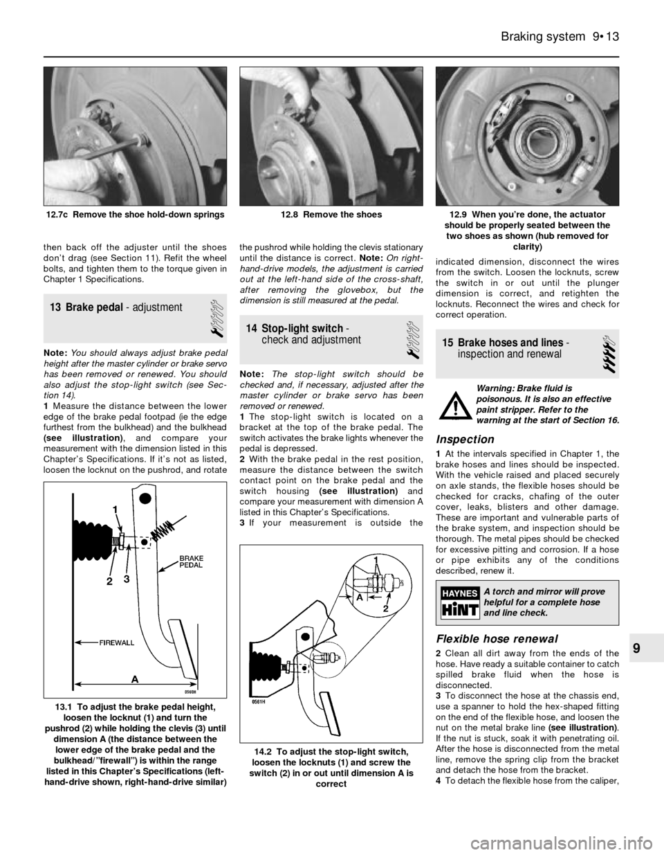
1Measure the distance between the lower
edge of the brake pedal footpad (ie the edge
furthest from the bulkhead) and the bulkhead
(see illustration), and compare your
measurement with the dimension listed in this
Chapter’s Specifications. If it’s not as listed,
loosen the locknut on the pushrod, and rotatethe pushrod while holding the clevis stationary
until the distance is correct. Note:On right-
hand-drive models, the adjustment is carried
out at the left-hand side of the cross-shaft,
after removing the glovebox, but the
dimension is still measured at the pedal.
14 Stop-light switch-
check and adjustment
1
Note:The stop-light switch should be
checked and, if necessary, adjusted after the
master cylinder or brake servo has been
removed or renewed.
1The stop-light switch is located on a
bracket at the top of the brake pedal. The
switch activates the brake lights whenever the
pedal is depressed.
2With the brake pedal in the rest position,
measure the distance between the switch
contact point on the brake pedal and the
switch housing (see illustration)and
compare your measurement with dimension A
listed in this Chapter’s Specifications.
3If your measurement is outside theindicated dimension, disconnect the wires
from the switch. Loosen the locknuts, screw
the switch in or out until the plunger
dimension is correct, and retighten the
locknuts. Reconnect the wires and check for
correct operation.
15 Brake hoses and lines-
inspection and renewal
4
Warning: Brake fluid is
poisonous. It is also an effective
paint stripper. Refer to the
warning at the start of Section 16.
Inspection
1At the intervals specified in Chapter 1, the
brake hoses and lines should be inspected.
With the vehicle raised and placed securely
on axle stands, the flexible hoses should be
checked for cracks, chafing of the outer
cover, leaks, blisters and other damage.
These are important and vulnerable parts of
the brake system, and inspection should be
thorough. The metal pipes should be checked
for excessive pitting and corrosion. If a hose
or pipe exhibits any of the conditions
described, renew it.
Flexible hose renewal
2Clean all dirt away from the ends of the
hose. Have ready a suitable container to catch
spilled brake fluid when the hose is
disconnected.
3To disconnect the hose at the chassis end,
use a spanner to hold the hex-shaped fitting
on the end of the flexible hose, and loosen the
nut on the metal brake line (see illustration).
If the nut is stuck, soak it with penetrating oil.
After the hose is disconnected from the metal
line, remove the spring clip from the bracket
and detach the hose from the bracket.
4To detach the flexible hose from the caliper,
Braking system 9•13
12.9 When you’re done, the actuator
should be properly seated between the
two shoes as shown (hub removed for
clarity)12.8 Remove the shoes12.7c Remove the shoe hold-down springs
14.2 To adjust the stop-light switch,
loosen the locknuts (1) and screw the
switch (2) in or out until dimension A is
correct
13.1 To adjust the brake pedal height,
loosen the locknut (1) and turn the
pushrod (2) while holding the clevis (3) until
dimension A (the distance between the
lower edge of the brake pedal and the
bulkhead/”firewall”) is within the range
listed in this Chapter’s Specifications (left-
hand-drive shown, right-hand-drive similar)
9
A torch and mirror will prove
helpful for a complete hose
and line check.
Page 203 of 228

REF•2MOT Test Checks
Seat belts and seats
Note: The following checks are applicable to
all seat belts, front and rear.
MExamine the webbing of all the belts
(including rear belts if fitted) for cuts, serious
fraying or deterioration. Fasten and unfasten
each belt to check the buckles. If applicable,
check the retracting mechanism. Check the
security of all seat belt mountings accessible
from inside the vehicle.
MThe front seats themselves must be
securely attached and the backrests must
lock in the upright position.
Doors
MBoth front doors must be able to be opened
and closed from outside and inside, and must
latch securely when closed.
Vehicle identification
MNumber plates must be in good condition,
secure and legible, with letters and numbers
correctly spaced – spacing at (A) should be
twice that at (B).
MThe VIN plate and/or homologation plate
must be legible.
Electrical equipment
MSwitch on the ignition and check the
operation of the horn.
MCheck the windscreen washers and wipers,
examining the wiper blades; renew damaged
or perished blades. Also check the operation
of the stop-lights.
MCheck the operation of the sidelights and
number plate lights. The lenses and reflectors
must be secure, clean and undamaged.
MCheck the operation and alignment of the
headlights. The headlight reflectors must not
be tarnished and the lenses must be
undamaged.
MSwitch on the ignition and check the
operation of the direction indicators (including
the instrument panel tell-tale) and the hazard
warning lights. Operation of the sidelights and
stop-lights must not affect the indicators - if it
does, the cause is usually a bad earth at the
rear light cluster.
MCheck the operation of the rear foglight(s),
including the warning light on the instrument
panel or in the switch.
Footbrake
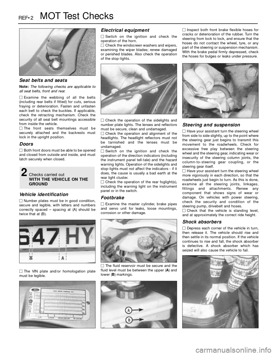
MExamine the master cylinder, brake pipes
and servo unit for leaks, loose mountings,
corrosion or other damage.
MThe fluid reservoir must be secure and the
fluid level must be between the upper (A) and
lower (B) markings.MInspect both front brake flexible hoses for
cracks or deterioration of the rubber. Turn the
steering from lock to lock, and ensure that the
hoses do not contact the wheel, tyre, or any
part of the steering or suspension mechanism.
With the brake pedal firmly depressed, check
the hoses for bulges or leaks under pressure.
Steering and suspension
MHave your assistant turn the steering wheel
from side to side slightly, up to the point where
the steering gear just begins to transmit this
movement to the roadwheels. Check for
excessive free play between the steering
wheel and the steering gear, indicating wear or
insecurity of the steering column joints, the
column-to-steering gear coupling, or the
steering gear itself.
MHave your assistant turn the steering wheel
more vigorously in each direction, so that the
roadwheels just begin to turn. As this is done,
examine all the steering joints, linkages,
fittings and attachments. Renew any
component that shows signs of wear or
damage. On vehicles with power steering,
check the security and condition of the
steering pump, drivebelt and hoses.
MCheck that the vehicle is standing level,
and at approximately the correct ride height.
Shock absorbers
MDepress each corner of the vehicle in turn,
then release it. The vehicle should rise and
then settle in its normal position. If the vehicle
continues to rise and fall, the shock absorber
is defective. A shock absorber which has
seized will also cause the vehicle to fail.
2Checks carried out
WITH THE VEHICLE ON THE
GROUND
Page 211 of 228

REF•10Fault Finding
Engine will not rotate when attempting to start
m mBattery terminal connections loose or corroded (Chapter 1).
m mBattery discharged or faulty (Chapter 1).
m mAutomatic transmission not completely engaged in Park (Chap-
ter 7B) or (on models with a clutch switch) clutch not completely
depressed (Chapter 8).
m mBroken, loose or disconnected wiring in the starting circuit
(Chapters 5 and 12).
m mStarter motor pinion jammed in flywheel ring gear (Chapter 5).
m mStarter solenoid faulty (Chapter 5).
m mStarter motor faulty (Chapter 5).
m mIgnition switch faulty (Chapter 12).
m mStarter pinion or flywheel teeth worn or broken (Chapter 5).
m mEngine internal problem (Chapter 2B).
Engine rotates, but will not start
m
mFuel tank empty.
m mBattery discharged (engine rotates slowly) (Chapter 5).
m mBattery terminal connections loose or corroded (Chapter 1).
m mLeaking fuel injector(s), faulty fuel pump, pressure regulator, etc
(Chapter 4).
m mFuel not reaching fuel injection system or carburettor (Chapter 4).
m mIgnition components damp or damaged (Chapter 5).
m mFuel injector stuck open (Chapter 4).
m mWorn, faulty or incorrectly-gapped spark plugs (Chapter 1).
m mBroken, loose or disconnected wiring in the starting circuit
(Chapter 5).
m mLoose distributor mounting bolts causing ignition timing to wander
(Chapters 1 and 5).
m mBroken, loose or disconnected wires at the ignition coil, or faulty
coil (Chapter 5).
Engine hard to start when cold
m mBattery discharged (Chapter 1).
m mFuel system malfunctioning (Chapter 4).
m mInjector(s) leaking or carburettor automatic choke faulty (Chap-
ter 4).
m mDistributor rotor carbon-tracked (Chapter 5).
Engine hard to start when hot
m
mAir filter element clogged (Chapter 1).
m mFuel not reaching the fuel injection system or carburettor (Chap-
ter 4).
m mCorroded battery connections, especially earth (negative)
connection (Chapter 1).
Starter motor noisy or excessively-rough in
engagement
m mPinion or flywheel gear teeth worn or broken (Chapter 5).
m mStarter motor mounting bolts loose or missing (Chapter 5).
Engine starts, but stops immediately
m
mLoose or faulty electrical connections at distributor, coil or
alternator (Chapter 5).
m mInsufficient fuel reaching the fuel injector(s) or carburettor
(Chapters 1 and 4).
m mDamaged fuel injection system speed sensors (Chapter 5).
m mFaulty fuel injection relays (Chapter 5).
Oil puddle under engine
m
mOil sump gasket and/or sump drain plug seal leaking (Chapter 2).
m mOil pressure sender unit leaking (Chapter 2).
m mValve cover gaskets leaking (Chapter 2).
m mEngine oil seals leaking (Chapter 2).
Engine idles erratically
m
mVacuum leakage (Chapter 4).
m mAir filter element clogged (Chapter 1).
m mFuel pump not delivering sufficient fuel to the fuel injection system
or carburettor (Chapter 4).
m mLeaking head gasket (Chapter 2).
m mTiming belt/chain and/or sprockets worn (Chapter 2).
m mCamshaft lobes worn (Chapter 2).
m mFaulty charcoal canister, where fitted (Chapter 6). This Section provides an easy-reference guide to the more
common problems which may occur during the operation of your
vehicle. These problems and their possible causes are grouped under
headings denoting various components or systems, such as Engine,
Cooling system, etc. They also refer you to the Chapter and/or
Section which deals with the problem.
Remember that successful fault diagnosis is not a mysterious
black art practised only by professional mechanics. It is simply the
result of the right knowledge combined with an intelligent, systematic
approach to the problem. Always work by a process of elimination,
starting with the simplest solution and working through to the mostcomplex - and never overlook the obvious. Anyone can run the fuel
tank dry or leave the lights on overnight, so don’t assume that you are
exempt from such oversights.
Finally, always establish a clear idea of why a problem has
occurred, and take steps to ensure that it doesn’t happen again. If the
electrical system fails because of a poor connection, check all other
connections in the system to make sure that they don’t fail as well. If a
particular fuse continues to blow, find out why - don’t just renew one
fuse after another. Remember, failure of a small component can often
be indicative of potential failure or incorrect functioning of a more
important component or system.
Engine