wiring diagram BMW 3 SERIES 2001 E46 TV Function Retrofit Kit Installation Instruction Manual
[x] Cancel search | Manufacturer: BMW, Model Year: 2001, Model line: 3 SERIES, Model: BMW 3 SERIES 2001 E46Pages: 16, PDF Size: 0.55 MB
Page 2 of 16

EN/2
Retrofit kit No. 65 50 0 143 549
Installation Instructions No. 01 29 0 143 558 Issue date: 03.2002
Contents
SectionPage
Important information . . . . . . . . . . . . . . . . . . . . . . . . . . . . . . . . . . . . . . . . . . . . . . . . . . . . . . . . . . . . . . . . . . 3
1. Preparations . . . . . . . . . . . . . . . . . . . . . . . . . . . . . . . . . . . . . . . . . . . . . . . . . . . . . . . . . . . . . . . . . . . . . . . . . . 4
2. Parts list . . . . . . . . . . . . . . . . . . . . . . . . . . . . . . . . . . . . . . . . . . . . . . . . . . . . . . . . . . . . . . . . . . . . . . . . . . . . . 5
3. Installation and cabling diagram . . . . . . . . . . . . . . . . . . . . . . . . . . . . . . . . . . . . . . . . . . . . . . . . . . . . . . . . . 6
4. Connection diagram for TV function . . . . . . . . . . . . . . . . . . . . . . . . . . . . . . . . . . . . . . . . . . . . . . . . . . . . . 7
5. To adjust the shock absorbers on both sides (cars without towing hitch only) . . . . . . . . . . . . . . . . 8
6. To install the aerial . . . . . . . . . . . . . . . . . . . . . . . . . . . . . . . . . . . . . . . . . . . . . . . . . . . . . . . . . . . . . . . . . . . . 9
7. To install and connect the TV function wiring harness; to install the video module . . . . . . . . . . . . 12
8. Concluding work and coding . . . . . . . . . . . . . . . . . . . . . . . . . . . . . . . . . . . . . . . . . . . . . . . . . . . . . . . . . . . 14
9. Wiring diagram for TV function . . . . . . . . . . . . . . . . . . . . . . . . . . . . . . . . . . . . . . . . . . . . . . . . . . . . . . . . . 15
Page 7 of 16

EN/7
Retrofit kit No. 65 50 0 143 549
Installation Instructions No. 01 29 0 143 558 Issue date: 03.2002
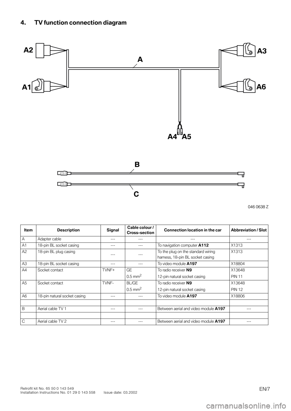
4. TV function connection diagram
0
0
Item Description SignalCable colour /
Cross-sectionConnection location in the car Abbreviation / Slot
A Adapter cable --- --- --- ---
A1 18-pin BL socket casing --- --- To navigation computer
A112
X1313
A2 18-pin BL plug casing
--- ---To the plug on the standard wiring
harness, 18-pin BL socket casingX1313
A3 18-pin BL socket casing --- --- To video module
A197
X18804
A4 Socket contact TVNF+ GE
0.5 mm
2
To radio receiver
N9
12-pin natural socket casing
X13648
PIN 11
A5 Socket contact TVNF- BL/GE
0.5 mm
2
To radio receiver
N9
12-pin natural socket casing
X13648
PIN 12
A6 18-pin natural socket casing --- --- To video module
A197
X18806
B Aerial cable TV 1 --- --- Between aerial and video module
A197
---
C Aerial cable TV 2 --- --- Between aerial and video module
A197
---
046 0638 Z
A3
A1A6
A4
A2
A5
C
B
A
Page 16 of 16

EN/16Retrofit kit No. 65 50 0 143 549
Installation Instructions No. 01 29 0 143 558 Issue date: 03.2002
9. TV function circuit diagram
Legend
Cable coloursA112Navigation computer
A197Video module
N9Radio receiver
X1313 Blue 18-pin socket casing on the navigation computer and blue 18-pin plug casing to the
standard wiring harness
X13016Terminal 31 connector
X13317Terminal 30 connector
X1364812-pin natural socket casing on the radio receiver
X18344I bus connector
X18804Blue 18-pin plug on the video module
X18806Natural coloured 18-pin plug on the video module
RT red
SW black
GN green
BR brown
GE yellow
WS white
BL blue