ignition BMW 3 SERIES 2004 E46 CPT8000 Electrical Connectors And Wiring Diagrams Workshop Manual
[x] Cancel search | Manufacturer: BMW, Model Year: 2004, Model line: 3 SERIES, Model: BMW 3 SERIES 2004 E46Pages: 9, PDF Size: 0.84 MB
Page 2 of 9

--------------- BMW CPT8000 Training & Troubleshooting Manual ---------------
Version 2.01 8/29/2001
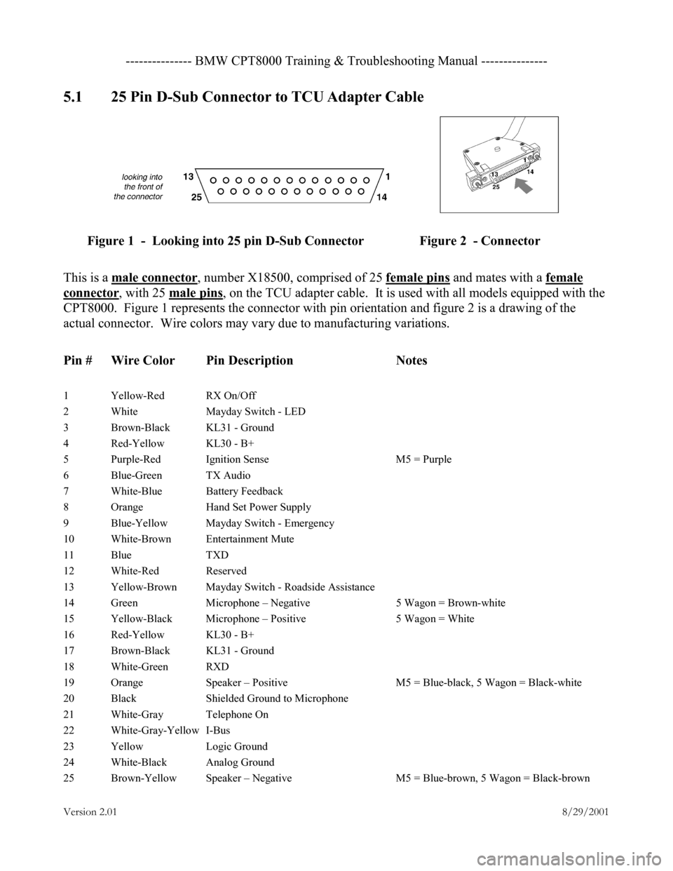
5.1 25 Pin D-Sub Connector to TCU Adapter Cable
Figure 1 - Looking into 25 pin D-Sub Connector Figure 2 - Connector
This is a male connector
, number X18500, comprised of 25 female pins and mates with a female
connector, with 25 male pins, on the TCU adapter cable. It is used with all models equipped with the
CPT8000. Figure 1 represents the connector with pin orientation and figure 2 is a drawing of the
actual connector. Wire colors may vary due to manufacturing variations.
Pin # Wire Color Pin Description Notes
1 Yellow-Red RX On/Off
2 White Mayday Switch - LED
3 Brown-Black KL31 - Ground
4 Red-Yellow KL30 - B+
5 Purple-Red Ignition Sense M5 = Purple
6 Blue-Green TX Audio
7 White-Blue Battery Feedback
8 Orange Hand Set Power Supply
9 Blue-Yellow Mayday Switch - Emergency
10 White-Brown Entertainment Mute
11 Blue TXD
12 White-Red Reserved
13 Yellow-Brown Mayday Switch - Roadside Assistance
14 Green Microphone – Negative 5 Wagon = Brown-white
15 Yellow-Black Microphone – Positive 5 Wagon = White
16 Red-Yellow KL30 - B+
17 Brown-Black KL31 - Ground
18 White-Green RXD
19 Orange Speaker – Positive M5 = Blue-black, 5 Wagon = Black-white
20 Black Shielded Ground to Microphone
21 White-Gray Telephone On
22 White-Gray-Yellow I-Bus
23 Yellow Logic Ground
24 White-Black Analog Ground
25 Brown-Yellow Speaker – Negative M5 = Blue-brown, 5 Wagon = Black-brown
Page 4 of 9

--------------- BMW CPT8000 Training & Troubleshooting Manual ---------------
Version 2.01 8/29/2001
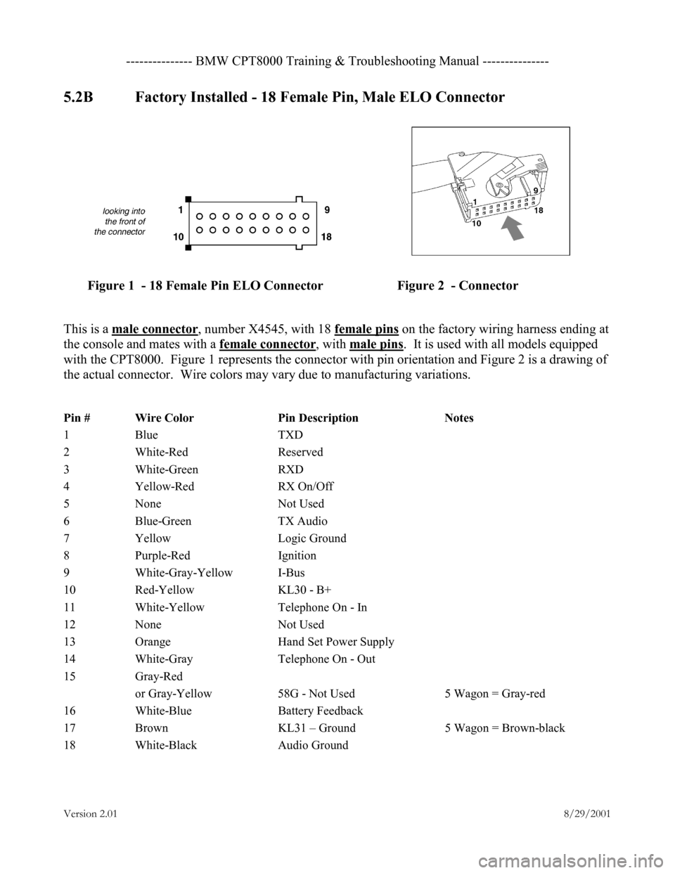
5.2B Factory Installed - 18 Female Pin, Male ELO Connector
Figure 1 - 18 Female Pin ELO Connector Figure 2 - Connector
This is a male connector
, number X4545, with 18 female pins on the factory wiring harness ending at
the console and mates with a female connector
, with male pins. It is used with all models equipped
with the CPT8000. Figure 1 represents the connector with pin orientation and Figure 2 is a drawing of
the actual connector. Wire colors may vary due to manufacturing variations.
Pin # Wire Color Pin Description Notes
1 Blue TXD
2 White-Red Reserved
3 White-Green RXD
4 Yellow-Red RX On/Off
5 None Not Used
6 Blue-Green TX Audio
7 Yellow Logic Ground
8 Purple-Red Ignition
9 White-Gray-Yellow I-Bus
10 Red-Yellow KL30 - B+
11 White-Yellow Telephone On - In
12 None Not Used
13 Orange Hand Set Power Supply
14 White-Gray Telephone On - Out
15 Gray-Red
or Gray-Yellow 58G - Not Used 5 Wagon = Gray-red
16 White-Blue Battery Feedback
17 Brown KL31 – Ground 5 Wagon = Brown-black
18 White-Black Audio Ground
Page 5 of 9

--------------- BMW CPT8000 Training & Troubleshooting Manual ---------------
Version 2.01 8/29/2001
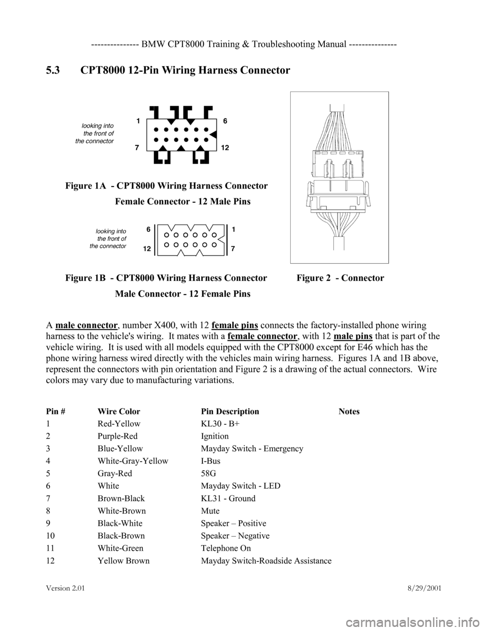
5.3 CPT8000 12-Pin Wiring Harness Connector
Figure 1A - CPT8000 Wiring Harness Connector Female Connector - 12 Male Pins
Figure 1B - CPT8000 Wiring Harness Connector Figure 2 - Connector Male Connector - 12 Female Pins
A male connector
, number X400, with 12 female pins connects the factory-installed phone wiring
harness to the vehicle's wiring. It mates with a female connector
, with 12 male pins that is part of the
vehicle wiring. It is used with all models equipped with the CPT8000 except for E46 which has the
phone wiring harness wired directly with the vehicles main wiring harness. Figures 1A and 1B above,
represent the connectors with pin orientation and Figure 2 is a drawing of the actual connectors. Wire
colors may vary due to manufacturing variations.
Pin # Wire Color Pin Description Notes
1 Red-Yellow KL30 - B+
2 Purple-Red Ignition
3 Blue-Yellow Mayday Switch - Emergency
4 White-Gray-Yellow I-Bus
5 Gray-Red 58G
6 White Mayday Switch - LED
7 Brown-Black KL31 - Ground
8 White-Brown Mute
9 Black-White Speaker – Positive
10 Black-Brown Speaker – Negative
11 White-Green Telephone On
12 Yellow Brown Mayday Switch-Roadside Assistance
Page 7 of 9

--------------- BMW CPT8000 Training & Troubleshooting Manual ---------------
Version 2.01 8/29/2001
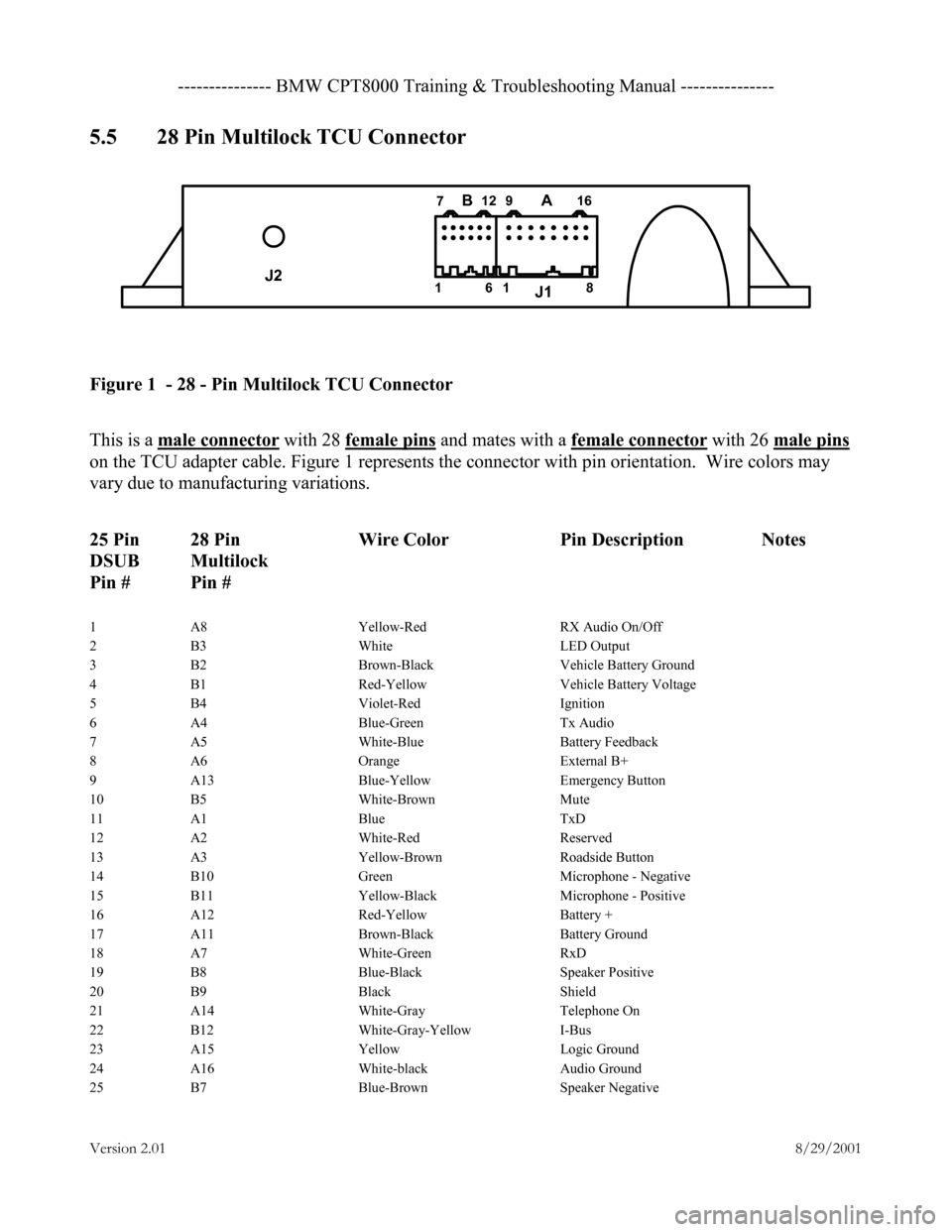
5.5 28 Pin Multilock TCU Connector
Figure 1 - 28 - Pin Multilock TCU Connector
This is a male connector with 28 female pins and mates with a female connector with 26 male pins
on the TCU adapter cable. Figure 1 represents the connector with pin orientation. Wire colors may
vary due to manufacturing variations.
25 Pin 28 Pin Wire Color Pin Description Notes
DSUB Multilock
Pin # Pin #
1 A8 Yellow-Red RX Audio On/Off
2 B3 White LED Output
3 B2 Brown-Black Vehicle Battery Ground
4 B1 Red-Yellow Vehicle Battery Voltage
5 B4 Violet-Red Ignition
6 A4 Blue-Green Tx Audio
7 A5 White-Blue Battery Feedback
8 A6 Orange External B+
9 A13 Blue-Yellow Emergency Button
10 B5 White-Brown Mute
11 A1 Blue TxD
12 A2 White-Red Reserved
13 A3 Yellow-Brown Roadside Button
14 B10 Green Microphone - Negative
15 B11 Yellow-Black Microphone - Positive
16 A12 Red-Yellow Battery +
17 A11 Brown-Black Battery Ground
18 A7 White-Green RxD
19 B8 Blue-Black Speaker Positive
20 B9 Black Shield
21 A14 White-Gray Telephone On
22 B12 White-Gray-Yellow I-Bus
23 A15 Yellow Logic Ground
24 A16 White-black Audio Ground
25 B7 Blue-Brown Speaker Negative
J2 J1
BA161 12
7 16
8
9