wiring BMW 3 SERIES 2005 E46 CPT8000 Electrical Connectors And Wiring Diagrams Workshop Manual
[x] Cancel search | Manufacturer: BMW, Model Year: 2005, Model line: 3 SERIES, Model: BMW 3 SERIES 2005 E46Pages: 9, PDF Size: 0.84 MB
Page 1 of 9

--------------- BMW CPT8000 Training & Troubleshooting Manual ---------------
Version 2.01 8/29/2001
5.0 CPT8000 Electrical Connectors and Wiring Diagrams
This section contains drawings of Electrical Connectors and information on Pin Configuration, Pin
Numbers, Wire Colors and Pin Descriptions.
5.1 25 Pin D-Sub Connector to TCU Adapter Cable
5.2A Eject Box Wiring Harness – 18 Male Pin, Female ELO Connector
5.2B Factory Installed – 18 Female Pin, Male ELO Connector
5.3 CPT8000 12-Pin Wiring Harness Connector
5.4 CPT8000 26-Pin ELO Connector for E46 Convertible
5.5 28-Pin Multilock TCU Connector
5.6A CPT8000 Wiring Diagram – All Models Except E46
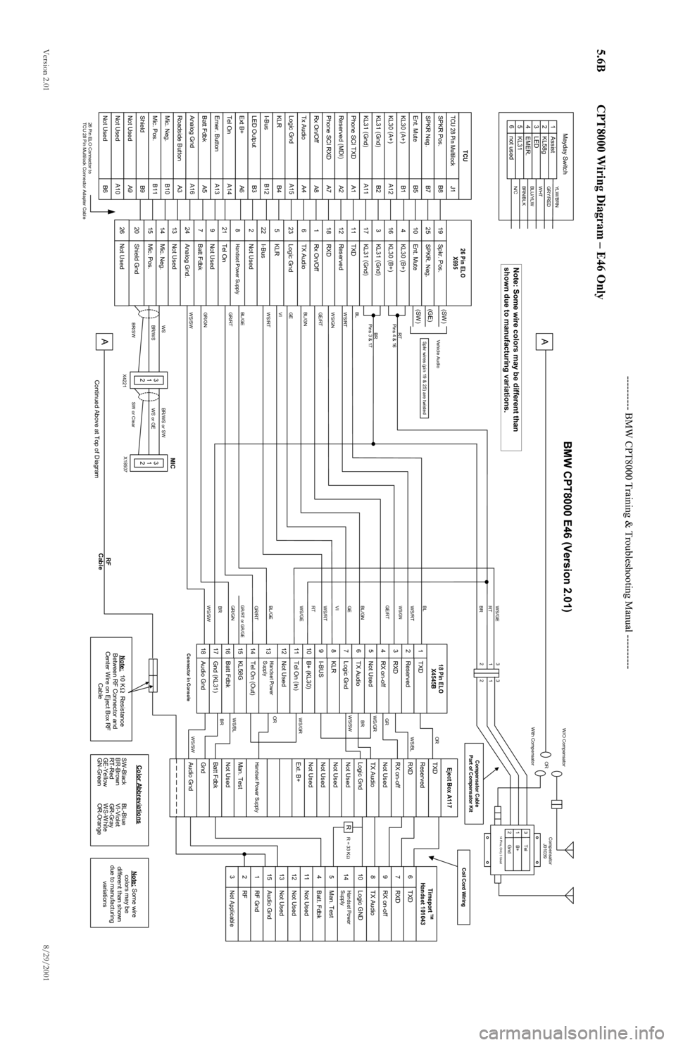
5.6B CPT8000 Wiring Diagram – E46 Only
Page 3 of 9
--------------- BMW CPT8000 Training & Troubleshooting Manual ---------------
Version 2.01 8/29/2001
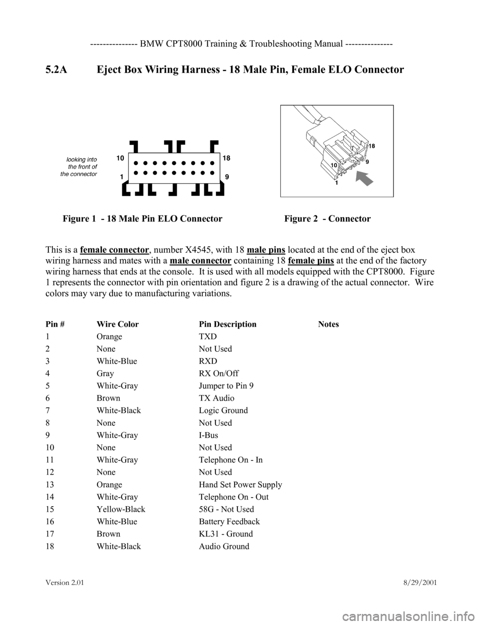
5.2A Eject Box Wiring Harness - 18 Male Pin, Female ELO Connector
Figure 1 - 18 Male Pin ELO Connector Figure 2 - Connector
This is a female connector
, number X4545, with 18 male pins located at the end of the eject box
wiring harness and mates with a male connector
containing 18 female pins at the end of the factory
wiring harness that ends at the console. It is used with all models equipped with the CPT8000. Figure
1 represents the connector with pin orientation and figure 2 is a drawing of the actual connector. Wire
colors may vary due to manufacturing variations.
Pin # Wire Color Pin Description Notes
1 Orange TXD
2 None Not Used
3 White-Blue RXD
4 Gray RX On/Off
5 White-Gray Jumper to Pin 9
6 Brown TX Audio
7 White-Black Logic Ground
8 None Not Used
9 White-Gray I-Bus
10 None Not Used
11 White-Gray Telephone On - In
12 None Not Used
13 Orange Hand Set Power Supply
14 White-Gray Telephone On - Out
15 Yellow-Black 58G - Not Used
16 White-Blue Battery Feedback
17 Brown KL31 - Ground
18 White-Black Audio Ground
Page 4 of 9
--------------- BMW CPT8000 Training & Troubleshooting Manual ---------------
Version 2.01 8/29/2001
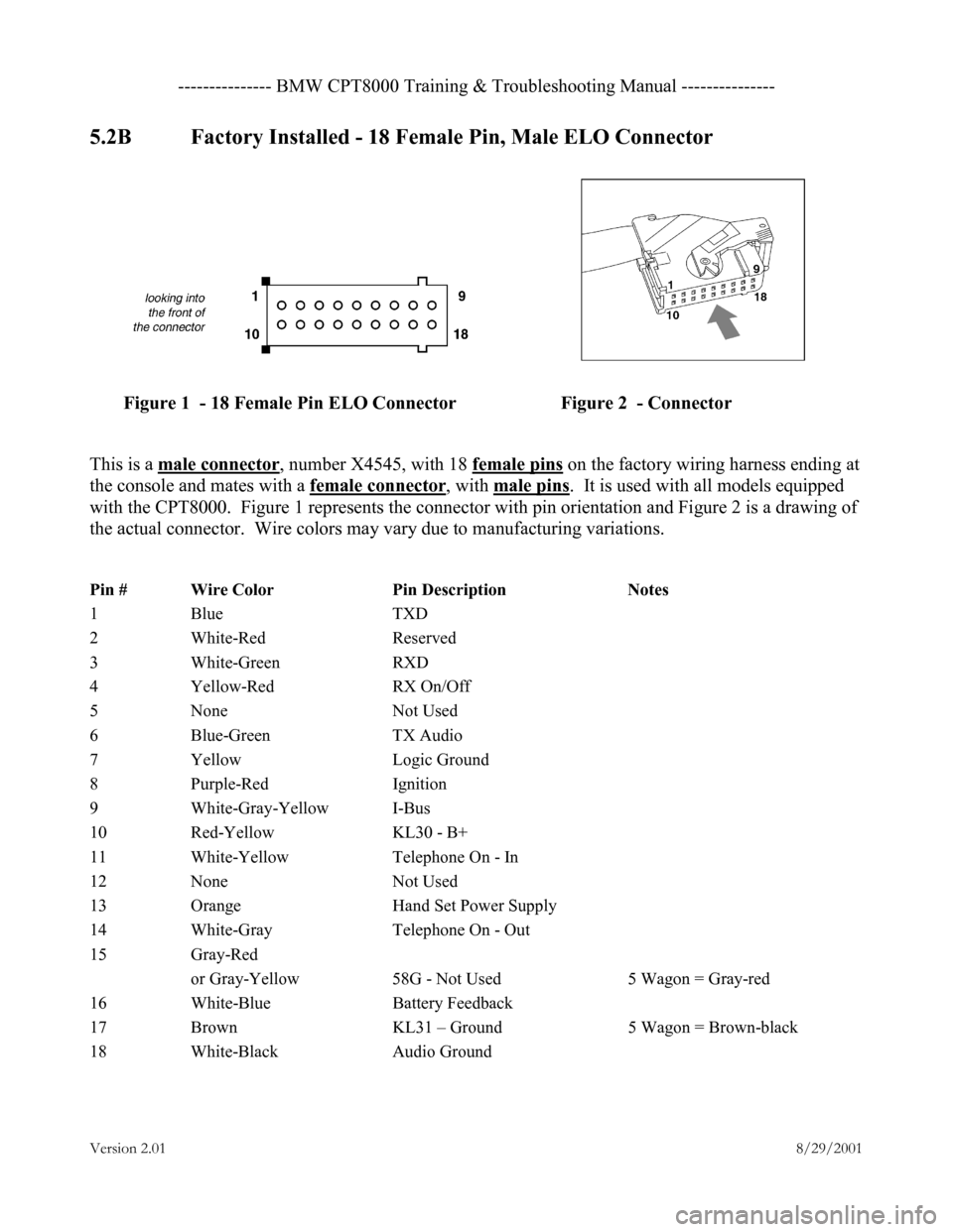
5.2B Factory Installed - 18 Female Pin, Male ELO Connector
Figure 1 - 18 Female Pin ELO Connector Figure 2 - Connector
This is a male connector
, number X4545, with 18 female pins on the factory wiring harness ending at
the console and mates with a female connector
, with male pins. It is used with all models equipped
with the CPT8000. Figure 1 represents the connector with pin orientation and Figure 2 is a drawing of
the actual connector. Wire colors may vary due to manufacturing variations.
Pin # Wire Color Pin Description Notes
1 Blue TXD
2 White-Red Reserved
3 White-Green RXD
4 Yellow-Red RX On/Off
5 None Not Used
6 Blue-Green TX Audio
7 Yellow Logic Ground
8 Purple-Red Ignition
9 White-Gray-Yellow I-Bus
10 Red-Yellow KL30 - B+
11 White-Yellow Telephone On - In
12 None Not Used
13 Orange Hand Set Power Supply
14 White-Gray Telephone On - Out
15 Gray-Red
or Gray-Yellow 58G - Not Used 5 Wagon = Gray-red
16 White-Blue Battery Feedback
17 Brown KL31 – Ground 5 Wagon = Brown-black
18 White-Black Audio Ground
Page 5 of 9
--------------- BMW CPT8000 Training & Troubleshooting Manual ---------------
Version 2.01 8/29/2001
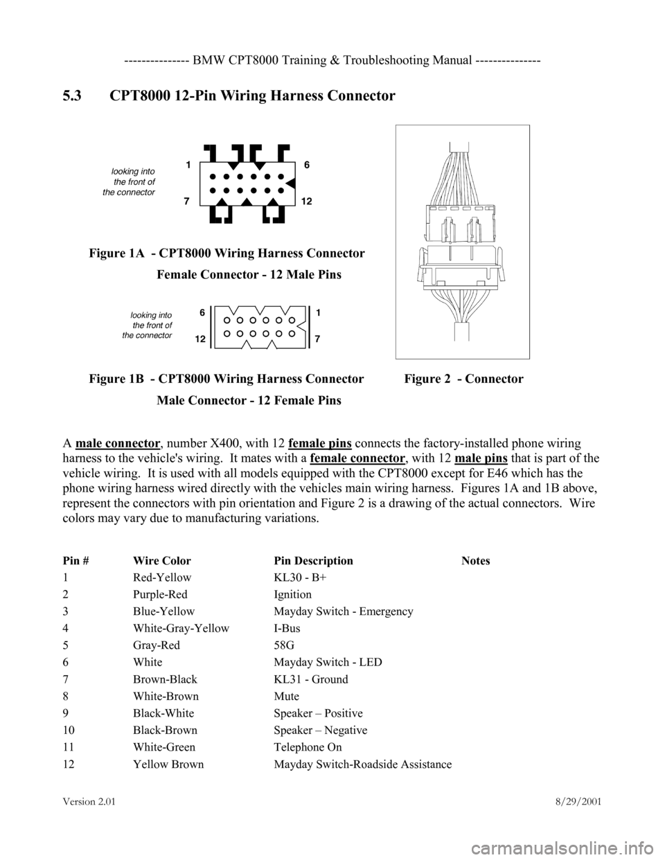
5.3 CPT8000 12-Pin Wiring Harness Connector
Figure 1A - CPT8000 Wiring Harness Connector Female Connector - 12 Male Pins
Figure 1B - CPT8000 Wiring Harness Connector Figure 2 - Connector Male Connector - 12 Female Pins
A male connector
, number X400, with 12 female pins connects the factory-installed phone wiring
harness to the vehicle's wiring. It mates with a female connector
, with 12 male pins that is part of the
vehicle wiring. It is used with all models equipped with the CPT8000 except for E46 which has the
phone wiring harness wired directly with the vehicles main wiring harness. Figures 1A and 1B above,
represent the connectors with pin orientation and Figure 2 is a drawing of the actual connectors. Wire
colors may vary due to manufacturing variations.
Pin # Wire Color Pin Description Notes
1 Red-Yellow KL30 - B+
2 Purple-Red Ignition
3 Blue-Yellow Mayday Switch - Emergency
4 White-Gray-Yellow I-Bus
5 Gray-Red 58G
6 White Mayday Switch - LED
7 Brown-Black KL31 - Ground
8 White-Brown Mute
9 Black-White Speaker – Positive
10 Black-Brown Speaker – Negative
11 White-Green Telephone On
12 Yellow Brown Mayday Switch-Roadside Assistance
Page 8 of 9
---------- BMW CPT8000 Training & Troubleshooting Manual ----------
Versio n 2 .01 8/29/2001
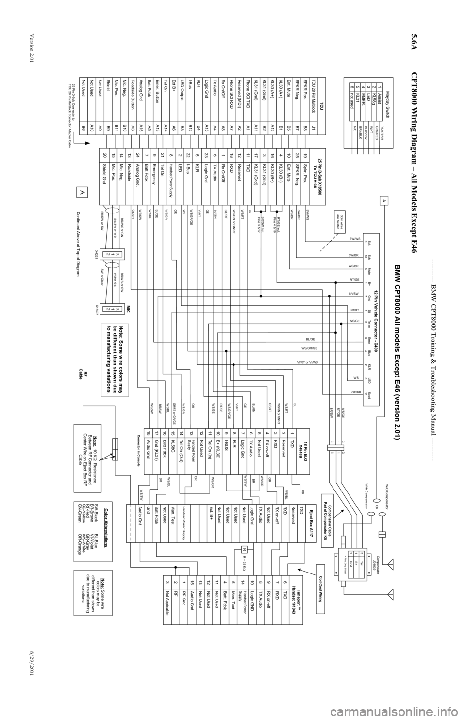
5.6A CPT8000 Wiring Diagram – All Models Except E46
TCU 28 Pin MultilockSPKR Pos.SPKR Neg.Ent. MuteKL30 (A+)KL31 (Gnd)KL30 (A+)KL31 (Gnd)Phone SCI TXDReserved (MDI)Phone SCI RXDTx AudioRx On/OffLogic GndKLRI-BusLED OutputExt B+Tel OnEmer. ButtonBatt FdbkAnalog GndRoadside ButtonMic. Neg.Mic. Pos.ShieldNot UsedNot UsedNot Used
B11B10A3A16B6A10A9B9B3B12B4A15A5A13A14A6A1A11B2A12A4A8A7A2B5B7B8J1B1
AssistKL58gLEDEMER.KL31not used
643215
YLW/BRNGRY/REDWHTBLU/YLWBRN/BLKN/C
Mayday Switch
25 Pin D-Sub Connector to
TCU 28 Pin Multilock Connector Adapter Cable
SPKR. Neg.Spkr. Pos.Ent. MuteKL30 (B+)KL30 (B+)KL31 (Gnd)TXDKL31 (Gnd)ReservedRXDRx On/OffTX AudioLogic GndKLRI-BusLEDHandset Power SupplyEmergencyBatt FdbkAnalog Gnd.RoadsideMic. Neg.Mic. Pos.Shield Gnd
247982015141361181222252341025191117316
Tel On
21
TCU
25 Pin D-Sub X18500
To TCU H-38
RXDTXDRX on-offTX AudioLogic GNDBatt. FdbkMan. TestNot UsedNot UsedNot UsedAudio GndRF GndRFNot Applicable
151312113218976451410
Timeport
TM
Handset 101043
ReservedTXDRXDNot UsedTX AudioLogic GndNot UsedNot UsedNot UsedNot UsedExt. B+Man. TestNot UsedHandset Power SupplyGndAudio GndBatt FdbkEject Box A117
Handset Power
Supply
RX on-off
R
ReservedTXDRXDNot UsedTX AudioLogic GndI-BUSKLRB+ (KL30)Tel On (In)Not UsedTel On (Out)KL58GBatt FdbkHandset Power
SupplyAudio GndGnd (KL31)18 Pin ELOX4545BRX on-offConnector in Console WS/SW
BRWS/BLORWS/GRWS/GRBRWS/SWGR
WS/BLOR
SW /W S
Spk
9
Spk
10Mute
8 B+
1Gnd
7
58
5
Tel on
11
Emer
3IBus
4 KLR
2LED
6 Road
12
12 Pin Vehicle Connector - X400
SW /BR
WS/BR
RT/GE Incl.Pins 4 & 16
BR/SW Incl. Pins 3 & 17
BL
WS/RT
W S/GN or GN/RT
GE/RT
BL/GN
GE
VI/RT
WS/SWWS/GR/GEOR
WS/GR
BL/GE
WS/BL
GE/BR
WS/GR RT/GE BL
WS/RTWS/GN or GN/RTGE
VI/RT
WS/GE
OR
GE/RT
BL/GNWS/BLBR/SW
WS/SWGR/RT or GR/GE
SW/WS
SW/BR
WS/BR RT/GE
BR/SW
GR/RT
WS/GE
BL/GE
WS
VI/RT or VI/WS
WS/GR/GE
GE/BR
WS/GE
RT/GE
BR/SW
A
3
1
2Tel
Gnd
B+14 Pins, Only 3 UsedCompensator
J01039
OR
W /O Compensator
W ith Compensator
Note: 10 K Resistance
Between RF Connector and
Center Wire on Eject Box RF Cable
BR/W S or GNGE/SW or WS
BR/SW or SW
3
1
2
BR/WS or SWWS or GE
SW or Clear
3
1
2
X4221 X18507
A
Continued Above at Top of Diagram
Ω
SW-Black
BR-Brown
RT-Red
GE-Yellow
GN-GreenBL-Blue
VI-Violet
GR-Gray
WS-White
OR-OrangeColor Abbreviations
Note:
Some wire
colors may be
different than shown
due to manufacturing variations
RF
Cable
Coil Cord Wiring
Compensator Cable
Part of Compensator Kit
Spkr wires
are twisted
MIC
WS
3
1
2 3
1
2
R = 33 K
Ω
123456789101112131415161718
WS/GR/GE
BMW CPT8000 All models Except E46 (version 2.01)
Note: Some wire colors may
be different than shown due
to manufacturing variations.
Page 9 of 9
---------- BMW CPT8000 Training & Troubleshooting Manual ----------
Versio n 2 .01 8/29/2001
5.6B CPT8000 Wiring Diagram – E46 Only
TCU 28 Pin MultilockSPKR Pos.SPKR Neg.Ent. MuteKL30 (A+)KL31 (Gnd)KL30 (A+)KL31 (Gnd)Phone SCI TXDReserved (MDI)Phone SCI RXDTx AudioRx On/OffLogic GndKLRI-BusLED OutputExt B+Tel OnEmer. ButtonBatt FdbkAnalog GndRoadside ButtonMic. Neg.Mic. Pos.ShieldNot UsedNot UsedNot Used
B11B10A3A16B6A10A9B9B3B12B4A15A5A13A14A6A1A11B2A12A4A8A7A2B5B7B8J1B1
AssistKL58gLEDEMER.KL31not used
643215
YLW /BRNGRY/REDWHTBLU/YLWBRN/BLKN/C
Mayday Switch
26 Pin ELO Connector to
TCU 28 Pin Multilock Connector Adapter Cable
SPKR. Neg.Spkr. Pos.Ent. MuteKL30 (B+)KL30 (B+)KL31 (Gnd)TXDKL31 (Gnd)ReservedRXDRx On/OffTX AudioLogic GndKLRI-BusNot UsedHandset Power SupplyNot UsedBatt FdbkAnalog Gnd.Not UsedMic. Neg.Mic. Pos.Shield Gnd
247982015141361181222252341025191117316
Tel On
21
TCU
26 Pin ELO
X695
RXDTXDRX on-offTX AudioLogic GNDBatt. FdbkMan. TestNot UsedNot UsedNot UsedAudio GndRF GndRFNot Applicable
151312113218976451410
Timeport
TM
Handset 101043
ReservedTXDRXDNot UsedTX AudioLogic GndNot UsedNot UsedNot UsedNot UsedExt. B+Man. TestNot UsedHandset Power SupplyGndAudio GndBatt FdbkEject Box A117
Handset Power
Supply
RX on-off
R
ReservedTXDRXDNot UsedTX AudioLogic GndI-BUSKLRB+ (KL30)Tel On (In)Not UsedTel On (Out)KL58GBatt FdbkHandset Power
SupplyAudio GndGnd (KL31)18 Pin ELOX4545BRX on-offConnector in Console WS/SW
BRWS/BLORWS/GRWS/GRBRWS/SWGR
WS/BLOR
RT
Pins 4 & 16BR
Pins 3 & 17
BL
WS/RT
WS/GN
GE/RT
BL/GN
GE
VI
WS/SWWS/RTBL/GE
GR/RT
GR/GN
GR/RT RT BL
WS/RTWS/GNGE
VI
WS/GE
BL/GE
GE/RT
BL/GNGR/GN BR
WS/SWGR/RT or GR/GEWS/GE
RT
BR
3
1
2 Tel
Gnd
B+14 Pins, Only 3 UsedCompensator
J01039
OR
W /O Compensator
With Compensator
Note: 10 K Resistance
Between RF Connector and
Center Wire on Eject Box RF
Cable
WSBR/W S
BR/SW
3
1
2
BR/W S or SWWS or GE
SW or Clear
3
1
2
X4221 X18507
A
Continued Above at Top of Diagram
Ω
SW-Black
BR-Brown
RT-Red
GE-Yellow
GN-GreenBL-Blue
VI-Violet
GR-Gray
WS-White
OR-OrangeColor Abbreviations
Note:
Some wire
colors may be
different than shown
due to manufacturing
variations
RF
Cable
Coil Cord Wiring
Compensator Cable
Part of Compensator Kit
Spkr wires (pin 19 & 25) are twisted
MIC
3
1
2 3
1
2
R = 33 K
Ω
123456789101112131415161718
WS/RT
BMW CPT8000 E46 (Version 2.01)
Not Used
26
Vehicle Audio
(SW )
(GE)
(SW )
A
Note: Some wire colors may be different than
shown due to manufacturing variations.