navigation BMW 3 SERIES 2005 E46 TV Function Retrofit Kit Installation Instruction Manual
[x] Cancel search | Manufacturer: BMW, Model Year: 2005, Model line: 3 SERIES, Model: BMW 3 SERIES 2005 E46Pages: 16, PDF Size: 0.55 MB
Page 4 of 16
EN/4
Retrofit kit No. 65 50 0 143 549
Installation Instructions No. 01 29 0 143 558 Issue date: 03.2002
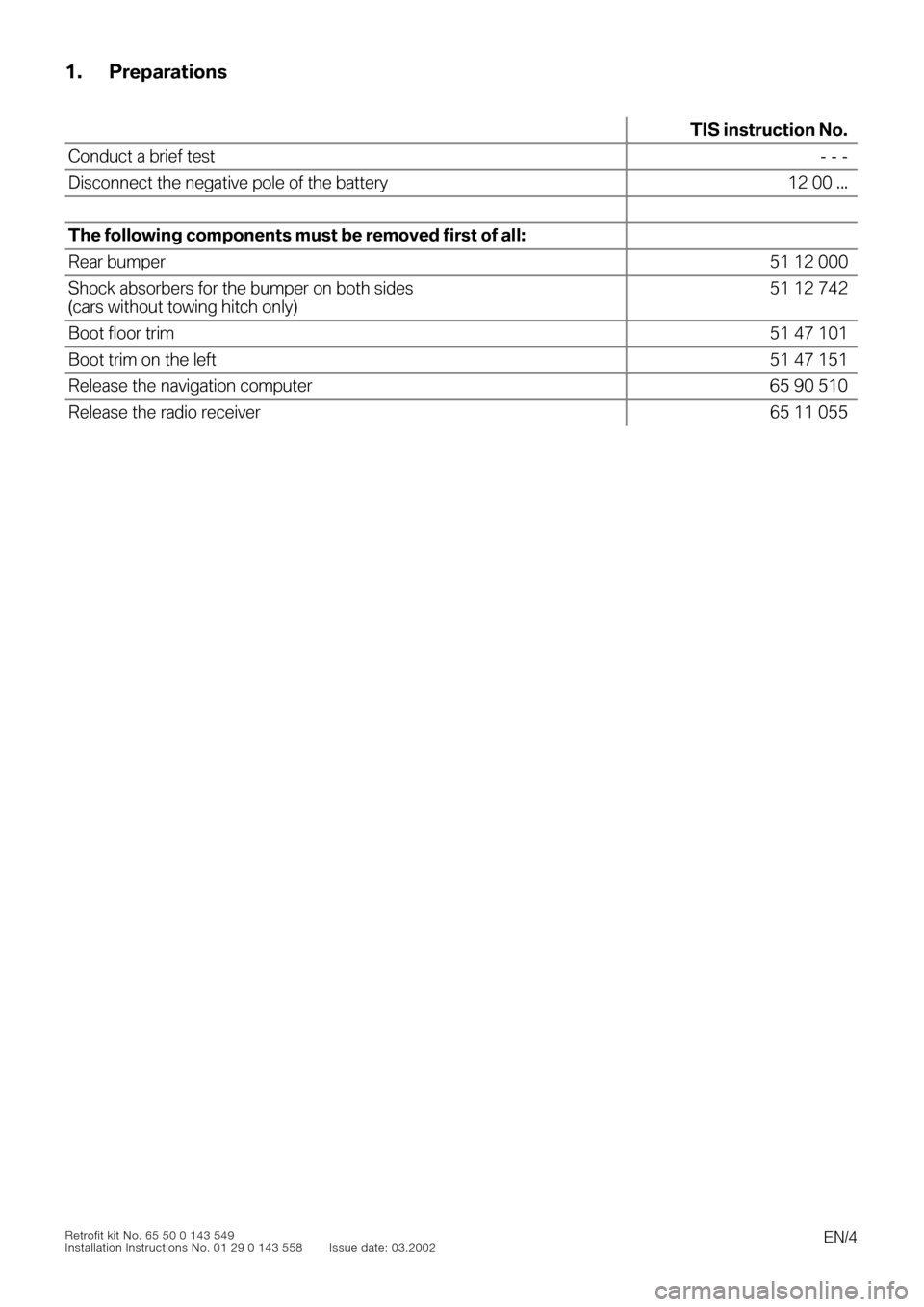
1. Preparations
0
TIS instruction No.
Conduct a brief test- - -
Disconnect the negative pole of the battery 12 00 ...
The following components must be removed first of all:
Rear bumper51 12 000
Shock absorbers for the bumper on both sides
(cars without towing hitch only)51 12 742
Boot floor trim51 47 101
Boot trim on the left51 47 151
Release the navigation computer 65 90 510
Release the radio receiver 65 11 055
Page 6 of 16
EN/6
Retrofit kit No. 65 50 0 143 549
Installation Instructions No. 01 29 0 143 558 Issue date: 03.2002
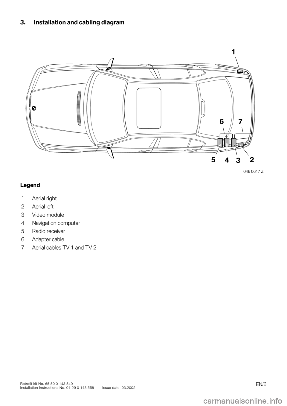
3. Installation and cabling diagram
0
Legend
1 Aerial right
2 Aerial left
3 Video module
4 Navigation computer
5 Radio receiver
6 Adapter cable
7 Aerial cables TV 1 and TV 2
1
5243
67
046 0617 Z
Page 7 of 16
EN/7
Retrofit kit No. 65 50 0 143 549
Installation Instructions No. 01 29 0 143 558 Issue date: 03.2002
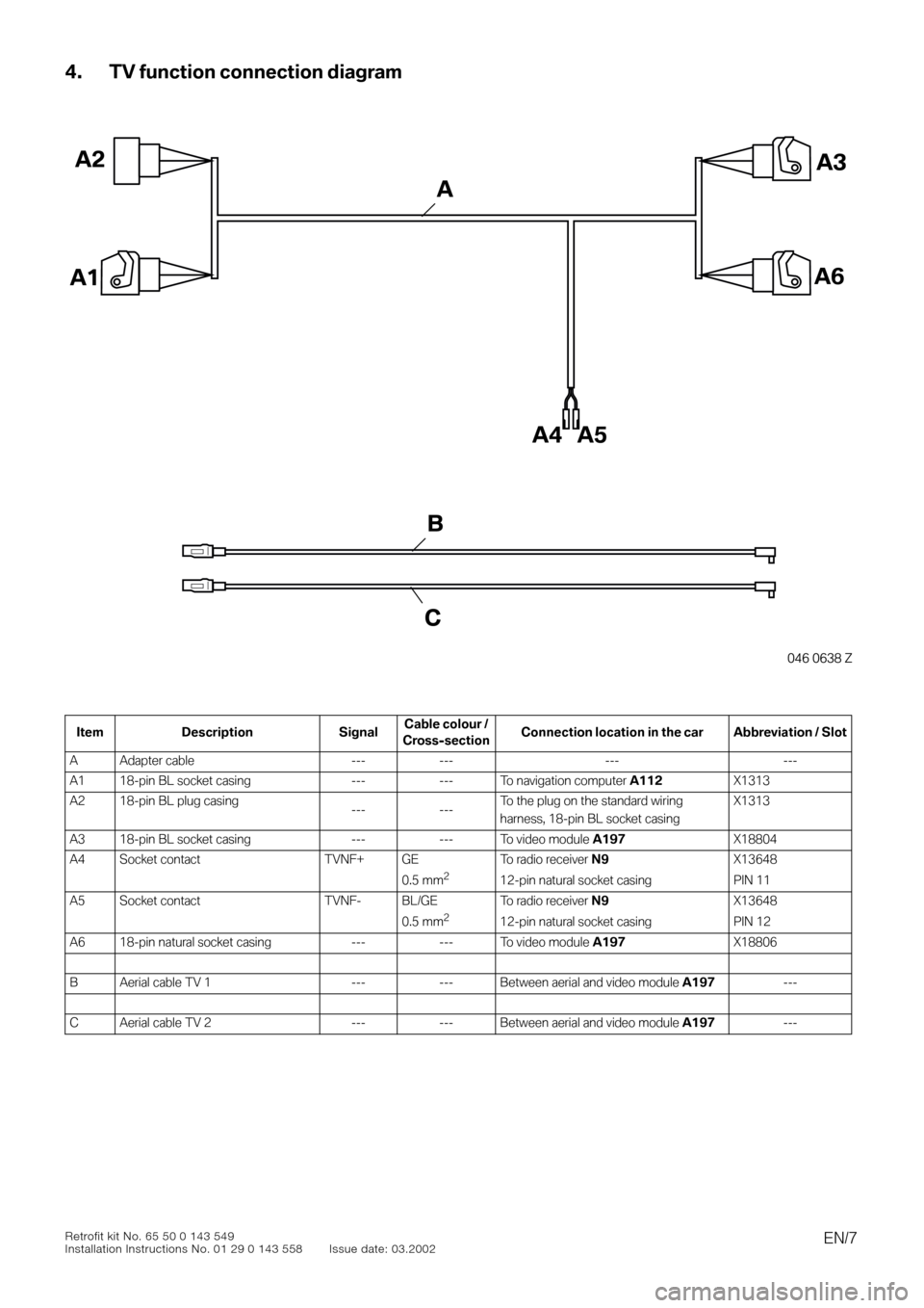
4. TV function connection diagram
0
0
Item Description SignalCable colour /
Cross-sectionConnection location in the car Abbreviation / Slot
A Adapter cable --- --- --- ---
A1 18-pin BL socket casing --- --- To navigation computer
A112
X1313
A2 18-pin BL plug casing
--- ---To the plug on the standard wiring
harness, 18-pin BL socket casingX1313
A3 18-pin BL socket casing --- --- To video module
A197
X18804
A4 Socket contact TVNF+ GE
0.5 mm
2
To radio receiver
N9
12-pin natural socket casing
X13648
PIN 11
A5 Socket contact TVNF- BL/GE
0.5 mm
2
To radio receiver
N9
12-pin natural socket casing
X13648
PIN 12
A6 18-pin natural socket casing --- --- To video module
A197
X18806
B Aerial cable TV 1 --- --- Between aerial and video module
A197
---
C Aerial cable TV 2 --- --- Between aerial and video module
A197
---
046 0638 Z
A3
A1A6
A4
A2
A5
C
B
A
Page 12 of 16
EN/12
Retrofit kit No. 65 50 0 143 549
Installation Instructions No. 01 29 0 143 558 Issue date: 03.2002
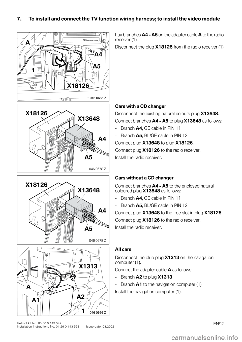
7. To install and connect the TV function wiring harness; to install the video module
0
0
0
00
Lay branches
A4 - A5
on the adapter cable
A
to the
radio
receiver (1).
Disconnect the plug
X18126
from the radio receiver (1).
0
Cars with a CD changer
Disconnect the existing natural colours plug
X13648
.
Connect branches
A4 - A5
to plug
X13648
as follows:
- Branch
A4
, GE cable in PIN 11
- Branch
A5
, BL/GE cable in PIN 12
Connect plug
X13648
to plug
X18126
.
Connect plug
X18126
to the radio receiver.
Install the radio receiver.
0Cars without a CD changer
Connect branches A4 - A5 to the enclosed natural
coloured plug X13648 as follows:
- Branch A4, GE cable in PIN 11
- Branch A5, BL/GE cable in PIN 12
Connect plug X13648 to the free slot in plug X18126.
Connect plug X18126 to the radio receiver.
Install the radio receiver.
0All cars
Disconnect the blue plug X1313 on the navigation
computer (1).
Connect the adapter cable A as follows:
- Branch A2 to plug X1313
- Branch A1 to the navigation computer (1)
Install the navigation computer (1).
046 0665 Z
GPSNAVIGATION SYSTEM
A4
A51
X18126
A
046 0678 Z
X18126
A4
X13648
A5
046 0678 Z
X18126
A4
X13648
A5
046 0666 Z
X1313
A2A1
A
1
Page 13 of 16
EN/13Retrofit kit No. 65 50 0 143 549
Installation Instructions No. 01 29 0 143 558 Issue date: 03.2002
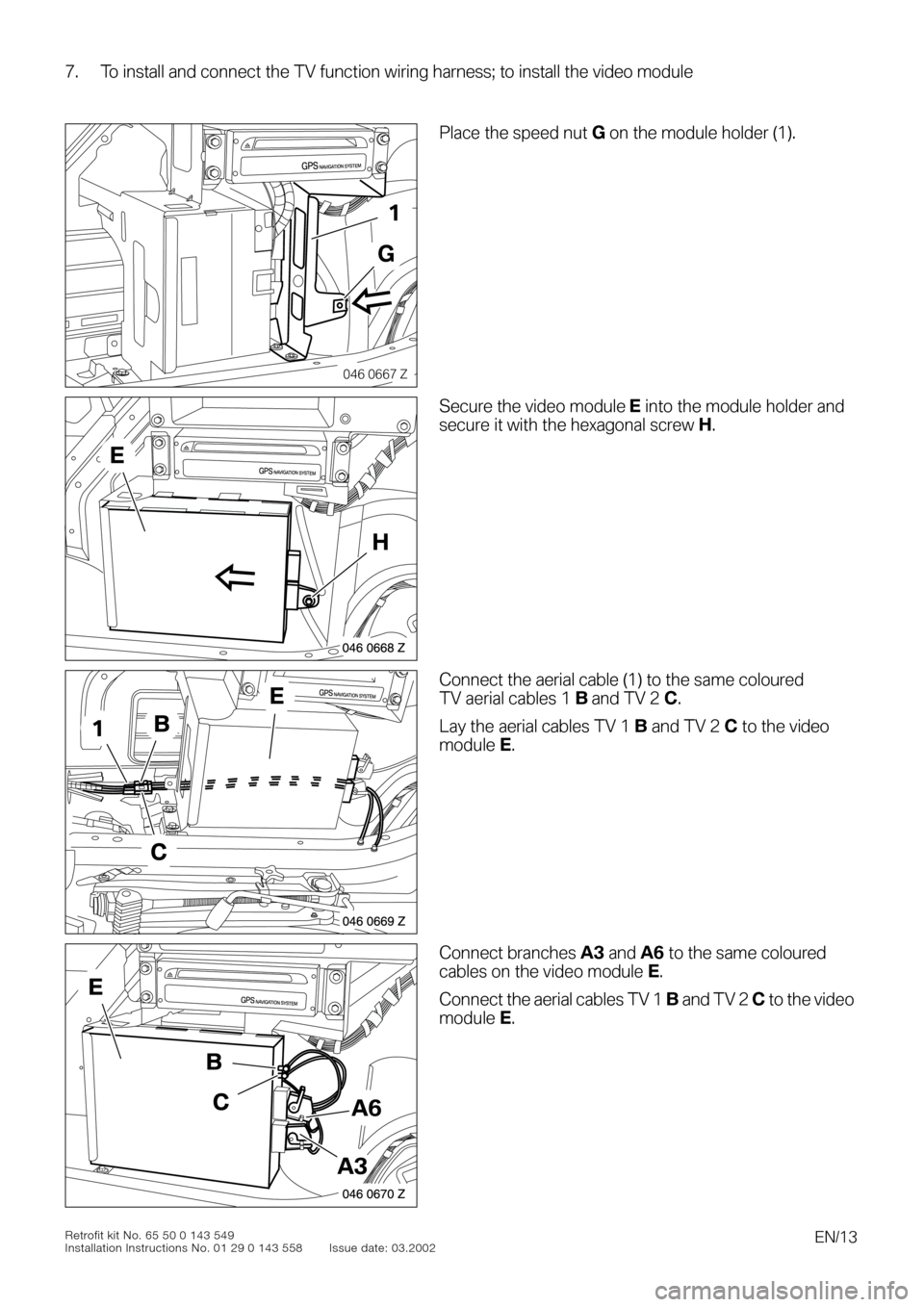
7. To install and connect the TV function wiring harness; to install the video module
0
0
0To install and connect the TV function wiring harness; to install the video module
00
Place the speed nut G on the module holder (1).
0Secure the video module E into the module holder and
secure it with the hexagonal screw H.
0Connect the aerial cable (1) to the same coloured
TV aerial cables 1 B and TV 2 C.
Lay the aerial cables TV 1 B and TV 2 C to the video
module E.
0Connect branches A3 and A6 to the same coloured
cables on the video module E.
Connect the aerial cables TV 1 B and TV 2 C to the video
module E.
046 0667 Z
GPSNAVIGATION SYSTEM
1
G
046 0668 Z
GPSNAVIGATION SYSTEM
H
E
046 0669 Z
GPSNAVIGATION SYSTEM
B1
C
E
046 0670 Z
GPSNAVIGATION SYSTEM
A3
A6
B
C
E
Page 16 of 16

EN/16Retrofit kit No. 65 50 0 143 549
Installation Instructions No. 01 29 0 143 558 Issue date: 03.2002
9. TV function circuit diagram
Legend
Cable coloursA112Navigation computer
A197Video module
N9Radio receiver
X1313 Blue 18-pin socket casing on the navigation computer and blue 18-pin plug casing to the
standard wiring harness
X13016Terminal 31 connector
X13317Terminal 30 connector
X1364812-pin natural socket casing on the radio receiver
X18344I bus connector
X18804Blue 18-pin plug on the video module
X18806Natural coloured 18-pin plug on the video module
RT red
SW black
GN green
BR brown
GE yellow
WS white
BL blue