long life BMW 3 SERIES GRAN COUPE 2014 F34 Owner's Manual
[x] Cancel search | Manufacturer: BMW, Model Year: 2014, Model line: 3 SERIES GRAN COUPE, Model: BMW 3 SERIES GRAN COUPE 2014 F34Pages: 246, PDF Size: 6.49 MB
Page 106 of 246
System limits
The system does not function properly if a re‐
set has not been carried out, e.g., a flat tire is
reported though tire inflation pressures are
correct.
The tire inflation pressure depends on the
tire's temperature. Driving or exposure to the
sun will increase the tire's temperature, thus
increasing the tire inflation pressure. The tire
inflation pressure is reduced when the tire
temperature falls again. These circumstances
may cause a warning when temperatures fall
very sharply.
Malfunction The yellow warning lamp flashes and
then lights up continuously. A Check
Control message is displayed. No flat
tire or loss of tire inflation pressure can be de‐
tected.
Display in the following situations:▷A wheel without TPM electronics is fitted:
have the service center check it if needed.▷Malfunction: have the system checked by
your service center.▷TPM was unable to complete the reset.
Reset the system again.▷Interference through systems or devices
with the same radio frequency: after leav‐
ing the area of the interference, the system
automatically becomes active again.
Declaration according to NHTSA/
FMVSS 138 Tire Pressure Monitoring
System
Each tire, including the spare (if provided)
should be checked monthly when cold and in‐
flated to the inflation pressure recommended
by the vehicle manufacturer on the vehicle
placard or tire inflation pressure label. (If your
vehicle has tires of a different size than the size
indicated on the vehicle placard or tire inflation
pressure label, you should determine the
proper tire inflation pressure for those tires.)
As an added safety feature, your vehicle has
been equipped with a tire pressure monitoring
system (TPMS) that illuminates a low tire pres‐
sure telltale when one or more of your tires is
significantly under-inflated. Accordingly, when
the low tire pressure telltale illuminates, you
should stop and check your tires as soon as
possible, and inflate them to the proper pres‐
sure. Driving on a significantly under-inflated
tire causes the tire to overheat and can lead to
tire failure. Under-inflation also reduces fuel ef‐
ficiency and tire tread life, and may affect the
vehicle's handling and stopping ability. Please
note that the TPMS is not a substitute for
proper tire maintenance, and it is the driver's
responsibility to maintain correct tire pressure,
even if under-inflation has not reached the
level to trigger illumination of the TPMS low
tire pressure telltale. Your vehicle has also
been equipped with a TPMS malfunction indi‐
cator to indicate when the system is not oper‐
ating properly. The TPMS malfunction indica‐
tor is combined with the low tire pressure
telltale. When the system detects a malfunc‐
tion, the telltale will flash for approximately one
minute and then remain continuously illumi‐
nated. This sequence will continue upon sub‐
sequent vehicle start-ups as long as the mal‐
function exists. When the malfunction indicator
is illuminated, the system may not be able to
detect or signal low tire pressure as intended.
TPMS malfunctions may occur for a variety of
reasons, including the installation of replace‐
ment or alternate tires or wheels on the vehicle
that prevent the TPMS from functioning prop‐
erly. Always check the TPMS malfunction tell‐
tale after replacing one or more tires or wheels
on your vehicle to ensure that the replacement
or alternate tires and wheels allow the TPMS
to continue to function properly.Seite 102ControlsSafety102
Online Edition for Part no. 01 40 2 956 806 - X/14
Page 172 of 246
Things to remember when drivingVehicle features and options
This chapter describes all standard, country-
specific and optional features offered with the
series. It also describes features that are not
necessarily available in your car, e. g., due to
the selected options or country versions. This
also applies to safety-related functions and
systems.
Breaking-in period
General information Moving parts need time to adjust to one an‐
other (break-in time).
The following instructions will help accomplish
a long vehicle life and good efficiency.
During break-in, do not use the Launch Con‐
trol, refer to page 74.
Engine, transmission, and axle drive Always obey the official speed limit.
Up to 1,200 miles/2,000 km
Do not exceed the maximum engine and road
speed:▷For gasoline engine 4,500 rpm and
100 mph/160 km/h.
Avoid full load or kickdown under all circum‐
stances.
From 1,200 miles/2,000 km The engine and vehicle speed can gradually be
increased.
Tires
Tire traction is not optimal due to manufactur‐
ing circumstances when tires are brand-new;
they achieve their full traction potential after a
break-in time.
Drive conservatively for the first
200 miles/300 km.
Brake system
Brakes require an initial break-in period of ap‐
prox. 300 miles/500 km to achieve optimal per‐
formance between brake discs and brake
pads. Drive moderately during this break-in pe‐
riod.
Following part replacement
The same break-in procedures should be ob‐
served if any of the components above-men‐
tioned have to be renewed in the course of the
vehicle's operating life.
General driving notes
Closing the tailgate Drive with the tailgate closed
Only drive with the tailgate closed; other‐
wise, in the event of an accident or braking and
evasive maneuvers, passengers and other traf‐
fic may be injured, and the vehicle may be
damaged. In addition, exhaust fumes may en‐
ter the vehicle interior.◀
If driving with the tailgate open cannot be
avoided:▷Close all windows and the glass sunroof.▷Greatly increase the air flow from the vents.▷Drive moderately.
Hot exhaust system
Hot exhaust system
High temperatures are generated in the
exhaust system.
Seite 168Driving tipsThings to remember when driving168
Online Edition for Part no. 01 40 2 956 806 - X/14
Page 179 of 246
Avoid high engine speeds
As a rule: driving at low engine speeds lowers
fuel consumption and reduces wear.
Use 1st gear to get the vehicle moving. Start‐
ing with the 2nd gear, accelerate rapidly. When
accelerating, shift up before reaching high en‐
gine speeds.
When you reach the desired speed, shift into
the highest applicable gear and drive with the
engine speed as low as possible and at a con‐
stant speed.
If necessary, observe the gear shift indicator of
the vehicle, refer to page 83.
Use coasting
When approaching a red light, take your foot
off the accelerator and let the vehicle coast to
a halt.
For going downhill take your foot off the accel‐
erator and let the vehicle roll.
The flow of fuel is interrupted while coasting.
Switch off the engine during longer stops
Switch off the engine during longer stops, e.g.,
at traffic lights, railroad crossings or in traffic
congestion.
Auto Start/Stop function The Auto Start/Stop function of your vehicle
automatically switches off the engine during a
stop.
If the engine is switched off and then restarted
rather than leaving the engine running con‐
stantly, fuel consumption and emissions are
reduced. Savings can begin within a few sec‐
onds of switching off the engine.
In addition, fuel consumption is also deter‐
mined by other factors, such as driving style,road conditions, maintenance or environmental
factors.
Switch off any functions that
are not currently needed
Functions such as seat heating and the rear
window defroster require a lot of energy and
reduce the range, especially in city and stop-
and-go traffic.
Reel off these functions if they are not needed. The ECO PRO driving program supports the
energy conserving use of comfort features.
These functions are automatically deactivated
partially or completely.
Have maintenance carriedout
Have vehicles maintained regularly to achieve
optimal vehicle efficiency and operating life.
The maintenance should be carried out by
your service center.
Also note the BMW Maintenance System, refer
to page 203.
ECO PRO
The concept ECO PRO supports a driving style that saves
on fuel consumption. For this purpose, the en‐
gine control and comfort features, e. g. the cli‐
mate control output, are adjusted.
Under certain conditions the engine is auto‐
matically decoupled from the transmission in
the D selector lever position. The vehicle con‐
tinues traveling with the engine idling to re‐
duce fuel consumption. Selector lever position
D remains engaged.
In addition, context-sensitive instructions are
displayed to assist with an optimized fuel con‐
sumption driving style.Seite 175Saving fuelDriving tips175
Online Edition for Part no. 01 40 2 956 806 - X/14
Page 192 of 246
Wheels and tiresVehicle features and options
This chapter describes all standard, country-
specific and optional features offered with the
series. It also describes features that are not
necessarily available in your car, e. g., due to
the selected options or country versions. This
also applies to safety-related functions and
systems.
Tire inflation pressure
Safety information
The tire characteristics and tire inflation pres‐
sure influence the following:▷The service life of the tires.▷Road safety.▷Driving comfort.
Checking the tire inflation pressure
Check the tire inflation pressure regularly
Regularly check the tire inflation pres‐
sure, and correct it as needed: at least twice a
month and before a long trip. If you fail to ob‐
serve this precaution, you may be driving on
tires with incorrect tire pressures, a condition
that may not only compromise your vehicle's
driving stability, but also lead to tire damage
and the risk of an accident.◀
Tires have a natural, consistent loss of tire in‐
flation pressure.
Tires heat up while driving, and the tire infla‐
tion pressure increases along with the tire's
temperature. The tire inflation pressure speci‐
fications relate to cold tires or tires with the
ambient temperature.
Only check the tire inflation pressure when the
tires are cold. This means after driving no more
than 1.25 miles/2 km or when the vehicle has
been parked for at least 2 hours.
The displays of inflation devices may under-
read by up to 1.45 psi/0.1 bar.
For Flat Tire Monitor: after correcting the tire
inflation pressure, reinitialize the Flat Tire
Monitor.
For Tire Pressure Monitor: after correcting the
tire inflation pressure, reset the Tire Pressure
Monitor.
Tire inflation pressure specifications
The tire inflation pressure table, refer to
page 189, contains all tire inflation pressure
specifications for the specified tire sizes at the
ambient temperature. Tire inflation pressure
specifications apply to approved tire sizes and
recommended tire brands. This information
can be obtained from your service center.
To identify the correct tire inflation pressure,
please note the following:▷Tire sizes of your vehicle.▷Maximum permitted driving speed.
Tire inflation pressures up to
100 mph/160 km/h
For speeds of up to 100 mph/160 km/h and for
optimum driving comfort, note the pressure
values in the tire inflation pressure table, refer
to page 189, and adjust as necessary.
Seite 188MobilityWheels and tires188
Online Edition for Part no. 01 40 2 956 806 - X/14
Page 204 of 246
Detailed measurement
The concept In the detailed measurement the engine oil
level is checked and displayed via a scale.
During the measurement, the idle speed is in‐
creased somewhat.
General information
A detailed measurement is only possible with
certain engines.
Requirements▷Vehicle is on level road.▷Steptronic transmission: selector lever in
selector lever position N or P and accelera‐
tor pedal not depressed.▷Engine is running and is at operating tem‐
perature.
Performing a detailed measurement
In order to perform a detailed measurement of
the engine oil level:
1."Vehicle info"2."Vehicle status"3. "Measure engine oil level"4."Start measurement"
The engine oil level is checked and displayed
via a scale.
Time: approx. 1 minute.
Adding engine oil General information
Switch off the ignition and safely park the vehi‐
cle before engine oil is added.
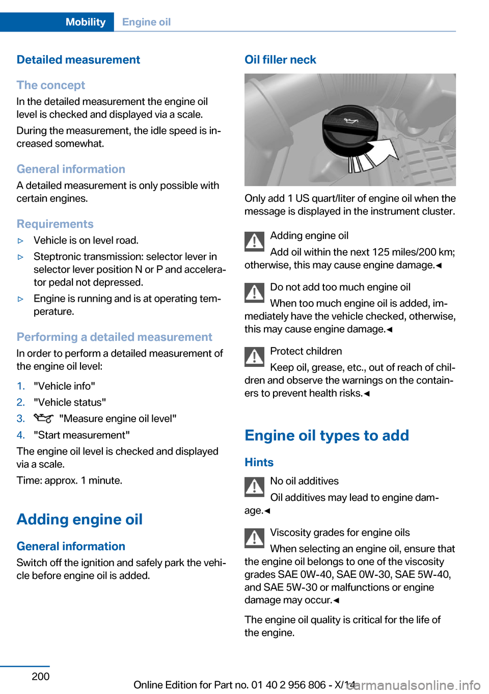
Oil filler neck
Only add 1 US quart/liter of engine oil when the
message is displayed in the instrument cluster.
Adding engine oil
Add oil within the next 125 miles/200 km;
otherwise, this may cause engine damage.◀
Do not add too much engine oil
When too much engine oil is added, im‐
mediately have the vehicle checked, otherwise,
this may cause engine damage.◀
Protect children
Keep oil, grease, etc., out of reach of chil‐
dren and observe the warnings on the contain‐
ers to prevent health risks.◀
Engine oil types to add Hints No oil additives
Oil additives may lead to engine dam‐
age.◀
Viscosity grades for engine oils
When selecting an engine oil, ensure that
the engine oil belongs to one of the viscosity
grades SAE 0W-40, SAE 0W-30, SAE 5W-40,
and SAE 5W-30 or malfunctions or engine
damage may occur.◀
The engine oil quality is critical for the life of
the engine.
Seite 200MobilityEngine oil200
Online Edition for Part no. 01 40 2 956 806 - X/14
Page 205 of 246
Approved engine oil types
You can add engine oils with the following
specifications:Gasoline engineBMW Longlife-01.BMW Longlife-01 FE.
Additional information about the approved
types of engine oils can be obtained from the
service center.
Alternative engine oil types If the approved engine oils are not available, up
to 1 US quart/liter of an engine oil with the fol‐
lowing specification can be added:
Gasoline engineAPI SM or superior grade specification.
Engine oil change:
The vehicle manufacturer recommends that
you let the service center change the motor oil.
Seite 201Engine oilMobility201
Online Edition for Part no. 01 40 2 956 806 - X/14
Page 213 of 246
Daytime running lights
24-watt bulb, PW24W.1.If necessary, remove the high beam bulb
connector.2.Remove the bulb holder.3.Remove the bulb from the bulb holder.4.To insert the new bulb, proceed in reverse
order of removal. During insertion, the bot‐
tom of the bulb holder must be facing
downward. Make sure that the bulb holder
snaps into place.5.Attach the high beam bulb connector.6.Close the headlight housing with the lid.
Make sure that the lid engages.
Xenon headlights
Xenon headlights
Because of the long life of these bulbs, the
likelihood of failure is very low. Switching the
lights on and off frequently shortens their life.
If a bulb fails, reel on the front fog lights and
continue the trip with great care. Comply with
local regulations.
Do not perform work/bulb replacement
on xenon headlights
Have any work on the xenon lighting system,
including bulb replacement, performed only by
a service center. Due to the high voltage
present in the system, there is a danger of fatal
injuries if work is carried out improperly.◀
For checking and adjusting headlamp aim,
please contact your BMW center.
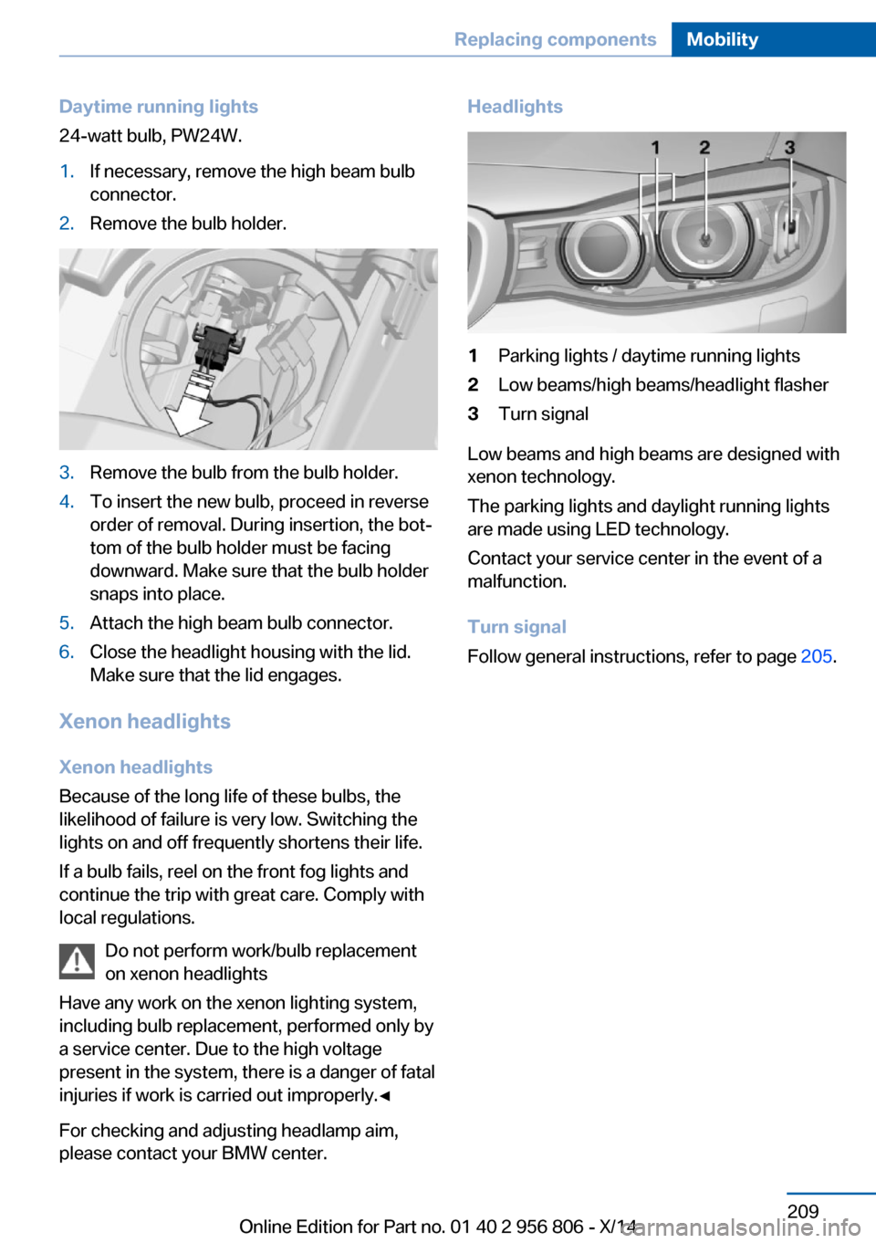
Headlights1Parking lights / daytime running lights2Low beams/high beams/headlight flasher3Turn signal
Low beams and high beams are designed with
xenon technology.
The parking lights and daylight running lights
are made using LED technology.
Contact your service center in the event of a
malfunction.
Turn signal
Follow general instructions, refer to page 205.
Seite 209Replacing componentsMobility209
Online Edition for Part no. 01 40 2 956 806 - X/14
Page 218 of 246
ter to ensure that all comfort features are fully
available and that any Check Control mes‐
sages of these comfort features are no longer
displayed.
Charging the battery
Note Do not connect charging devices to the
12 volt socket in the vehicle
Do not connect battery chargers to the fac‐
tory-installed 12 volt sockets in the vehicle as
this may damage the vehicle battery due to an
increased power consumption.◀
General information Make sure that the battery is always suffi‐
ciently charged to guarantee that the battery
remains usable for its full service life.
The battery may need to be charged in the fol‐
lowing cases:▷When making frequent short-distance
drives.▷If the vehicle is not used for prolonged pe‐
riods, longer than a month.
Starting aid terminals
In the vehicle, only charge the battery via the
starting aid terminals, refer to page 218, in the
engine compartment with the engine off.
Power failure After a temporary power loss, some equipment
needs to be newly initialized or individual set‐
tings updated, e.g.:
▷Seat and mirror memory: store the posi‐
tions again.▷Time: update.▷Date: update.▷Glass sunroof: initialize the system, refer to
page 49.Disposing of old batteries
Have old batteries disposed of by your
service center or bring them to a recy‐
cling center.
Maintain the battery in an upright position for
transport and storage. Secure the battery so
that it does not tip over during transport.
Fuses Hints Replacing fuses
Never attempt to repair a blown fuse and
do not replace a defective fuse with a substi‐
tute of another color or amperage rating; this
could lead to a circuit overload, ultimately re‐
sulting in a fire in the vehicle.◀
Plastic tweezers and information on the fuse
types and locations are stored in the fuse box
in the cargo area.
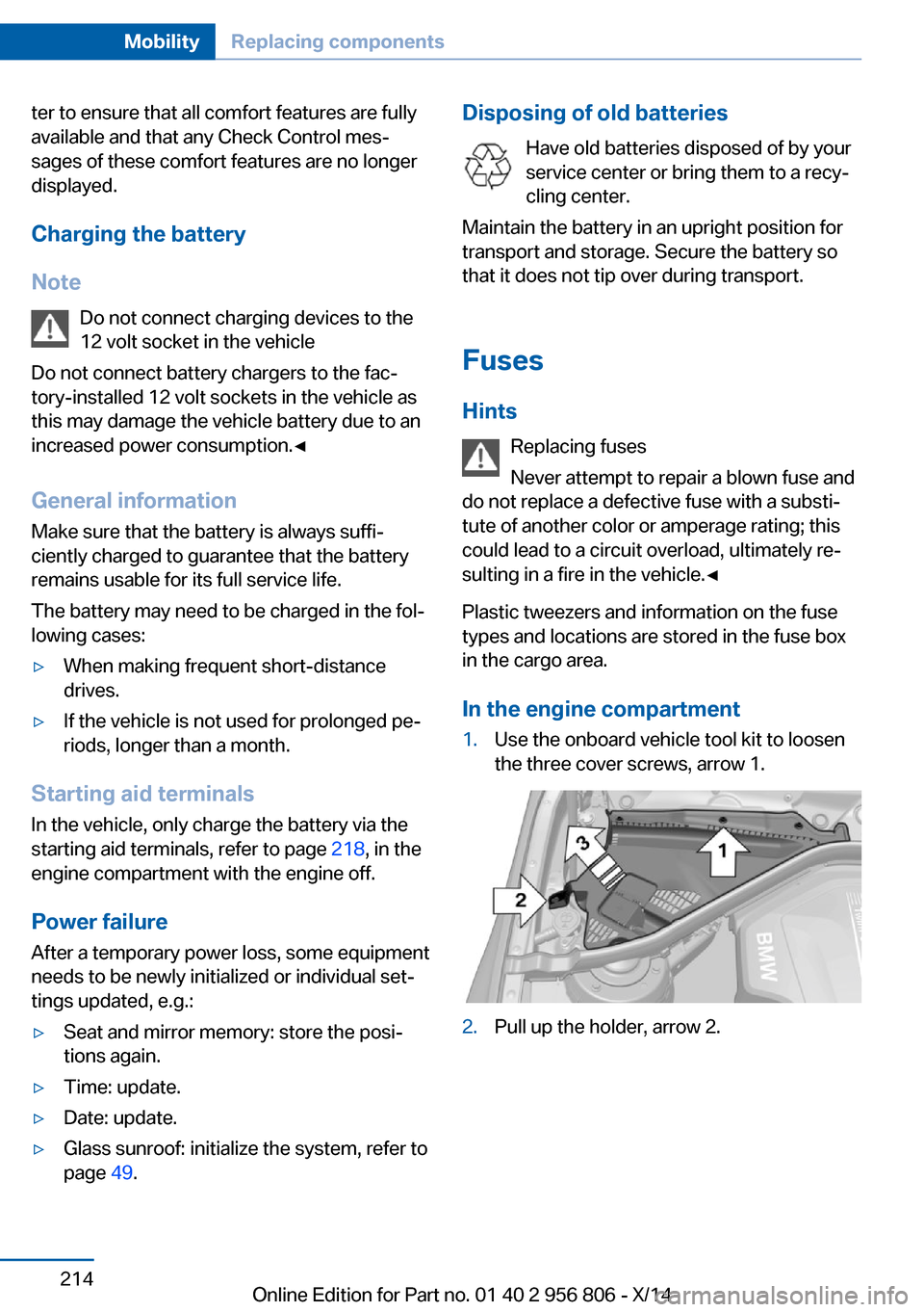
In the engine compartment1.Use the onboard vehicle tool kit to loosen
the three cover screws, arrow 1.2.Pull up the holder, arrow 2.Seite 214MobilityReplacing components214
Online Edition for Part no. 01 40 2 956 806 - X/14
Page 221 of 246
steps to help you under certain circum‐
stances.
For this, data are transmitted to the BMW
Response Center which serve to deter‐
mine the necessary rescue measures. E. g.
the current position of the vehicle, if it can
be established.▷If the LED is flashing green, but the BMW
Response Center can no longer be heard
via the speaker, you can nevertheless still
be heard at the BMW Response Center.
Initiating an Emergency Request
automatically
Under certain conditions, an Emergency Re‐
quest is automatically initiated immediately af‐
ter a severe accident. Automatic Collision Noti‐
fication is not affected by pressing the SOS
button.
Warning triangle
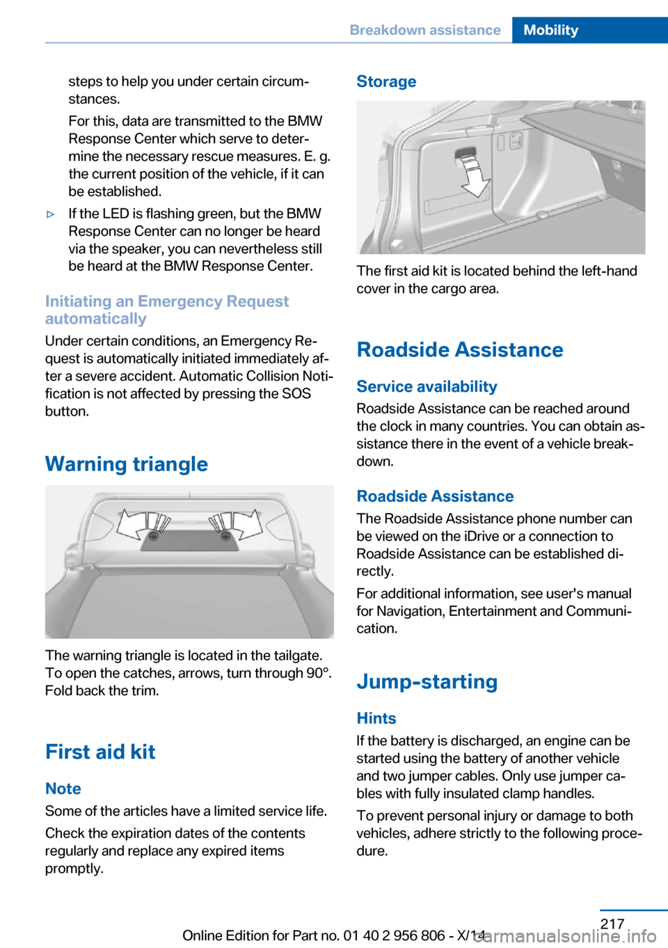
The warning triangle is located in the tailgate.
To open the catches, arrows, turn through 90°.
Fold back the trim.
First aid kit NoteSome of the articles have a limited service life.
Check the expiration dates of the contents
regularly and replace any expired items
promptly.
Storage
The first aid kit is located behind the left-hand
cover in the cargo area.
Roadside Assistance Service availability
Roadside Assistance can be reached around
the clock in many countries. You can obtain as‐
sistance there in the event of a vehicle break‐
down.
Roadside Assistance The Roadside Assistance phone number can
be viewed on the iDrive or a connection to
Roadside Assistance can be established di‐
rectly.
For additional information, see user's manual
for Navigation, Entertainment and Communi‐
cation.
Jump-starting
Hints
If the battery is discharged, an engine can be
started using the battery of another vehicle
and two jumper cables. Only use jumper ca‐
bles with fully insulated clamp handles.
To prevent personal injury or damage to both
vehicles, adhere strictly to the following proce‐
dure.
Seite 217Breakdown assistanceMobility217
Online Edition for Part no. 01 40 2 956 806 - X/14