div BMW 3 SERIES SEDAN 2013 F30 User Guide
[x] Cancel search | Manufacturer: BMW, Model Year: 2013, Model line: 3 SERIES SEDAN, Model: BMW 3 SERIES SEDAN 2013 F30Pages: 248, PDF Size: 5.21 MB
Page 106 of 248
MalfunctionThe yellow warning lamp flashes andthen lights up continuously. A Check
Control message is displayed. No flat
tire or loss of tire pressure can be detected.
Display in the following situations:▷A wheel without TPM electronics is fitted:
have the service center check it if neces‐
sary.▷Malfunction: have the system checked by
your service center.▷TPM was unable to complete the reset.
Reset the system again.▷Disturbance by systems or devices with
the same radio frequency: after leaving the
area of the disturbance, the system auto‐
matically becomes active again.
Declaration according to NHTSA/
FMVSS 138 Tire Pressure Monitoring
System
Each tire, including the spare (if provided)
should be checked monthly when cold and in‐
flated to the inflation pressure recommended
by the vehicle manufacturer on the vehicle
placard or tire inflation pressure label. (If your
vehicle has tires of a different size than the size
indicated on the vehicle placard or tire inflation
pressure label, you should determine the
proper tire inflation pressure for those tires.)
As an added safety feature, your vehicle has
been equipped with a tire pressure monitoring
system (TPMS) that illuminates a low tire pres‐
sure telltale when one or more of your tires is
significantly under-inflated. Accordingly, when
the low tire pressure telltale illuminates, you
should stop and check your tires as soon as
possible, and inflate them to the proper pres‐
sure. Driving on a significantly under-inflated
tire causes the tire to overheat and can lead to
tire failure. Under-inflation also reduces fuel ef‐
ficiency and tire tread life, and may affect the
vehicle's handling and stopping ability. Please
note that the TPMS is not a substitute for
proper tire maintenance, and it is the driver's
responsibility to maintain correct tire pressure,
even if under-inflation has not reached the
level to trigger illumination of the TPMS low
tire pressure telltale. Your vehicle has also
been equipped with a TPMS malfunction indi‐
cator to indicate when the system is not oper‐
ating properly. The TPMS malfunction indica‐
tor is combined with the low tire pressure
telltale. When the system detects a malfunc‐
tion, the telltale will flash for approximately one
minute and then remain continuously illumi‐
nated. This sequence will continue upon sub‐
sequent vehicle start-ups as long as the mal‐
function exists. When the malfunction indicator
is illuminated, the system may not be able to
detect or signal low tire pressure as intended.
TPMS malfunctions may occur for a variety of
reasons, including the installation of replace‐
ment or alternate tires or wheels on the vehicle
that prevent the TPMS from functioning prop‐
erly. Always check the TPMS malfunction tell‐
tale after replacing one or more tires or wheels
on your vehicle to ensure that the replacement
or alternate tires and wheels allow the TPMS
to continue to function properly.
FTM Flat Tire Monitor The conceptThe system detects a pressure loss on the ba‐sis of speed differences between the individual
wheels while driving.
In the event of a pressure loss, the diameter
and therefore the rotational speed of the corre‐
sponding wheel change. This is detected and
reported as a flat tire.
The system does not measure the actual infla‐
tion pressure in the tires.
Functional requirements
The system must have been initialized when
the tire inflation pressure was correct; other‐
wise, reliable signaling of a flat tire is not en‐Seite 102ControlsSafety102
Online Edition for Part no. 01 40 2 926 810 - X/13
Page 111 of 248
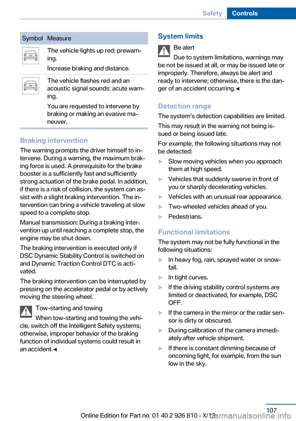
SymbolMeasureThe vehicle lights up red: prewarn‐
ing.
Increase braking and distance.The vehicle flashes red and an
acoustic signal sounds: acute warn‐
ing.
You are requested to intervene by
braking or making an evasive ma‐
neuver.
Braking intervention
The warning prompts the driver himself to in‐
tervene. During a warning, the maximum brak‐
ing force is used. A prerequisite for the brake
booster is a sufficiently fast and sufficiently
strong actuation of the brake pedal. In addition,
if there is a risk of collision, the system can as‐
sist with a slight braking intervention. The in‐ tervention can bring a vehicle traveling at slow
speed to a complete stop.
Manual transmission: During a braking inter‐
vention up until reaching a complete stop, the
engine may be shut down.
The braking intervention is executed only if
DSC Dynamic Stability Control is switched on
and Dynamic Traction Control DTC is acti‐
vated.
The braking intervention can be interrupted by
pressing on the accelerator pedal or by actively
moving the steering wheel.
Tow-starting and towing
When tow-starting and towing the vehi‐
cle, switch off the Intelligent Safety systems;
otherwise, improper behavior of the braking
function of individual systems could result in
an accident.◀
System limits
Be alert
Due to system limitations, warnings may
be not be issued at all, or may be issued late or
improperly. Therefore, always be alert and
ready to intervene; otherwise, there is the dan‐
ger of an accident occurring.◀
Detection range
The system's detection capabilities are limited.
This may result in the warning not being is‐
sued or being issued late.
For example, the following situations may not
be detected:▷Slow moving vehicles when you approach
them at high speed.▷Vehicles that suddenly swerve in front of
you or sharply decelerating vehicles.▷Vehicles with an unusual rear appearance.▷Two-wheeled vehicles ahead of you.▷Pedestrians.
Functional limitations
The system may not be fully functional in the
following situations:
▷In heavy fog, rain, sprayed water or snow‐
fall.▷In tight curves.▷If the driving stability control systems are
limited or deactivated, for example, DSC
OFF.▷If the camera in the mirror or the radar sen‐
sor is dirty or obscured.▷During calibration of the camera immedi‐
ately after vehicle shipment.▷If there is constant dimming because of
oncoming light, for example, from the sun
low in the sky.Seite 107SafetyControls107
Online Edition for Part no. 01 40 2 926 810 - X/13
Page 113 of 248
Switch the system back on: press the button
again.
Setting the warning time The warning time can be set via iDrive.1."Settings"2."Frontal Coll. Warning"3.Activate the desired warning time on the
Control Display.
The selected channel is stored for the remote
control currently in use.
Display
Warning stages
Prewarning
This warning is issued, for example, when
there is the impending danger of a collision or
the distance to the vehicle ahead is too small.
Acute warning with braking function
Warning of the imminent danger of a collision
when the vehicle approaches another object at
a relatively high differential speed.
The acute warning prompts the driver to inter‐
vene and, if there is the danger of a collision, is
accompanied by a braking intervention.
The braking intervention is executed with lim‐
ited braking force and for a brief period only.
The intervention can bring the vehicle to a
complete stop.
The braking intervention is executed only if
DSC Dynamic Stability Control is switched on
and Dynamic Traction Control DTC is acti‐
vated.
Above approx. 130 mph/210 km/h, the braking
intervention occurs as a brief braking pressure.
No automatic delay occurs.
Adapting your speed and driving style
The warning does not relieve the driver
of the responsibility to adapt his or her driving
speed and style to the traffic conditions.◀
The braking intervention can be interrupted by
pressing on the accelerator pedal or by actively
moving the steering wheel.
Tow-starting and towing
When tow-starting and towing the vehi‐
cle, switch off the Intelligent Safety systems;
otherwise, improper behavior of the braking
function of individual systems could result in
an accident.◀
Display in the instrument cluster The collision warning can be issued in the in‐
strument cluster, in the Head-up Display, and
acoustically.
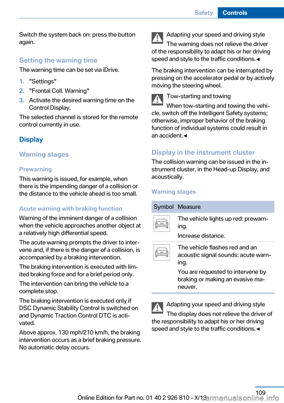
Warning stagesSymbolMeasureThe vehicle lights up red: prewarn‐
ing.
Increase distance.The vehicle flashes red and an
acoustic signal sounds: acute warn‐
ing.
You are requested to intervene by
braking or making an evasive ma‐
neuver.
Adapting your speed and driving style
The display does not relieve the driver of
the responsibility to adapt his or her driving
speed and style to the traffic conditions.◀
Seite 109SafetyControls109
Online Edition for Part no. 01 40 2 926 810 - X/13
Page 114 of 248
System limitsBe alert
Due to system limitations, warnings may
be not be issued at all, or may be issued late or
improperly. Therefore, always be alert and
ready to intervene; otherwise, there is the dan‐
ger of an accident occurring.◀
Detection range
The system's detection capabilities are limited.
This may result in the warning not being is‐
sued or being issued late.
For example, the following situations may not
be detected:▷Slow moving vehicles when you approach
them at high speed.▷Vehicles that suddenly swerve in front of
you or sharply decelerating vehicles.▷Vehicles with an unusual rear appearance.▷Two-wheeled vehicles ahead of you.▷Pedestrians.
Functional limitations
The system may not be fully functional in the
following situations:
▷In heavy fog, rain, sprayed water or snow‐
fall.▷In tight curves.▷If the driving stability control systems are
limited or deactivated, for example, DSC
OFF.▷If the camera in the mirror or the radar sen‐
sor is dirty or obscured.▷During calibration of the camera immedi‐
ately after vehicle shipment.▷If there is constant dimming because of
oncoming light, for example, from the sun
low in the sky.Prewarning sensitivity
Depending on the set prewarning time, this
may result in increased false warnings.
Pedestrian warning with citybraking function
The concept
The system can help to prevent accidents with
pedestrians.
The system issues a warning in the city driving
speed area if there is imminent danger of a col‐
lision with pedestrians and includes a braking
function.
The system is controlled via the camera in the
base of the interior mirror.
General information The system issues a warning with brightness
staring at approx. 6 mph/10 km/h to approx.
35 mph/60 km/h regarding a possible risk of
collision with pedestrians and assists with a
brake intervention shortly before a collision.
It responds to persons that are within the de‐
tection range of the system.
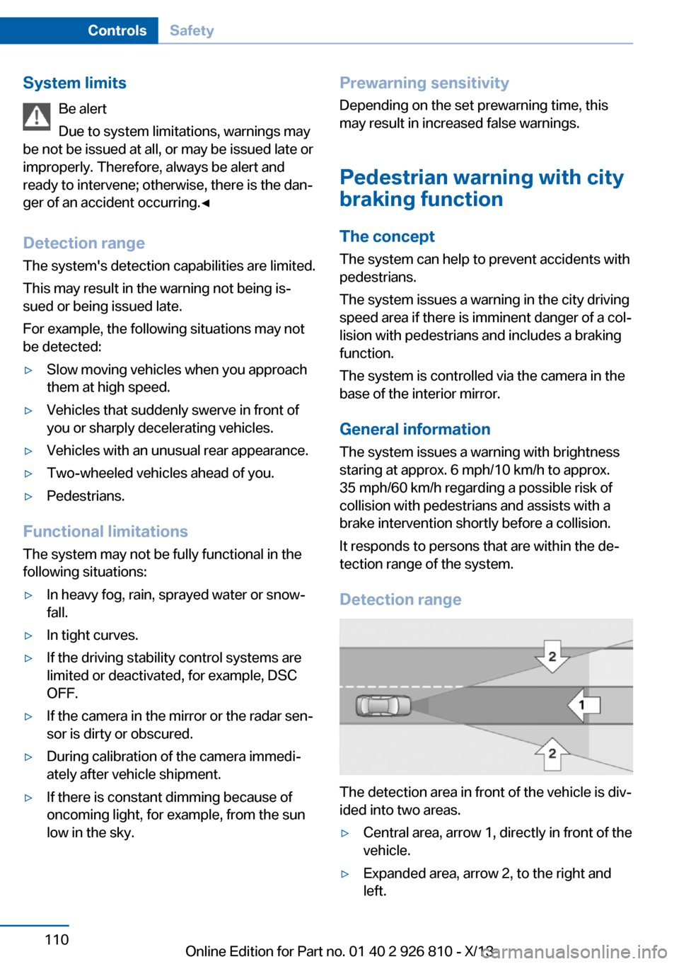
Detection range
The detection area in front of the vehicle is div‐
ided into two areas.
▷Central area, arrow 1, directly in front of the
vehicle.▷Expanded area, arrow 2, to the right and
left.Seite 110ControlsSafety110
Online Edition for Part no. 01 40 2 926 810 - X/13
Page 116 of 248
The braking intervention can be interrupted by
pressing on the accelerator pedal or by actively
moving the steering wheel.
Tow-starting and towing
When tow-starting and towing the vehi‐
cle, switch off the Intelligent Safety systems;
otherwise, improper behavior of the braking
function of individual systems could result in
an accident.◀
System limits Be alert
Due to system limitations, warnings may
be not be issued at all, or may be issued late or
improperly. Therefore, always be alert and
ready to intervene; otherwise, there is the dan‐
ger of an accident occurring.◀
Detection range
The detection capability of the camera is lim‐
ited.
This may result in the warning not being is‐
sued or being issued late.
For example, the following situations may not
be detected:▷Partially covered pedestrians.▷Pedestrians that are not detected as such
because of the viewing angle or contour.▷Pedestrians outside of the detection range.▷Pedestrians having a body size less than
32 in/80 cm.
Functional limitations
The system may not be fully functional or may
not be available in the following situations:
▷In heavy fog, rain, sprayed water or snow‐
fall.▷In tight curves.▷If the camera view field or the front wind‐
shield are dirty or covered.▷When driving toward bright lights.▷Up to 10 seconds after the start of the en‐
gine, via the Start/Stop knob.▷During calibration of the camera immedi‐
ately after vehicle shipment.▷When it is dark outside.
Lane departure warning
The concept Starting at a specific speed, this system alerts
you when the vehicle on streets with lane
markings is about to leave the lane. This
speed, depending on the country version, is
between 35 mph/55 km/h and
45 mph/70 km/h.
When switching on the system below this
speed, a message is displayed in the instru‐
ment cluster.
The steering wheel begins vibrating gently in
the event of warnings. The time of the warning
may vary depending on the current driving sit‐
uation.
The system does not provide a warning if the
turn signal is set before leaving the lane.
Notes Personal responsibility
The system cannot serve as a substitute
for the driver's personal judgment of the
course of the road and the traffic situation.
In the event of a warning, do not jerk the steer‐
ing wheel, as you may lose control of the vehi‐
cle.◀
Seite 112ControlsSafety112
Online Edition for Part no. 01 40 2 926 810 - X/13
Page 117 of 248
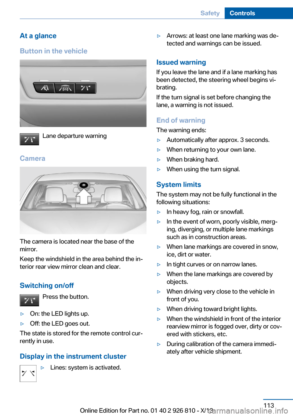
At a glance
Button in the vehicle
Lane departure warning
Camera
The camera is located near the base of the
mirror.
Keep the windshield in the area behind the in‐
terior rear view mirror clean and clear.
Switching on/off Press the button.
▷On: the LED lights up.▷Off: the LED goes out.
The state is stored for the remote control cur‐
rently in use.
Display in the instrument cluster
▷Lines: system is activated.▷Arrows: at least one lane marking was de‐
tected and warnings can be issued.
Issued warning
If you leave the lane and if a lane marking has
been detected, the steering wheel begins vi‐
brating.
If the turn signal is set before changing the
lane, a warning is not issued.
End of warning
The warning ends:
▷Automatically after approx. 3 seconds.▷When returning to your own lane.▷When braking hard.▷When using the turn signal.
System limits
The system may not be fully functional in the
following situations:
▷In heavy fog, rain or snowfall.▷In the event of worn, poorly visible, merg‐
ing, diverging, or multiple lane markings
such as in construction areas.▷When lane markings are covered in snow,
ice, dirt or water.▷In tight curves or on narrow lanes.▷When the lane markings are covered by
objects.▷When driving very close to the vehicle in
front of you.▷When driving toward bright lights.▷When the windshield in front of the interior
rearview mirror is fogged over, dirty or cov‐
ered with stickers, etc.▷During calibration of the camera immedi‐
ately after vehicle shipment.Seite 113SafetyControls113
Online Edition for Part no. 01 40 2 926 810 - X/13
Page 120 of 248
Driving stability control systemsVehicle equipmentAll standard, country-specific and optional
equipment that is offered in the model series is
described in this chapter. Therefore, equip‐
ment is also described that is not available in a
vehicle, e. g., because of the selected optional
equipment or country variant. This also applies
for safety-related functions and systems.
Antilock Brake System ABS ABS prevents locking of the wheels during
braking.
The vehicle remains steerable even during full
brake applications, thus increasing active
safety.
ABS is operational every time you start the en‐
gine.
Brake assistant
When you apply the brakes rapidly, this system
automatically produces the maximum braking
force boost. This then reduces braking dis‐ tance to a minimum during full braking. This
system utilizes all of the benefits provided by ABS.
Do not reduce the pressure on the brake pedal
for the duration of the full braking.
DSC Dynamic Stability
Control
The concept
DSC prevents traction loss in the driving
wheels when driving away and accelerating.
DSC also recognizes unstable vehicle condi‐
tions, such as fishtailing or nose-diving. Sub‐ject to physical limits, DSC helps to keep the
vehicle on a steady course by reducing engine
speed and by applying brakes to the individual
wheels.
Adjust your driving style to the situation
An appropriate driving style is always the
responsibility of the driver.
The laws of physics cannot be repealed, even
with DSC.
Therefore, do not reduce the additional safety
margin by driving in a risky manner.◀
Indicator/warning lamps The indicator lamp flashes: DSC con‐
trols the drive forces and brake forces.
The indicator lamp lights up: DSC has
failed.
Deactivating DSC: DSC OFF
When DSC is deactivated, driving stability is
reduced during acceleration and when driving
in bends.
To increase vehicle stability, activate DSC
again as soon as possible.
Deactivating DSC Press and hold the button, but not lon‐
ger than approx. 10 seconds, until the
indicator lamp for DSC OFF lights up in the in‐
strument cluster and DSC OFF is displayed.
The DSC system is switched off.
Activating DSC Press the button.
DSC OFF and the DSC OFF indicator
lamp go out.Seite 116ControlsDriving stability control systems116
Online Edition for Part no. 01 40 2 926 810 - X/13
Page 123 of 248
The program can be configured to individual
specifications. The configuration is stored for
the remote control currently in use.
Activating SPORT Press button repeatedly until SPORT
is displayed in the instrument cluster.
Configuring SPORT When the display is activated on the Control
Display, refer to page 119, the SPORT driving
mode can be set to individual specifications.▷Activating SPORT.▷"Configure SPORT"▷Configuring the SPORT driving mode.
SPORT can also be configured before it is acti‐
vated:
1."Settings"2."Driving mode"3."Configure SPORT"4.Configure driving mode.
This configuration is retrieved when the
SPORT driving mode is activated.
COMFORT For a balanced tuning with maximum driving
stabilization.
Activating COMFORT Press button repeatedly until COM‐
FORT is displayed in the instrument
cluster.
In certain situations, the system automatically
changes to the NORMAL program, automatic
program change, refer to page 118.
ECO PRO ECO PRO, refer to page 173, provides consis‐
tent tuning to minimize fuel consumption for
maximum range with maximum driving stabili‐
zation.
Comfort functions and the engine controller
are adjusted.
The program can be configured to individual
specifications.
Activating ECO PRO Press button repeatedly until ECO
PRO is displayed in the instrument
cluster.
Configuring ECO PRO1.Activate ECO PRO.2."Configure ECO PRO"
Make the desired settings.
Configuring drive program
Settings can be made for the following driving
programs in Driving mode:
▷SPORT, refer to page 119.▷ECO PRO, refer to page 174.
Displays
Program selection Pressing the button displays a
list of the selectable programs.
Selected program The selected program is dis‐
played in the instrument cluster.
Display on the Control Display
Program changes can be displayed on the
Control Display.
1."Settings"Seite 119Driving stability control systemsControls119
Online Edition for Part no. 01 40 2 926 810 - X/13
Page 156 of 248
rearview mirror. The required distance de‐
pends on the manual transmitter.4.Simultaneously press and hold the button
of the desired function on the hand-held
transmitter and the button to be program‐
med on the interior rearview mirror. The
LED on the interior rearview mirror will be‐
gin flashing slowly.5.Release both buttons as soon as the LED
flashes more rapidly. When the LED is
flashing faster, this indicates that the but‐
ton on the interior rearview mirror has been
programmed.
If the LED does not flash faster after at
least 60 seconds, change the distance be‐
tween the interior rearview mirror and the
hand-held transmitter and repeat the step.
Several more attempts at different distan‐
ces may be necessary. Wait at least
15 seconds between attempts.
Canada: if programming with the hand-
held transmitter was interrupted, hold
down the interior rearview mirror button
and repeatedly press and release the
hand-held transmitter button for 2 sec‐
onds.6.To program other functions on other but‐
tons, repeat steps 3 to 5.
The systems can be controlled using the inte‐
rior rearview mirror buttons.
Special feature of the alternating-
code wireless system
If you are unable to operate the system after
repeated programming, please check if the
system to be controlled features an alternat‐
ing-code system.
Read the system's operating manual, or press
the programmed button on the interior rear‐
view mirror longer. If the LED on the interior
rearview mirror starts flashing rapidly and then
stays lit constantly for 2 seconds, the system
features an alternating-code system. Flashing
and continuous illumination of the LED will re‐
peat for approximately 20 seconds.
For systems with an alternating-code system,
the universal garage door opener and the sys‐
tem also have to be synchronized.
Please read the operating manual of the sys‐
tem being set up for information on how to
synchronize the system.
Synchronizing is easier with the aid of a sec‐
ond person.
To synchronize:1.Park the vehicle within range of the re‐
mote-controlled system.2.Program the relevant button on the interior
rearview mirror as described.3.Locate and press the synchronizing button
on the system being programmed. You
have approx. 30 seconds for the next step.4.Hold down the programmed button on the
interior rearview mirror for approximately
3 seconds and then release it. If necessary,
repeat this work step up to three times in
order to finish synchronization. Once syn‐
chronization is complete, the programmed
function will be carried out.
Reprogramming individual buttons
1.Switch on the ignition.2.Press and hold the interior rearview mirror
button to be programmed.3.As soon as the interior rearview mirror LED
starts flashing slowly, hold the hand-held
transmitter for the system to be controlled
approx. 1 to 3 in/2.5 to 8 cm away from the
buttons on the interior rearview mirror. The
required distance depends on the manual
transmitter.4.Likewise, press and hold the button of the
desired function on the hand-held trans‐
mitter.5.Release both buttons as soon as the inte‐
rior rearview mirror LED flashes more rap‐
idly. When the LED is flashing faster, thisSeite 152ControlsInterior equipment152
Online Edition for Part no. 01 40 2 926 810 - X/13
Page 157 of 248
indicates that the button on the interior
rearview mirror has been programmed.
The system can then be controlled by the
button on the interior rearview mirror.
If the LED does not flash faster after at
least 60 seconds, change the distance and
repeat the step. Several more attempts at
different distances may be necessary. Wait
at least 15 seconds between attempts.
Canada: if programming with the hand-
held transmitter was interrupted, hold
down the interior rearview mirror button
and repeatedly press and release the
hand-held transmitter button for 2 sec‐
onds.
Controls
Before operation
Before operating a system using the
integrated universal remote control, ensure
that there are no people, animals, or objects
within the range of movement of the remote- controlled system; otherwise, there is a risk of
injury or damage.
Also follow the safety instructions of the hand-
held transmitter.◀
The system, such as the garage door, can be
operated using the button on the interior rear‐
view mirror while the engine is running or when
the ignition is started. To do this, hold down
the button within receiving range of the system
until the function is activated. The interior rear‐ view mirror LED stays lit while the wireless sig‐
nal is being transmitted.
Deleting stored functions Press and hold the left and right button on the
interior rearview mirror simultaneously for ap‐
proximately 20 seconds until the LED flashes
rapidly. All stored functions are deleted. The
functions cannot be deleted individually.
Digital compass
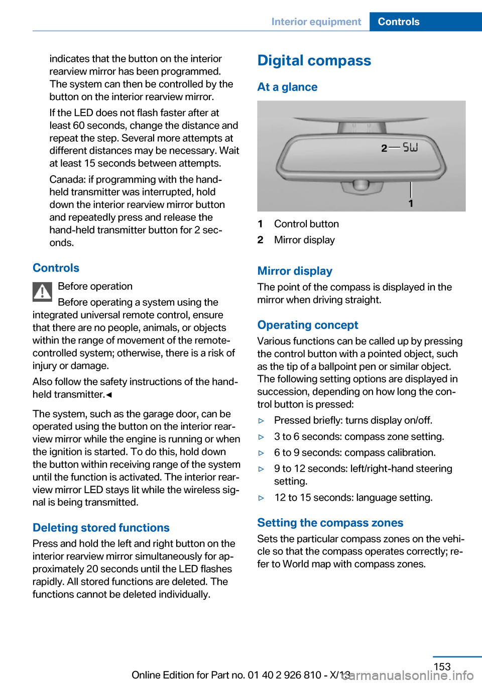
At a glance1Control button2Mirror display
Mirror display
The point of the compass is displayed in the
mirror when driving straight.
Operating concept
Various functions can be called up by pressing
the control button with a pointed object, such
as the tip of a ballpoint pen or similar object.
The following setting options are displayed in
succession, depending on how long the con‐
trol button is pressed:
▷Pressed briefly: turns display on/off.▷3 to 6 seconds: compass zone setting.▷6 to 9 seconds: compass calibration.▷9 to 12 seconds: left/right-hand steering
setting.▷12 to 15 seconds: language setting.
Setting the compass zones
Sets the particular compass zones on the vehi‐
cle so that the compass operates correctly; re‐
fer to World map with compass zones.
Seite 153Interior equipmentControls153
Online Edition for Part no. 01 40 2 926 810 - X/13