Malfunction BMW 3 SERIES SEDAN 2013 F30 Owner's Manual
[x] Cancel search | Manufacturer: BMW, Model Year: 2013, Model line: 3 SERIES SEDAN, Model: BMW 3 SERIES SEDAN 2013 F30Pages: 248, PDF Size: 5.21 MB
Page 12 of 248
chemicals known to the State of California to
cause cancer and birth defects or other repro‐
ductive harm. Battery posts, terminals and re‐
lated accessories contain lead and lead com‐
pounds. Wash your hands after handling. Used
engine oil contains chemicals that have caused
cancer in laboratory animals. Always protect
your skin by washing thoroughly with soap and
water.
Service and warranty
We recommend that you read this publication
thoroughly. Your vehicle is covered by the fol‐
lowing warranties:▷New Vehicle Limited Warranty.▷Rust Perforation Limited Warranty.▷Federal Emissions System Defect War‐
ranty.▷Federal Emissions Performance Warranty.▷California Emission Control System Lim‐
ited Warranty.
Detailed information about these warranties is
listed in the Service and Warranty Information
Booklet for US models or in the Warranty and
Service Guide Booklet for Canadian models.
Your vehicle has been specifically adapted and
designed to meet the particular operating con‐
ditions and homologation requirements in your
country and continental region in order to de‐
liver the full driving pleasure while the vehicle
is operated under those conditions. If you wish
to operate your vehicle in another country or
region, you may be required to adapt your ve‐
hicle to meet different prevailing operating
conditions and homologation requirements.
You should also be aware of any applicable
warranty limitations or exclusions for such
country or region. In such case, please contact
Customer Relations for further information.
Maintenance
Maintain the vehicle regularly to sustain the
road safety, operational reliability and the New
Vehicle Limited Warranty.
Specifications for required maintenance meas‐
ures:▷BMW Maintenance system▷Service and Warranty Information Booklet
for US models▷Warranty and Service Guide Booklet for
Canadian models
If the vehicle is not maintained according to
these specifications, this could result in seri‐
ous damage to the vehicle. Such damage is
not covered by the BMW New Vehicle Limited
Warranty.
Data memory
Many electronic components on your vehicle
are equipped with data memories that tempo‐
rarily or permanently store technical informa‐
tion about the condition of the vehicle, events
and faults. This technical information generally
documents the state of a component, a mod‐ ule, a system or the environment:
▷Operating states of system components,
fill levels for instance.▷Status messages for the vehicle and from
its individual components, e.g., wheel rota‐
tion speed/ vehicle speed, deceleration,
transverse acceleration.▷Malfunctions and faults in important sys‐
tem components, e.g., lights and brakes.▷Responses by the vehicle to special situa‐
tions, e.g., deployment of an airbag, en‐
gagement of stability control systems.▷Ambient conditions, such as temperature.
This data is purely technical in nature and is
used to detect and correct faults and to opti‐
mize vehicle functions. Motion profiles over
routes traveled cannot be created from this
data. When service offerings are used, e.g., re‐
pair services, service processes, warranty
claims, quality assurance, this technical infor‐
mation can be read out from the event and
fault memories by the service personnel, in‐
Seite 8Notes8
Online Edition for Part no. 01 40 2 926 810 - X/13
Page 43 of 248
Malfunction
If the vehicle can no longer be locked or un‐
locked with the remote control, the battery
may be discharged or there may be interfer‐
ence from external sources such as mobile
phones, metal objects, overhead power lines,
transmission towers, etc.
If this occurs, lock or unlock the driver's door at
the door lock using the integrated key.
For US owners only
The transmitter and receiver units comply with
part 15 of the FCC/Federal Communication
Commission regulations. Operation is gov‐
erned by the following:
FCC ID:▷LX8766S.▷LX8766E.▷LX8CAS.▷LX8CAS2.▷MYTCAS4.
Compliance statement:
This device complies with part 15 of the FCC
Rules. Operation is subject to the following
two conditions:
▷This device may not cause harmful inter‐
ference, and▷this device must accept any interference
received, including interference that may
cause undesired operation.
Any unauthorized modifications or changes to
these devices could void the user's authority to
operate this equipment.
Using the door lock
General information
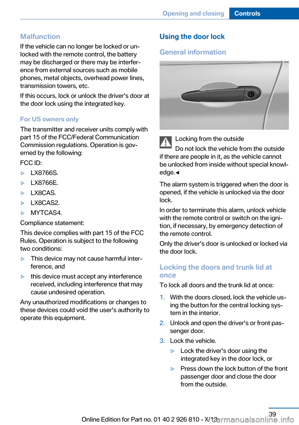
Locking from the outside
Do not lock the vehicle from the outside
if there are people in it, as the vehicle cannot
be unlocked from inside without special knowl‐
edge.◀
The alarm system is triggered when the door is
opened, if the vehicle is unlocked via the door
lock.
In order to terminate this alarm, unlock vehicle
with the remote control or switch on the igni‐
tion, if necessary, by emergency detection of
the remote control.
Only the driver's door is unlocked or locked via
the door lock.
Locking the doors and trunk lid atonce
To lock all doors and the trunk lid at once:
1.With the doors closed, lock the vehicle us‐
ing the button for the central locking sys‐
tem in the interior.2.Unlock and open the driver's or front pas‐
senger door.3.Lock the vehicle.▷Lock the driver's door using the
integrated key in the door lock, or▷Press down the lock button of the front
passenger door and close the door
from the outside.Seite 39Opening and closingControls39
Online Edition for Part no. 01 40 2 926 810 - X/13
Page 44 of 248
The fuel filler flap can only be locked using the
remote control.
Manual operation If an electrical malfunction occurs, lock or un‐
lock the vehicle using the integrated key via
the door lock on the driver's door.
Opening and closing: from
the inside
Locking and unlocking
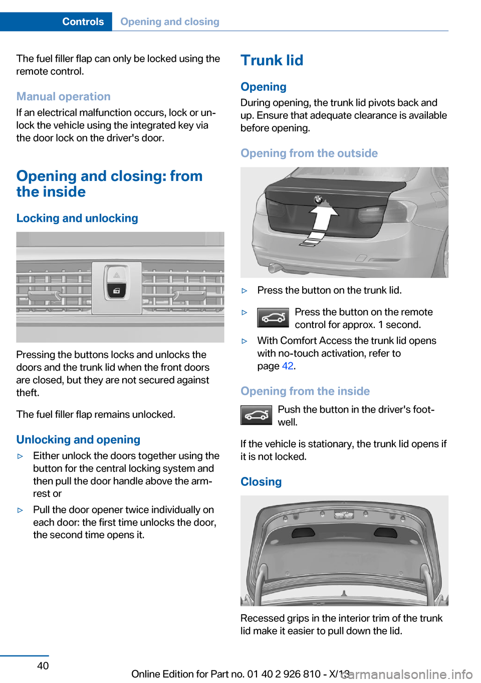
Pressing the buttons locks and unlocks the
doors and the trunk lid when the front doors
are closed, but they are not secured against
theft.
The fuel filler flap remains unlocked.
Unlocking and opening
▷Either unlock the doors together using the
button for the central locking system and
then pull the door handle above the arm‐
rest or▷Pull the door opener twice individually on
each door: the first time unlocks the door,
the second time opens it.Trunk lid
Opening
During opening, the trunk lid pivots back and
up. Ensure that adequate clearance is available
before opening.
Opening from the outside▷Press the button on the trunk lid.▷Press the button on the remote
control for approx. 1 second.▷With Comfort Access the trunk lid opens
with no-touch activation, refer to
page 42.
Opening from the inside
Push the button in the driver's foot‐
well.
If the vehicle is stationary, the trunk lid opens if
it is not locked.
Closing
Recessed grips in the interior trim of the trunk
lid make it easier to pull down the lid.
Seite 40ControlsOpening and closing40
Online Edition for Part no. 01 40 2 926 810 - X/13
Page 47 of 248
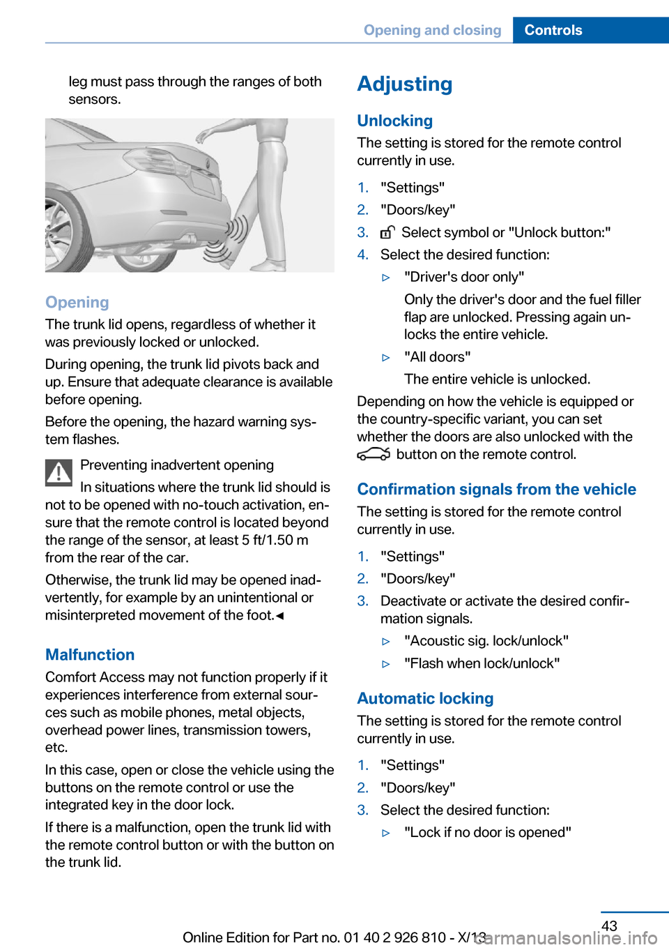
leg must pass through the ranges of both
sensors.
Opening
The trunk lid opens, regardless of whether it
was previously locked or unlocked.
During opening, the trunk lid pivots back and
up. Ensure that adequate clearance is available
before opening.
Before the opening, the hazard warning sys‐
tem flashes.
Preventing inadvertent opening
In situations where the trunk lid should is
not to be opened with no-touch activation, en‐
sure that the remote control is located beyond
the range of the sensor, at least 5 ft/1.50 m
from the rear of the car.
Otherwise, the trunk lid may be opened inad‐
vertently, for example by an unintentional or
misinterpreted movement of the foot.◀
Malfunction
Comfort Access may not function properly if it
experiences interference from external sour‐
ces such as mobile phones, metal objects,
overhead power lines, transmission towers,
etc.
In this case, open or close the vehicle using the
buttons on the remote control or use the
integrated key in the door lock.
If there is a malfunction, open the trunk lid with
the remote control button or with the button on
the trunk lid.
Adjusting
Unlocking The setting is stored for the remote control
currently in use.1."Settings"2."Doors/key"3. Select symbol or "Unlock button:"4.Select the desired function:▷"Driver's door only"
Only the driver's door and the fuel filler
flap are unlocked. Pressing again un‐
locks the entire vehicle.▷"All doors"
The entire vehicle is unlocked.
Depending on how the vehicle is equipped or
the country-specific variant, you can set
whether the doors are also unlocked with the
button on the remote control.
Confirmation signals from the vehicle
The setting is stored for the remote control
currently in use.
1."Settings"2."Doors/key"3.Deactivate or activate the desired confir‐
mation signals.▷"Acoustic sig. lock/unlock"▷"Flash when lock/unlock"
Automatic locking
The setting is stored for the remote control
currently in use.
1."Settings"2."Doors/key"3.Select the desired function:▷"Lock if no door is opened"Seite 43Opening and closingControls43
Online Edition for Part no. 01 40 2 926 810 - X/13
Page 61 of 248
Depending on how the vehicle is equipped, the
mirror setting is stored for the remote control
in use. When the vehicle is unlocked via the re‐
mote control, the position is automatically re‐
trieved if the setting for this function is active.
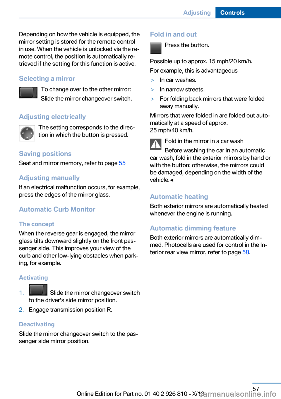
Selecting a mirror To change over to the other mirror:Slide the mirror changeover switch.
Adjusting electrically The setting corresponds to the direc‐
tion in which the button is pressed.
Saving positions Seat and mirror memory, refer to page 55
Adjusting manually If an electrical malfunction occurs, for example,
press the edges of the mirror glass.
Automatic Curb Monitor
The concept
When the reverse gear is engaged, the mirror
glass tilts downward slightly on the front pas‐
senger side. This improves your view of the
curb and other low-lying obstacles when park‐
ing, for example.
Activating1. Slide the mirror changeover switch
to the driver's side mirror position.2.Engage transmission position R.
Deactivating
Slide the mirror changeover switch to the pas‐
senger side mirror position.
Fold in and out
Press the button.
Possible up to approx. 15 mph/20 km/h.
For example, this is advantageous▷In car washes.▷In narrow streets.▷For folding back mirrors that were folded
away manually.
Mirrors that were folded in are folded out auto‐
matically at a speed of approx.
25 mph/40 km/h.
Fold in the mirror in a car wash
Before washing the car in an automatic
car wash, fold in the exterior mirrors by hand or
with the button; otherwise, the mirrors could
be damaged, depending on the width of the
vehicle.◀
Automatic heating
Both exterior mirrors are automatically heated
whenever the engine is running.
Automatic dimming feature Both exterior mirrors are automatically dim‐
med. Photocells are used for control in the In‐
terior rear view mirror, refer to page 58.
Seite 57AdjustingControls57
Online Edition for Part no. 01 40 2 926 810 - X/13
Page 71 of 248
Activating/deactivating the system
manually
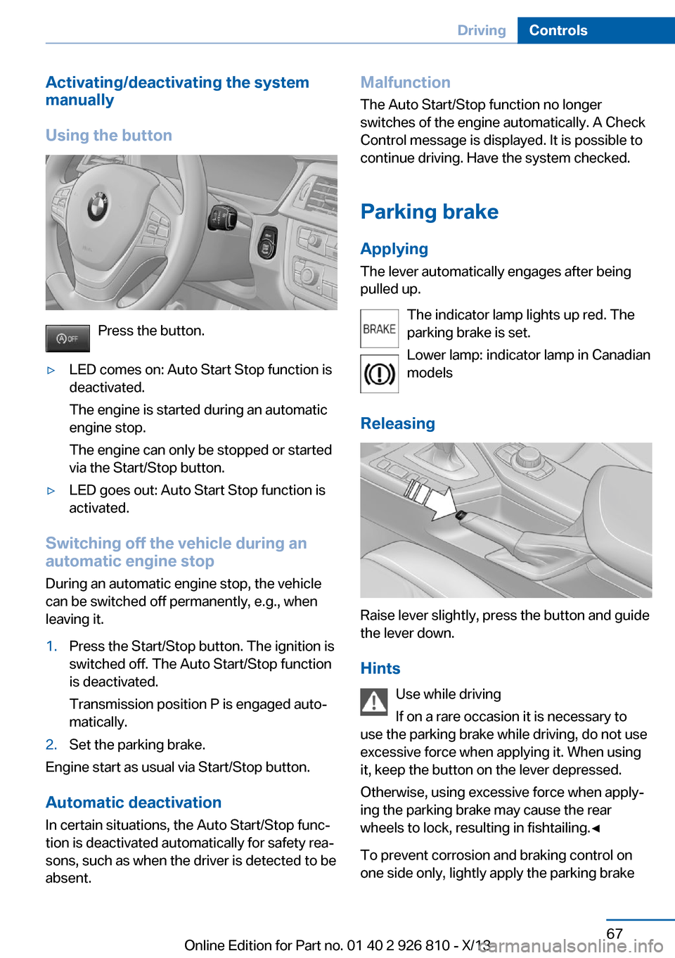
Using the button
Press the button.
▷LED comes on: Auto Start Stop function is
deactivated.
The engine is started during an automatic
engine stop.
The engine can only be stopped or started
via the Start/Stop button.▷LED goes out: Auto Start Stop function is
activated.
Switching off the vehicle during an
automatic engine stop
During an automatic engine stop, the vehicle
can be switched off permanently, e.g., when
leaving it.
1.Press the Start/Stop button. The ignition is
switched off. The Auto Start/Stop function
is deactivated.
Transmission position P is engaged auto‐
matically.2.Set the parking brake.
Engine start as usual via Start/Stop button.
Automatic deactivation
In certain situations, the Auto Start/Stop func‐
tion is deactivated automatically for safety rea‐
sons, such as when the driver is detected to be
absent.
Malfunction
The Auto Start/Stop function no longer
switches of the engine automatically. A Check
Control message is displayed. It is possible to
continue driving. Have the system checked.
Parking brake Applying
The lever automatically engages after being
pulled up.
The indicator lamp lights up red. The
parking brake is set.
Lower lamp: indicator lamp in Canadian
models
Releasing
Raise lever slightly, press the button and guide
the lever down.
Hints Use while driving
If on a rare occasion it is necessary to
use the parking brake while driving, do not use
excessive force when applying it. When using
it, keep the button on the lever depressed.
Otherwise, using excessive force when apply‐
ing the parking brake may cause the rear
wheels to lock, resulting in fishtailing.◀
To prevent corrosion and braking control on
one side only, lightly apply the parking brake
Seite 67DrivingControls67
Online Edition for Part no. 01 40 2 926 810 - X/13
Page 82 of 248
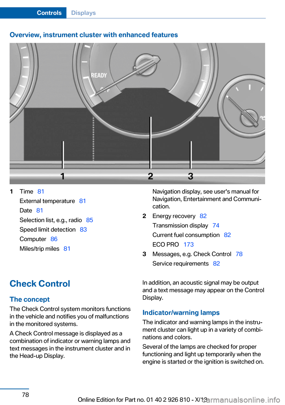
Overview, instrument cluster with enhanced features1Time 81
External temperature 81
Date 81
Selection list, e.g., radio 85
Speed limit detection 83
Computer 86
Miles/trip miles 81Navigation display, see user's manual for
Navigation, Entertainment and Communi‐
cation.2Energy recovery 82
Transmission display 74
Current fuel consumption 82
ECO PRO 1733Messages, e.g. Check Control 78
Service requirements 82Check Control
The concept The Check Control system monitors functions
in the vehicle and notifies you of malfunctions
in the monitored systems.
A Check Control message is displayed as a
combination of indicator or warning lamps and
text messages in the instrument cluster and in
the Head-up Display.In addition, an acoustic signal may be output
and a text message may appear on the Control Display.
Indicator/warning lamps The indicator and warning lamps in the instru‐
ment cluster can light up in a variety of combi‐
nations and colors.
Several of the lamps are checked for proper
functioning and light up temporarily when the
engine is started or the ignition is switched on.Seite 78ControlsDisplays78
Online Edition for Part no. 01 40 2 926 810 - X/13
Page 84 of 248
Symbols
Depending on the Check Control message, the
following functions can be selected.▷ "Owner's Manual"
Display additional information about the
Check Control message in the Integrated
Owner's Manual.▷ "Service request"
Contact your service center.▷ "Roadside Assistance"
Contact Roadside Assistance.
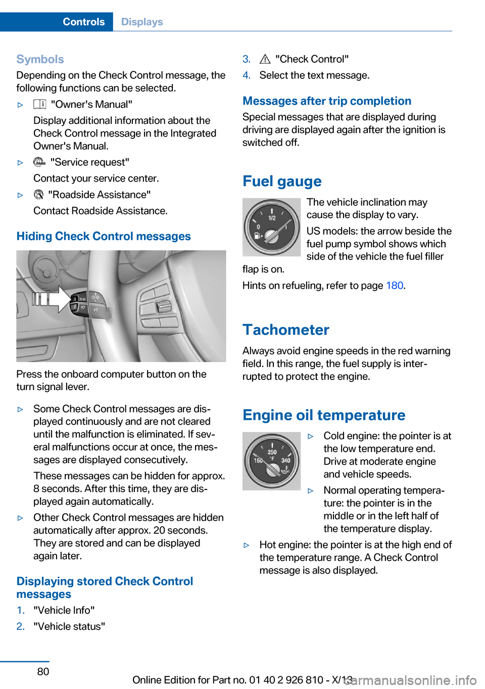
Hiding Check Control messages
Press the onboard computer button on the
turn signal lever.
▷Some Check Control messages are dis‐
played continuously and are not cleared
until the malfunction is eliminated. If sev‐
eral malfunctions occur at once, the mes‐
sages are displayed consecutively.
These messages can be hidden for approx.
8 seconds. After this time, they are dis‐
played again automatically.▷Other Check Control messages are hidden
automatically after approx. 20 seconds.
They are stored and can be displayed
again later.
Displaying stored Check Control
messages
1."Vehicle Info"2."Vehicle status"3. "Check Control"4.Select the text message.
Messages after trip completion
Special messages that are displayed during
driving are displayed again after the ignition is
switched off.
Fuel gauge The vehicle inclination may
cause the display to vary.
US models: the arrow beside the
fuel pump symbol shows which
side of the vehicle the fuel filler
flap is on.
Hints on refueling, refer to page 180.
Tachometer
Always avoid engine speeds in the red warning
field. In this range, the fuel supply is inter‐
rupted to protect the engine.
Engine oil temperature
▷Cold engine: the pointer is at
the low temperature end.
Drive at moderate engine
and vehicle speeds.▷Normal operating tempera‐
ture: the pointer is in the
middle or in the left half of
the temperature display.▷Hot engine: the pointer is at the high end of
the temperature range. A Check Control
message is also displayed.Seite 80ControlsDisplays80
Online Edition for Part no. 01 40 2 926 810 - X/13
Page 97 of 248
To avoid blinding oncoming traffic, the Adap‐
tive Light Control does not swivel to the driv‐
er's side when the vehicle is at a standstill.
When driving in reverse, only the cornering
lamp is active.
Malfunction
A Check Control message is displayed.
Adaptive light control is malfunctioning or has
failed. Have the system checked as soon as
possible.
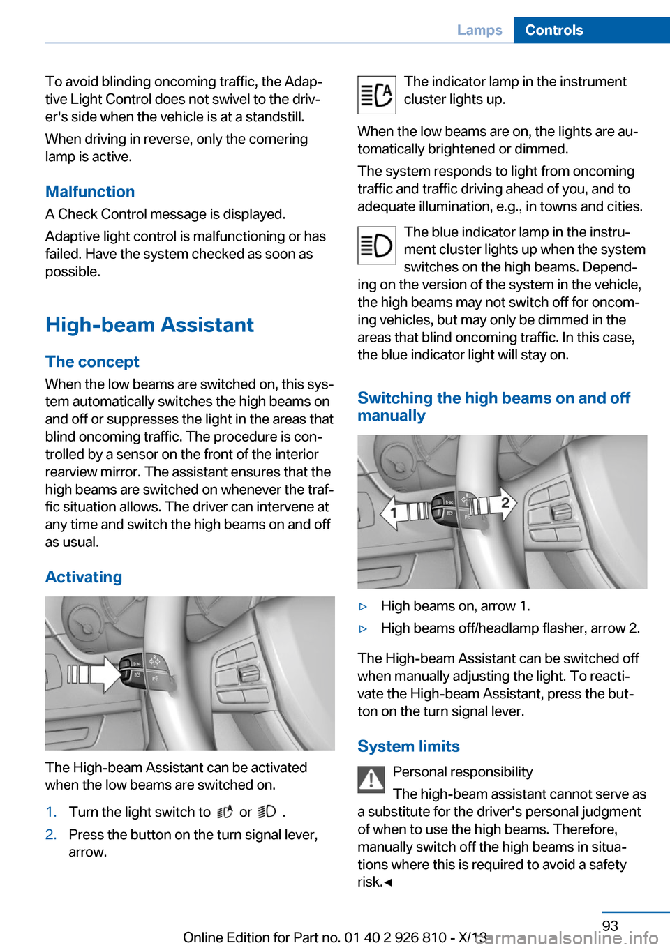
High-beam Assistant The concept
When the low beams are switched on, this sys‐
tem automatically switches the high beams on
and off or suppresses the light in the areas that
blind oncoming traffic. The procedure is con‐
trolled by a sensor on the front of the interior
rearview mirror. The assistant ensures that the
high beams are switched on whenever the traf‐
fic situation allows. The driver can intervene at
any time and switch the high beams on and off as usual.
Activating
The High-beam Assistant can be activated
when the low beams are switched on.
1.Turn the light switch to or .2.Press the button on the turn signal lever,
arrow.The indicator lamp in the instrument
cluster lights up.
When the low beams are on, the lights are au‐
tomatically brightened or dimmed.
The system responds to light from oncoming
traffic and traffic driving ahead of you, and to
adequate illumination, e.g., in towns and cities.
The blue indicator lamp in the instru‐
ment cluster lights up when the system
switches on the high beams. Depend‐
ing on the version of the system in the vehicle, the high beams may not switch off for oncom‐
ing vehicles, but may only be dimmed in the
areas that blind oncoming traffic. In this case,
the blue indicator light will stay on.
Switching the high beams on and off
manually▷High beams on, arrow 1.▷High beams off/headlamp flasher, arrow 2.
The High-beam Assistant can be switched off
when manually adjusting the light. To reacti‐
vate the High-beam Assistant, press the but‐
ton on the turn signal lever.
System limits Personal responsibility
The high-beam assistant cannot serve as
a substitute for the driver's personal judgment
of when to use the high beams. Therefore,
manually switch off the high beams in situa‐
tions where this is required to avoid a safety
risk.◀
Seite 93LampsControls93
Online Edition for Part no. 01 40 2 926 810 - X/13
Page 101 of 248
Protective action
Airbags are not triggered in every impact situa‐
tion, e.g., in less severe accidents or rear-end
collisions.
Information on how to ensure the optimal
protective effect of the airbags▷Keep at a distance from the airbags.▷Always grasp the steering wheel on the
steering wheel rim, holding your hands at
the 3 o'clock and 9 o'clock positions, to
keep the danger of injury to your hands or
arms as low as possible if the airbag is trig‐
gered.▷There should be no people, animals, or ob‐
jects between an airbag and a person.▷Do not use the cover of the front airbag on
the front passenger side as a storage area.▷Keep the dashboard and window on the
front passenger side clear, i.e., do not
cover with adhesive labels or coverings,
and do not attach holders such as for navi‐
gation instruments and mobile phones.▷Make sure that the front passenger is sit‐
ting correctly, i.e., keeps his or her feet and
legs in the footwell; otherwise, leg injuries
can occur if the front airbag is triggered.▷Do not place slip covers, seat cushions or
other objects on the front passenger seat
that are not approved specifically for seats
with integrated side airbags.▷Do not hang pieces of clothing, such as
jackets, over the backrests.▷Make sure that occupants keep their heads
away from the side airbag and do not rest
against the head airbag; otherwise, injuries
can occur if the airbags are triggered.▷Do not remove the airbag restraint system.▷Do not remove the steering wheel.▷Do not apply adhesive materials to the air‐
bag cover panels, cover them or modify
them in any way.▷Never modify either the individual compo‐
nents or the wiring in the airbag system.
This also applies to steering wheel covers,
the dashboard, the seats, the roof pillars
and the sides of the headliner.◀
Even when all instructions are followed closely,
injury from contact with the airbags cannot be
ruled out in certain situations.
The ignition and inflation noise may lead to
short-term and, in most cases, temporary
hearing impairment in sensitive individuals.
In the case of a malfunction, deactivation
and after triggering of the airbags
Do not touch the individual components imme‐
diately after the system has been triggered;
otherwise, there is the danger of burns.
Only have the airbags checked, repaired or dis‐
mantled and the airbag generator scrapped by
the service center or a workshop that has the
necessary authorization for handling explo‐
sives.
Non-professional attempts to service the sys‐
tem could lead to failure in an emergency or
undesired triggering of the airbag, either of
which could result in injury.◀
Warnings and information on the airbags are
also found on the sun visors.
Functional readiness of the airbag
system
When the ignition is switched on, the
warning lamp in the instrument cluster
lights up briefly and thereby indicates
the operational readiness of the entire airbag
system and the belt tensioner.
Airbag system malfunctioning
▷Warning lamp does not come on when the
ignition is turned on.▷The warning lamp lights up continuously.Seite 97SafetyControls97
Online Edition for Part no. 01 40 2 926 810 - X/13