119 BMW 318i 1992 E36 Workshop Manual
[x] Cancel search | Manufacturer: BMW, Model Year: 1992, Model line: 318i, Model: BMW 318i 1992 E36Pages: 759
Page 3 of 759
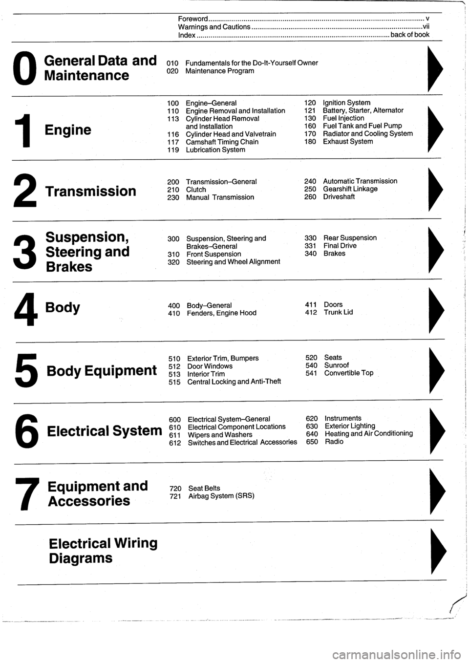
General
Data
and
010
FundamentalsfortheDo-lt-YourselfOwner
Maintenance
020
Maintenance
Program
Engine
Transmission
Suspension,
Steering
and
Brakes
4
Body
100
Engine-General
110
Engine
Removal
and
Installation
113
Cylinder
Head
Removal
and
Installation
116
Cylinder
Head
and
Valvetrain
117
Camshaft
Timing
Chain
119
Lubrication
System
200
Transmission-General
210
Clutch
230
Manual
Transmission
510
Exterior
Trim,
Bumpers
520
Seats
Bo
y
Equipment
512
DoorWTdws
540
nr
t
513
InteriorTrim
541
Convertible
Top
515
Central
Locking
and
Anti-Theft
600
Electrical
System-General
620
Instruments
Electrical
S
stem
610
Electrical
Component
Locations
630
Exterior
Lighting
611
Wipers
and
Washers
640
Heating
and
Air
Conditioning
6
612
Switches
and
Electrical
Accessories
650
Radio
Equipment
and
720
SeatBelts
Accessories
721
Airbag
System
(SRS)
Electrical
Wiring
Diagrams
Foreword
.
...
.
.
.
..................
.
.
.
.....
.
............
.
...
.
.
.
.
.
................
.
.
.
.....
.
......
.
................
.
.
.
.....
v
Warnings
and
Cautions
.....
.
...
.
.
.
.
.
..........
.
...
.
.
.
.
.
......
.
.........
.
.
.
...
.
.
.
......
.
.
.
.
.
............
.
.
.
.
.
.
.vii
Index
..............
.
.
.
.....
.
............
.
...
.
.
.
.
.
........
.
...
.
.
.
.
.
.......
.
......
.
...
.
.
.
.
.
.
.
........
.
.
.
..
back
of
book
300
Suspension,
Steering
and
330
RearSuspension
Brakes-General
331
Final
Drive
310
Front
Suspension
340
Brakes
320
Steering
and
Wheel
Alignment
400
Body-General
411
Doors
410
Fenders,
Engine
Hood
412
Trunk
Lid
120
Ignition
System
121
Battery,Starter,
Alternator
130
Fue¡
Injection
160
Fuel
Tank
and
Fuel
Pump
170
Radiator
and
Cooling
System180
Exhaust
System
240
Automatic
Transmission
250
Gearshift
Linkage
260
Driveshaft
Page 21 of 759
If
steam
is
coming
from
the
engine
compartment
thenthere
is
With
the
engine
and
ignition
off,
check
for
loose
or
corroded
most
likely
a
burst
coolant
hose
or
a
large
leak
in
the
cooling
battery
cables
or
wires
at
the
battery
or
thealtemator
.
Discon-
system
.
To
find
the
leak,
look
for
signs
of
coolant
leakage
on
necting,
cleaning,
and
reinstalling
corroded
wires
and
connec-
hoses,
at
hose
connections,
or
on
the
radiator
.
Let
theengine
tors
may
solve
the
problem
.
Also
check
drive
belt
tension
as
cool
thoroughly,
then
add
coolant
or
water
to
fill
the
system
and
described
in
020
Maintenance
Program
.
start
the
engine
.
If
a
great
deal
of
water
or
coolant
flows
out
of
the
hole,
then
thecarshouldnot
be
driven
until
repairs
are
made
.
lf
there
is
slight
seepage,
then
it
may
be
possible
to
drive
TOWi
ng
a
short
distance,
adding
coolant
as
needed
.
The
cars
covered
by
this
manual
should
be
towed
witha
tow
truck
using
wheel
lift
or
flat
bed
equipment
.
Do
not
tow
thecar
on
all
four
wheels
except
for
very
short
distances
to
move
it
to
a
safe
place
.
If
thered
engine
oil
pressure
warning
light
illuminates,
imme-
diately
stop
thecar
and
turn
off
the
engine
.
Have
the
vehicle
A
towing
eye
is
provided
in
the
luggage
compartment
tool
kit
.
flat-bedded
or
towed
to
an
authorized
service
center
and
have
The
towing
eye
can
be
screwed
into
the
front
or
rear
bumper
.
the
engine
oil
pressure
checked
.
See
Fig
.
18
and
Fig
.
19
.
Low
Oil
Pressure
NOTE-
Detafed
information
on
checking
the
oil
pressure
is
covered
ín
119
Lubrication
System
.
Brake
Fluid
Leve¡
The
brake
fluid
leve¡
warning
light
may
bean
indicator
of
brake
fluid
loss
.
Problems
with
the
brakesystem
should
be
checked
and
repaired
immediately
.
See
340Brakes
for
more
information
.
Check
Engine
Warning
Light
Dim
Lights
FUNDAMENTALS
FOR
THE
DO-IT
YOURSELF
OWNER
010-13
If
the
"CHECK
ENGI
NE"
warning
light
comes
on
or
flashes,
it
indicates
that
an
emissions-related
fault
has
occurred
.
Faults
suchas
a
failed
oxygen
sensor
or
a
faultyfuelinjector
can
tum
the
light
on,
causing
the
exhaust
or
evaporative
emissions
to
exceed
a
specified
limit
.
The
engine
can
be
safely
driven
with
the
light
on,
although
the
emission
systems
should
be
checked
assoonas
possible
.
See
100
Engine-General
for
more
infor-
mation
on
the
Check
Engine
Light
and
the
On-board
diagnostic
system
.
Headlights
and
instrument
panel
illuminationthat
are
dim
or
gradually
getting
dimmer
generally
indicate
a
problem
with
the
battery
or
charging
system
.
The
battery
charge
indicator
light
may
come
on
as
the
lights
are
dimming
.
In
either
case,
theen-
gine
and
accessories
are
running
off
of
the
battery
alone,
and
will
soon
discharge
it
altogether
.
If
possible,
do
not
stop
the
engine
unless
you
have
the
capa-
bility
to
jump
start
¡t
.
There
may
not
be
enough
power
in
the
starting
system
torestart
the
engine
.
Instead,turn
off
as
many
electrical
consumers
as
possible
.
This
will
reduce
the
current
drain
and
will
allow
thecar
to
be
driven
farther
before
you
lose
all
battery
power
.
Fig
.
18
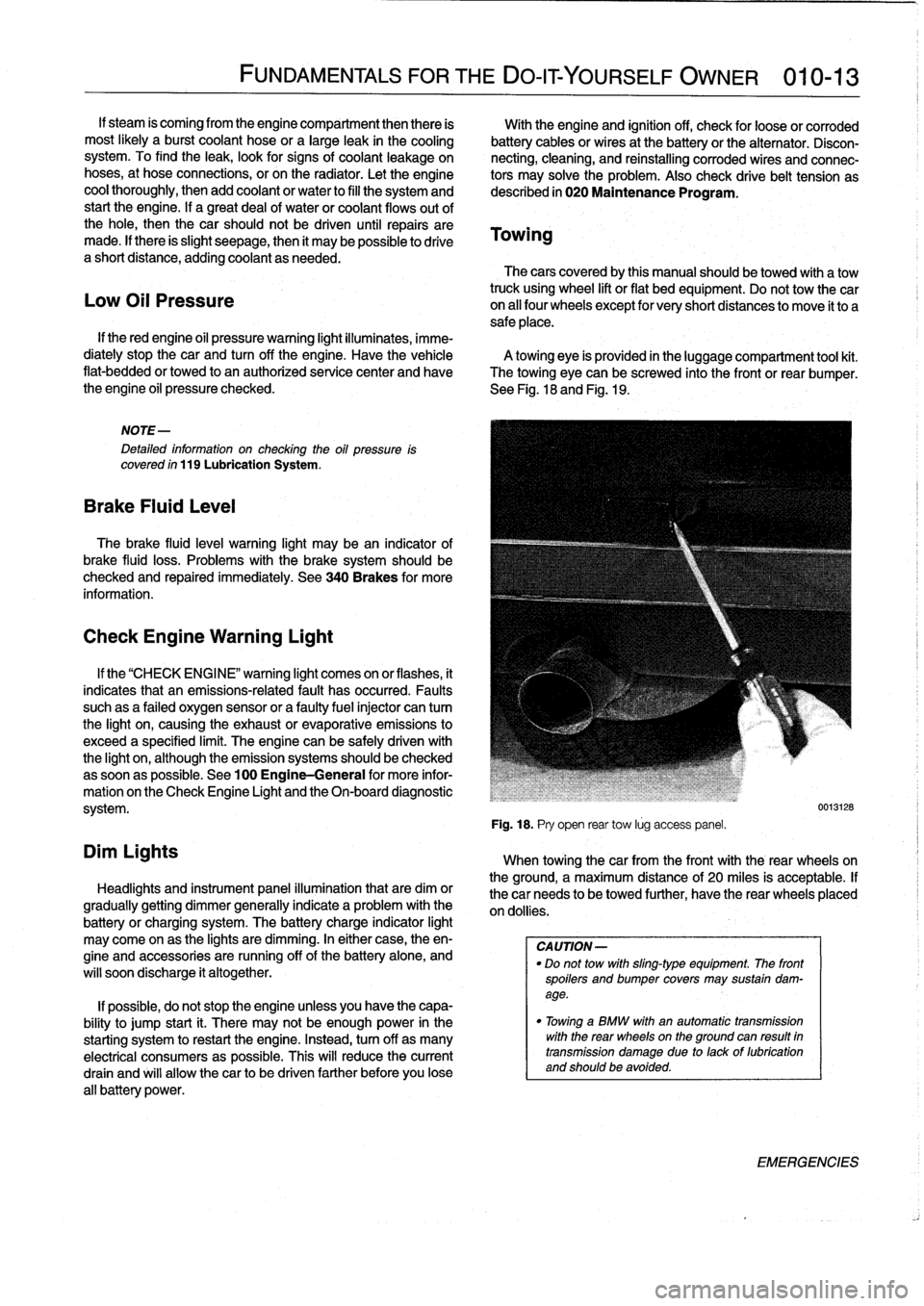
.
Pry
open
rear
tow
lúg
access
panel
.
When
towingthecar
from
the
front
with
the
rear
wheelson
the
ground,
a
maximum
distance
of
20
miles
is
acceptable
.
If
thecar
needs
to
be
towed
further,
have
the
rear
wheels
placed
on
dollies
.
CA
UTION-
"
Do
not
tow
with
sling-type
equipment
The
front
spoilers
andbumper
covers
may
sustain
dam-
age
.
"
Towínga
BMW
with
an
automatic
transmission
with
the
rear
wheelson
the
ground
can
resuft
in
transmission
damage
due
to
lackof
lubrication
and
should
be
avoided
.
0013128
EMERGENCIES
Page 23 of 759
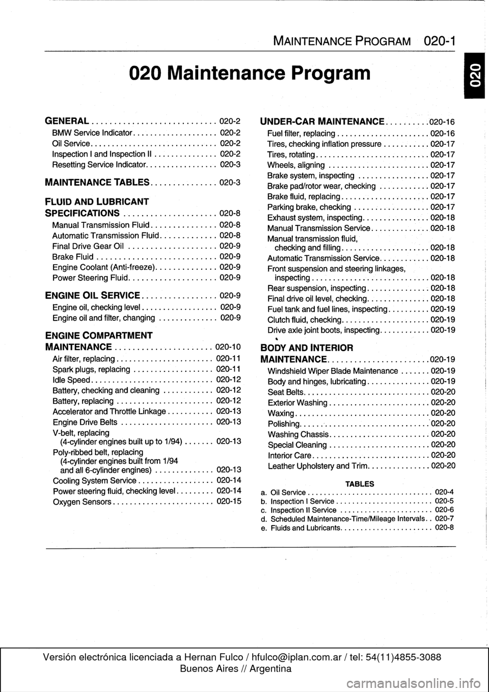
020
Maintenance
Program
GENERAL
.
.
...
.
.
.
...
.
.
.
.
.
.
.
.
.
.
.
...
.
..
020-2
BMW
Service
Indicator
......
..
....
..
...
..
.
020-2
Oil
Service
.....
.
..........
..
...
...
...
..
.
020-2
Inspection
I
and
Inspection
II
.
..
....
..
...
..
.
020-2
Resetting
Service
Indicator
....
.
....
..
...
..
.
020-3
MAINTENANCE
TABLES
..
.
.
.
.
.
........
020-3
FLUID
AND
LUBRICANT
SPECIFICATIONS
.
.
.
.
.
.
.
...
.
.
.
....
.
...
020-8
Manual
Transmission
Fluid
..
.
.
.
.
.
....
.
.
.
.
020-8
Automatic
Transmission
Fluid
.
.
.
.
.
....
.
.
.
.
020-8
Final
Drive
Gear
Oil
................
.
.
.
.
020-9
Brake
Fluid
.
.
.
.
.
................
.
.
.
.
020-9
Engine
Coolant
(Anti-freeze)
.
.
...
.
....
.
.
.
.
020-9
Power
Steering
Fluid
........
..
......
.
.
.
.
020-9
ENGINE
OIL
SERVICE
.
.
...
.
.
.
...
.
.
.
.
.
.
020-9
Engine
oil,
checking
leve¡
..
...
...
..
........
020-9
Engine
oil
and
filter,
changing
....
.
......
.
..
020-9
ENGINE
COMPARTMENT
MAINTENANCE
...
.
.
.
.
.
.
.
.
.
.
.
.
.
......
020-10
Air
filter,
replacing
.
...
...
.
.....
.
.....
.
...
020-11
Spark
plugs,
replacing
...
.
......
.
...
..
...
020-11
¡dle
Speed
.
..
...
...
....
.
......
.
...
..
...
020-12
Battery,
checking
and
cleaning
.......
..
...
020-12
Battery,
replacing
.
.....
.
.....
.
.....
..
...
020-12
Accelerator
and
Throttle
Linkage
.
.....
..
...
020-13
Engine
DriveBelts
.....
.
....
..
...
...
...
.
020-13
V-belt,
replacing
(4-cylinder
engines
built
up
to
1/94)
..
....
.
020-13
Poly-ribbed
belt,
replacing
(4-cylinder
engines
built
from
1194
and
all
6-cylinder
engines)
.
.
....
..
......
020-13
Cooling
System
Service
.
...
..
....
..
....
..
020-14
Power
steering
fluid,
checking
leve¡
.
..
....
.
.
020-14
Oxygen
Sensors
....
...
..
..
....
.
.....
.
.
020-15
MAINTENANCE
PROGRAM
020-1
UNDER-CAR
MAINTENANCE
.
..
.
...
.
.
.020-16
'
Fuel
filter,
replacing
...
.
.....
..
.....
..
..
.020-16
Tires,
checking
inflation
pressure
.
.....
.
....
020-17
Tires,
rotating
...
..
.....
..
....
..
....
.
....
020-17
Wheels,
aligning
..
.....
.
...........
.
....
'020-17
Brake
system,
inspecting
.
.
....
.
.....
..
...
020-17
Brake
pad/rotor
wear,checking
.
......
.
....
020-17
Brake
fluid,
replacing
.........
..
.
..
..
.
020-17
Parking
brake,
checking
......
.
.....
..
....
020-17
Exhaust
system,
inspecting
....
..
.....
.
...
.020-18
Manual
Transmission
Senrice
..
..
.....
.
....
020-18
Manual
transmission
fluida
checking
and
filling
..
.
....
..
.
.
..
..
....
020-18
AutomaticTransmission
Service
.
....
...
....
020-18
Front
suspension
and
steeringlinkages,
inspecting
..
.
:.....
.
....
..
.....
..
...
.
.020-18
Rear
suspension,
inspecting
.
..
...
...
....
..
020-18
Final
drive
oil
leve¡,
checking
.
.
.
...
....
...
..
020-18
Fuel
tank
and
fuel
lines,
inspecting
.
.....
....
020-19
Clutch
fluid,
checking
...
...
...
...
....
.....
020-19
Drive
axle
joint
boots,
inspecting
...
..
.....
..
020-19
BODY
AND
INTERIOR
MAINTENANCE
.
.
.
.
.
.
.
.
.
.
.
.
.
.
.
.
.
.
...
.
.020-19
Windshield
Wiper
Blade
Maintenance
....
.
.
020-19
Body
and
hinges,
lubricating
.
.....
..
......
.
020-19
Seat
Belts
...
..
...
...
...
..
.....
..
.....
.
.
020-20
Exterior
Washing
..
...
...
..
.
.
...
..
......
.020-20
Waxing
.....
..
...
...
...
..
.....
..
.......
020-20
Polishing
..
...
...
...
....
..
..........
..
.
.'020-20
Washing
Chassis
.
...
....
.
....
..
.....
.
...
020-20
Special
Cleaning
.
.
.....
..
...
.
.....
..
..
.020-20
Interior
Care
.
....
..
....
..
..
.
.
......
.
...
020-20
Leather
Upholstery
and
Trim
...
..
....
...
...
020-20
TABLES
a
.
Oil
Service
......
...
.
..
.............
...
---
020-4
b
.
Inspection
1
Service
..
.
.
.............
....
...
020-5
c
.
Inspection
11
Service
.
.
...
...........
..
.
..
..
020-6
d
.
Scheduled
Maintenance-Time/Mileage
Intervals
..
020-7
e
.
Fluids
and
Lubricants
..
...
...........
.....
..
020-8
Page 35 of 759
Accelerator
and
Throttle
Linkage
The
accelerator
and
throttie
linkage
should
be
lubricated
pe-
riodically
.
Use
a
general
purpose
oil
on
the
joints
and
bearings
of
the
linkage
.
Use
a
multipurpose
grease
on
the
bearing
points
of
the
throttie
plate
.
Engine
Drive
Belts
Drive
belts
and
pulleys
transfer
power
from
theengine
crank-
shaft
to
various
accessories
.
See
Fig
.
13
.
Depending
on
model
and
model
year,
engine
driven
accessories
are
driven
by
V-
belts,
poly-ribbed
(serpentine)
belts,
or
a
combination
of
the
two
.
For
example,
early
4-cylinder
engines,
usetwo
V-belts
and
one
poly-ribbed
belt
.
Inspect
drivebelts
with
the
engine
off
.
lf
the
belt
shows
signs
of
wear,
cracking,
glazing,
or
missing
sections,
it
should
be
re-
placed
immediately
.
V
belt,
replacing
(4-cylinder
engines
built
up
to
1194)
0012472
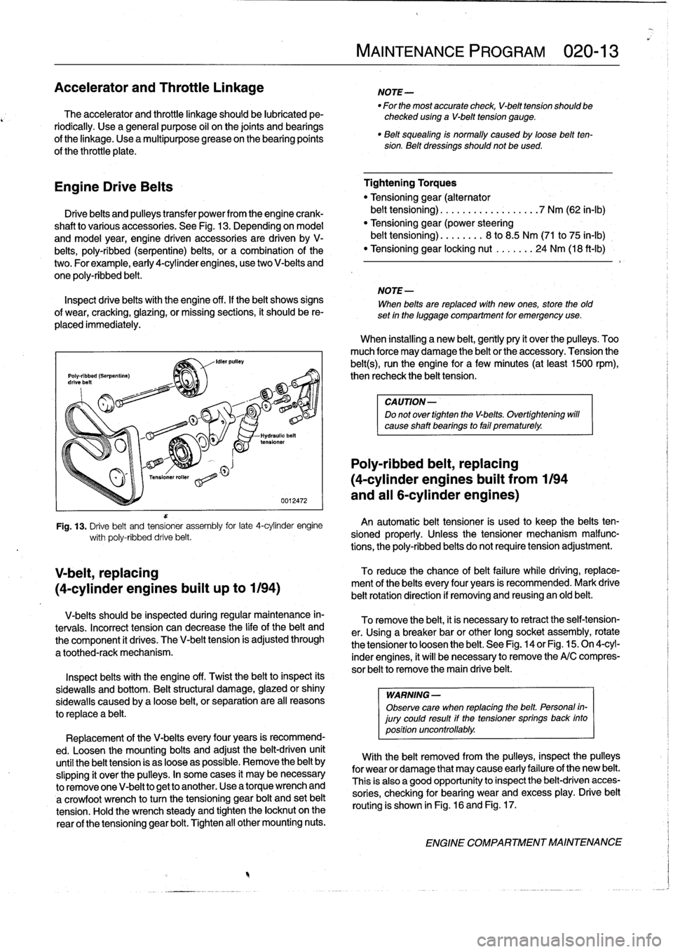
Fig
.
13
.
Drive
belt
and
tensioner
assembly
for
late
4-cylinder
engine
wíth
poly-ribbed
drive
belt
.
V-belts
should
be
inspected
during
regular
maintenance
in-
tervais
.
Incorrect
tension
can
decrease
the
life
of
the
belt
and
the
component
it
drives
.
The
V-belt
tension
is
adjusted
through
a
toothed-rack
mechanism
.
Inspect
belts
with
the
engine
off
.
Twist
the
beltto
inspect
its
sidewalls
and
bottom
.
Beltstructural
damage,
glazed
or
shiny
sidewaljs
caused
by
a
loose
belt,
orseparation
are
al¡
reasons
to
replace
a
belt
.
Replacement
of
the
V-belts
every
four
years
is
recommend-
ed
.
Loosen
the
mounting
bolts
and
adjust
the
belt-driven
unit
until
the
belt
tension
is
as
loose
aspossible
.
Remove
the
belt
by
slipping
it
over
the
pulleys
.
In
some
cases
it
may
be
necessary
to
removeone
V-belt
to
get
to
another
.
Use
a
torque
wrench
and
a
crowfoot
wrench
to
turn
the
tensioning
gear
bolt
and
set
belt
tension
.
Hold
the
wrench
steady
and
tighten
the
locknut
on
the
rear
of
the
tensioning
gear
bolt
.
Tighten
al¡
other
mounting
nuts
.
MAINTENANCE
PROGRAM
020-
1
3
NOTE-
"
For
the
most
accurate
check,
V-belt
tension
should
be
checked
using
a
V-belt
tension
gauge
.
"
Belt
squealing
is
normally
caused
by
loose
beltten-sion
.
Belt
dressings
should
not
be
used
.
Tightening
Torques
"
Tensioning
gear
(alternator
belt
tensioning)
.
.
.
...............
7
Nm
(62
in-lb)
"
Tensioning
gear(power
steering
belt
tensioning)
...
..
...
8
to
8
.5
Nm
(71
to
75
in-lb)
"
Tensioning
gear
locking
nut
.......
24
Nm
(18
ft-Ib)
NOTE-
When
belts
are
replaced
with
new
ones,
store
the
old
set
in
the
luggage
compartment
for
emergency
use
.
When
installing
a
new
belt,
gently
pry
it
over
the
pulleys
.
Too
much
force
may
damage
the
belt
or
the
accessory
.
Tension
the
belt(s),
runthe
engine
for
a
few
minutes
(at
least
1500
rpm),
then
recheck
the
belt
tension
.
CAUTION-
Do
not
over
tighten
the
V-belts
.
Overtightening
will
cause
shaft
bearings
to
fail
prematurely
.
Poly-ribbed
belt,
replacing
(4-cylinder
engines
buiit
from
1194
and
all
6-cylinder
engines)
An
automatic
belt
tensioner
is
used
to
keep
the
belts
ten-
sioned
properly
.
Unless
the
tensioner
mechanism
malfunc-
tions,
the
poly-ribbed
belts
do
not
require
tension
adjustment
.
To
reduce
the
chance
ofbelt
failure
while
driving,
replace-
ment
of
the
belts
every
four
years
is
recommended
.
Mark
drive
belt
rotationdirectíon
if
removing
and
reusing
an
old
belt
.
To
remove
the
belt,
it
is
necessary
toretract
the
self-tension-
er
.
Using
a
breaker
bar
or
other
long
socket
assembly,
rotate
the
tensioner
to
loosenthe
belt
.
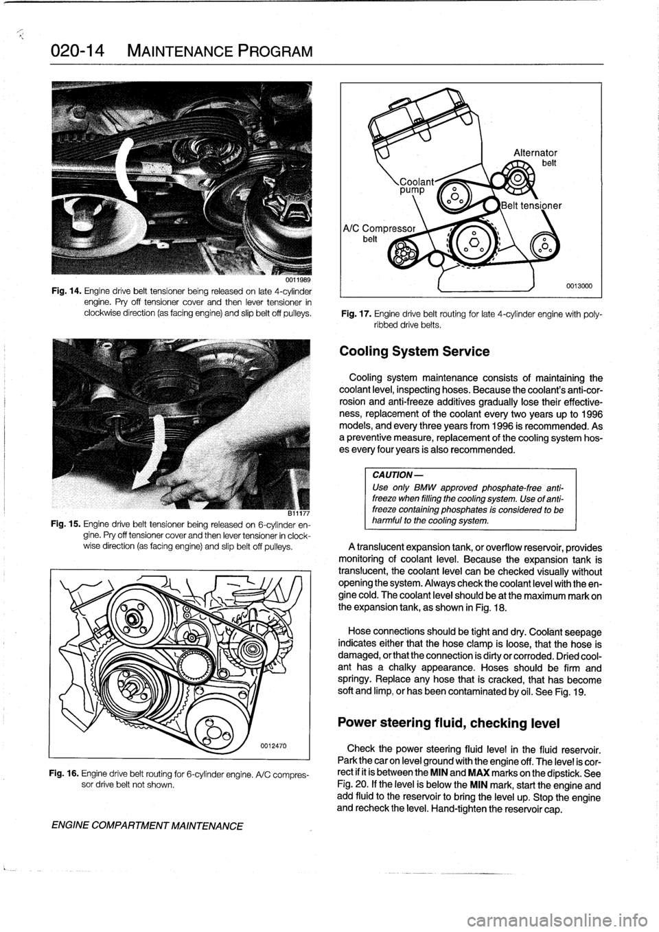
See
Fig
.
14
or
Fig
.
15
.
On
4-cyl-
inder
engines,
it
will
benecessary
to
remove
the
A/C
compres-
sor
belt
to
remove
the
main
drive
belt
.
WARNING
-
Observe
care
when
replacing
the
belt
.
Personal
in-
jury
could
result
if
the
tensioner
springs
back
into
position
uncontrollably
.
With
the
belt
removed
from
the
pulleys,
inspect
the
pulleys
for
wear
or
damage
that
may
cause
early
failureof
the
new
belt
.
This
is
also
a
good
opportunity
to
inspect
the
belt-driven
acces-
sories,
checking
for
bearing
wear
and
excess
play
.
Drive
belt
routing
is
shown
in
Fig
.
16
and
Fig
.
17
.
ENGINE
COMPARTMENT
MAINTENANCE
Page 36 of 759
020-
1
4
MAINTENANCE
PROGRAM
uu11989
Fig
.
14
.
Engine
drive
belt
tensíoner
being
released
on
late
4-cylinder
engine
.
Pry
off
tensioner
cover
and
then
lever
tensioner
in
clockwise
direction
(as
facing
engine)
and
slip
beltoff
pulleys
.
Fig
.
17
.
Engine
drive
belt
routing
for
late
4-cylinder
engine
with
poly-
ribbed
drivebelts
.
CA
UTION-
Use
only
BMW
approved
phosphate-free
anti-
freeze
when
filling
the
cooling
system
.
Use
of
anti-
B11177
freeze
containing
phosphates
!s
considerad
to
be
Fig
.
15
.
Engine
drive
belt
tensioner
being
released
on
6-cylinder
en-
harmful
to
the
cooling
system
.
gine
.
Pry
off
tensioner
cover
and
then
lever
tensioner
in
clock-
wise
direction
(as
facing
engine)
and
slipbelt
off
pulleys
.
A
translucent
expansion
tank,
or
overflow
resenroir,
providesmonitóring
of
coolant
leve¡
.
Because
the
expansion
tank
is
translucent,
thecoolant
level
can
be
checked
visually
without
opening
the
system
.
Always
check
thecoolant
leve¡
with
theen-gine
cold
.
The
coolant
leve¡
should
be
at
the
maximum
mark
on
O
o
'~
I
the
expansion
tank,
as
shown
in
Fig
.
18
.
OO
Hose
connectionhld
b
tiht
s
soueg
an
ddry
.
Coolánt
seepage
indicates
either
that
the
hose
clamp
is
loose,
that
the
pose
is
ENGINE
COMPARTMENT
MAINTENANCE
0012470
Fig
.
16
.
Engine
drive
belt
routing
for
6-cylinder
engine
.
A/C
compres-
sor
drive
belt
not
shown
.
'92
irá
Alternator
belt
Coolant~
0
pp
o0o
Belt
tensioner
Cooling
System
Service
0013000
Cooling
system
maintenance
consists
of
maíntaining
thecoolant
leve¡,
inspecting
hoses
.
Because
the
coolant's
anti-cor-
rosion
and
anti-freeze
additives
gradually
lose
their
effective-
ness,
replacement
of
thecoolant
every
two
years
up
to
1996
models,
and
every
three
years
from
1996
is
recommended
.
Asa
preventive
measure,
replacement
of
the
cooling
system
hos-
es
every
four
years
is
also
recommended
.
damaged,
or
that
the
connection
is
dirty
or
corroded
.
Dried
cool-
ant
has
a
chalky
appearance
.
Hoses
should
be
firm
and
springy
.
Replace
any
hose
that
is
cracked,
that
has
become
soft
and
limp,
or
has
been
contaminated
by
oil
.
See
Fig
.
19
.
Power
steering
fluid,
checking
leve¡
Check
the
power
steering
fluid
level
in
the
fluid
reservoir
.
Park
thecar
on
leve¡
ground
with
the
engine
off
.
The
level
is
cor-
rect
if
it
is
between
the
MIN
and
MAX
marks
on
the
dipstick
.
See
Fig
.
20
.
If
the
leve¡
is
below
the
MIN
mark,
start
the
engine
andadd
fluid
to
the
reservoir
to
bríng
the
leve¡
up
.
Stop
the
engine
and
recheck
the
leve¡
.
Hand-tighten
the
reservoir
cap
.
Page 40 of 759
020-
1
8
MAINTENANCE
PROGRAM
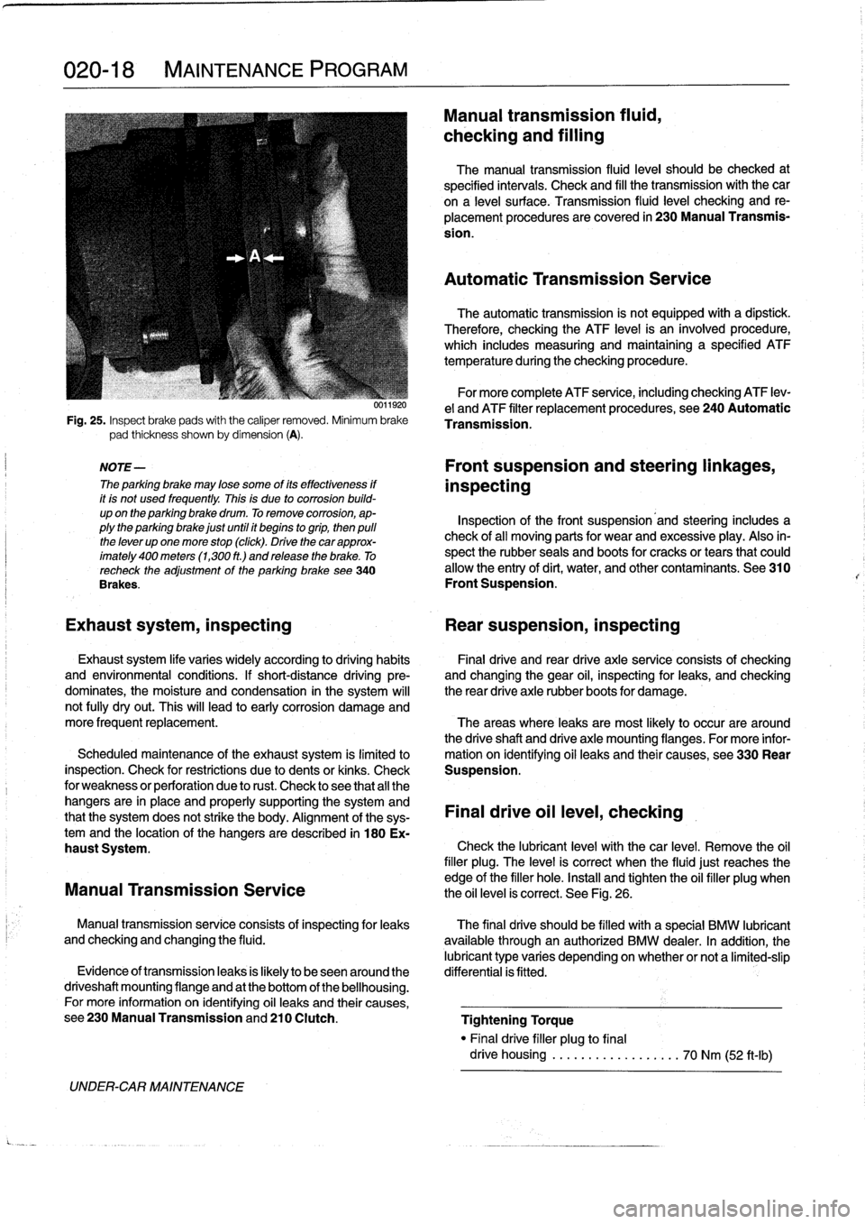
Fig
.
25
.
Inspect
brake
pads
with
the
caliper
removed
.
Minimum
brake
pad
thickness
shown
by
dimension
(A)
.
NOTE-
The
parking
brake
may
lose
some
of
its
effectiveness
if
it
is
not
used
frequently
.
This
is
due
to
corrosion
build-
up
on
the
parking
brake
drum
.
To
remove
corrosion,
ap-
plythe
parking
brake
just
until
it
begins
togrip,
then
pulí
the
lever
up
one
more
stop
(click)
.
Drive
thecar
approx-
imately
400
meters
(1,300
ft
.)
and
release
the
brake
.
To
recheck
the
adjustment
of
the
parking
brake
see340
Brakes
.
UNDER-CAR
MAINTENANCE
0011920
Manual
transmission
fluid,
checking
and
filling
The
manual
transmission
fluid
leve¡
should
be
checked
at
specified
intervals
.
Check
and
fill
the
transmission
with
the
car
ona
leve¡
surface
.
Transmission
(luid
leve¡
checking
and
re-
placement
procedures
are
covered
in
230
Manual
Transmis-
sion
.
Automatic
Transmission
Service
The
automatic
transmission
is
not
equipped
with
a
dipstíck
.
Therefore,
checking
the
ATF
level
is
an
ínvolved
procedure,
which
includes
measuring
and
maintaining
a
specified
ATF
temperature
during
the
checking
procedure
.
For
more
complete
ATF
service,
including
checking
ATF
lev-
e¡
and
ATF
filter
replacement
procedures,
see
240
Automatic
Transmission
.
Front
suspension
and
steering
linkages,
inspecting
Inspection
of
the
front
suspension'and
steering
includes
a
check
of
all
moving
parts
for
wear
and
excessive
play
.
Also
in-
spect
the
rubber
seals
and
boots
for
cracks
or
tears
that
could
allow
the
entry
of
dirt,
water,
and
other
contaminants
.
See
310
Front
Suspension
.
Exhaust
system,
inspecting
Rear
suspension,
inspecting
Exhaust
system
life
varies
widely
according
to
driving
habits
Final
drive
and
rear
drive
axle
service
consists
of
checking
and
environmental
conditions
.
If
short-distance
driving
pre-
and
changing
the
gear
oil,
inspecting
for
leaks,
and
checking
dominates,
the
moisture
and
condensation
in
the
system
will
the
rear
drive
axle
rubber
boots
for
damage
.
not
fully
dryout
.
This
will
lead
to
early
corrosion
damage
and
more
frequent
replacement
.
The
areas
where
leaks
are
most
likely
to
occur
are
around
the
driveshaft
and
drive
axle
mounting
flanges
.
For
more
infor
Scheduled
maintenance
of
the
exhaust
system
is
limitedlo
mation
on
ídentifying
oil
leaks
and
their
causes,
see330
Rear
inspection
.
Check
for
restrictions
due
to
dents
or
kinks
.
Check
Suspension
.
for
weakness
or
perforation
due
to
rust
.
Check
lo
see
that
all
the
hangers
are
in
place
and
properly
supporting
the
system
and
that
the
system
does
not
strike
the
body
.
Alignment
of
the
sys-
Final
drive
oil
leve¡,
checking
temand
the
location
of
the
hangers
aredescribed
in
180
Ex-
haust
System
.
Check
the
lubricant
leve¡
with
thecar
level
.
Remove
the
oil
filler
plug
.
The
leve¡
is
correct
when
the
fluidjust
reaches
the
edge
of
the
filler
hole
.
Install
and
tighten
the
oil
filler
plug
when
Manual
Transmission
Service
the
oil
level
is
correct
.
See
Fig
.
26
.
Manual
transmissionservice
consists
of
inspectingfor
leaks
The
final
drive
should
be
filled
with
a
special
BMW
lubricant
and
checking
and
changing
the
fluid
.
available
through
an
authorized
BMW
dealer
.
In
addition,
the
lubricant
type
varies
depending
onwhether
or
nota
limited-slip
Evidence
of
transmissionleaks
is
fkely
to
beseenaround
the
differential
is
fitted
.
driveshaft
mounting
flange
and
at
the
bottom
of
the
bellhousing
.
For
more
information
on
identifying
oil
leaks
and
their
causes,
see230ManualTransmissionand210
Clutch
.
Tightening
Torque
"
Finaldrive
filler
plug
to
final
drive
housing
..................
70
Nm
(52
ft-Ib)
Page 47 of 759
ignition
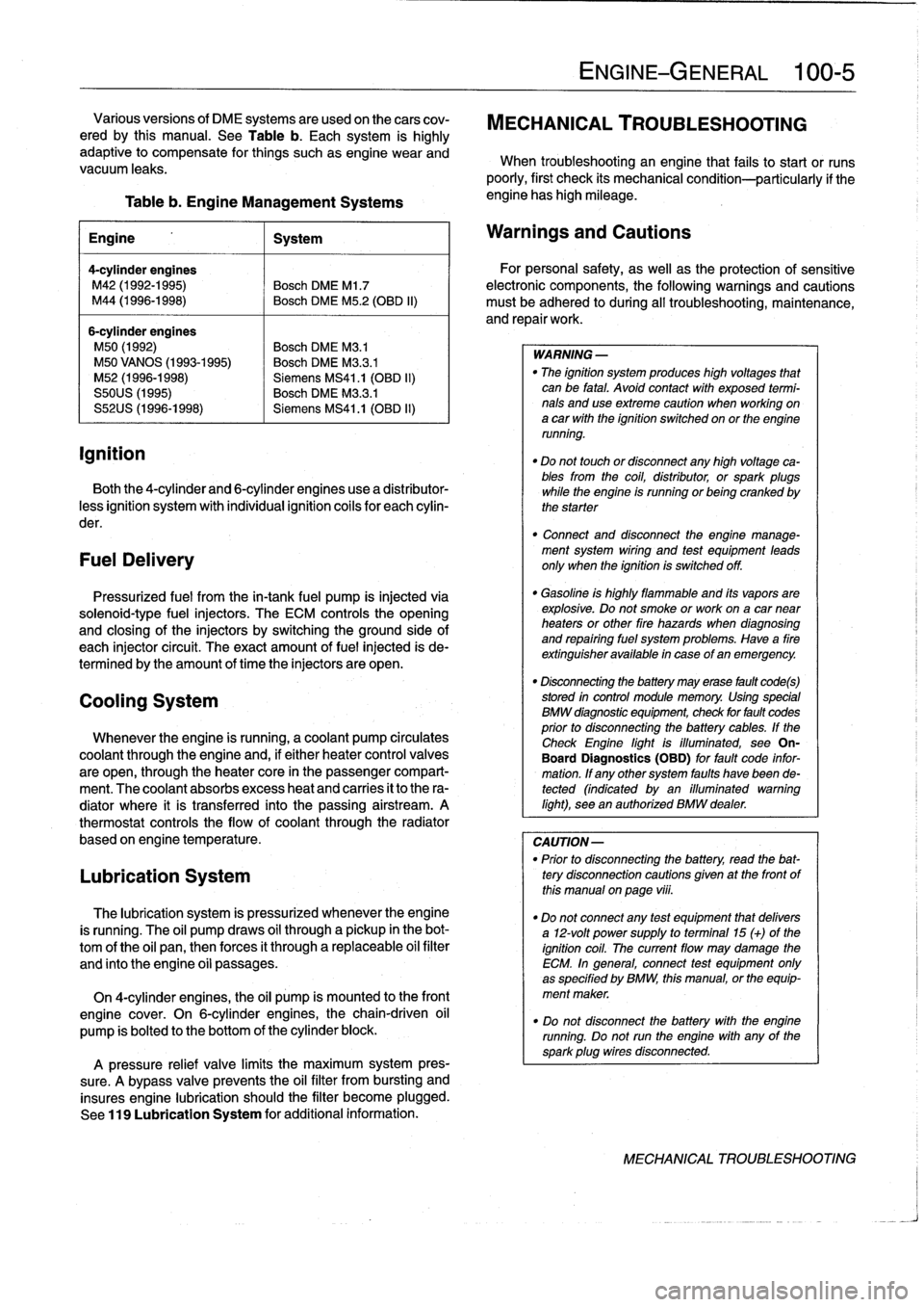
Table
b
.
Engine
Management
Systems
engine
has
high
mileage
.
Engine
1
System
4-cylinder
engines
M42
(1992-1995)
Bosch
DME
Ml
.7
M44
(1996-1998)
Bosch
DME
M5
.2
(OBD
II)
6-cylinder
engines
M50
(1992)
Bosch
DME
M3
.1
M50
VANOS
(1993-1995)
Bosch
DME
M3
.3
.1
M52
(1996-1998)
Siemens
MS41
.1
(OBD
II)
S50US
(1995)
Bosch
DME
M3
.3
.1
S52US
(1996-1998)
Siemens
MS41
.1
(OBD
II)
Both
the
4-cylinder
and
6-cylinder
engines
use
a
distributor-
less
ignition
system
with
individual
ignition
coils
for
each
cylin-
der
.
FuelDelivery
Pressurized
fuel
from
the
in-tank
fuel
pump
is
injected
via
solenoid-type
fuel
injectors
.
The
ECM
controls
the
opening
and
closing
of
the
injectors
by
switchingthe
ground
side
of
each
injector
circuit
.
The
exact
amount
of
fuel
injected
is
de-
termined
by
the
amount
of
timethe
injectors
are
open
.
Cooling
System
Whenever
the
engine
is
running,
acoolant
pump
circulates
coolant
through
the
engine
and,
if
either
heater
control
valves
are
open,
through
the
heater
core
in
the
passenger
compart-
ment
.
The
coolant
absorbs
excess
heat
and
carries
it
to
the
ra-
diator
where
it
is
transferred
into
the
passing
airstream
.
A
thermostat
controls
the
flow
of
coolant
through
the
radiator
based
on
engine
temperature
.
Lubrication
System
The
lubrication
system
is
pressurized
whenever
theengine
is
running
.
The
oil
pump
draws
oil
through
a
pickup
in
the
bot-
tom
of
the
oil
pan,thenforces
it
through
a
replaceable
oil
filter
and
finto
the
engine
oíi
passages
.
On
4-cylinder
engines,
the
oil
pump
is
mounted
to
the
front
engine
cover
.
On
6-cylinder
engines,thechain-driven
oil
pump
is
bolted
to
the
bottom
of
the
cylinder
block
.
A
pressure
relief
valve
limits
the
maximum
system
pres-
sure
.
A
bypass
valve
prevents
the
oil
filter
from
bursting
and
insures
engine
lubrication
should
the
filter
become
plugged
.
See
119
Lubrication
System
for
additional
information
.
ENGINE-GENERAL
100-
5
Various
versions
of
DME
systems
are
usedon
thecars
cov-
MECHANICAL
TROUBLESHOOTING
ered
by
this
manual
.
See
Table
b
.
Each
system
is
highly
adaptive
to
compensate
for
things
suchasengine
wear
and
When
troubleshooting
an
engine
that
fails
to
start
or
runs
vacuum
leaks
.
poorly,
first
check
its
mechanical
condition-particularly
if
the
Warnings
and
Cautions
For
personal
safety,
as
well
asthe
protection
of
sensitive
electronic
components,
the
following
warnings
and
cautions
must
be
adhered
to
during
all
troubleshooting,
maintenance,
and
repairwork
.
WARNING
-
"
The
ignition
system
produces
high
voltages
that
can
be
fatal
.
Avoid
contact
with
exposed
termi-
nals
anduse
extreme
caution
when
working
on
a
car
with
the
ignition
switched
on
or
the
engine
running
.
"
Do
not
touch
or
disconnect
any
high
voltage
ca-
bles
from
the
coil,
distributor,
orspark
plugs
while
the
engine
is
running
or
being
cranked
by
the
starter
"
Connect
and
disconnect
the
engine
manage-
ment
system
wiring
and
test
equipment
leads
only
when
the
ignition
is
switched
off
.
"
Gasoline
is
highly
flammable
and
its
vapors
are
explosive
.
Do
not
smoke
or
work
on
a
car
near
heaters
or
other
fire
hazards
when
diagnosing
and
repairing
fuel
system
problems
.
Have
a
fire
extínguisher
available
in
case
of
an
emergency
.
"
Disconnecting
the
battery
may
erase
fault
code(s)
stored
in
control
module
memory
.
Using
special
BMW
diagnosnnc
equipment,
check
for
fault
codes
prior
to
disconnecting
the
battery
cables
.
If
the
Check
Engine
lightis
illuminated,
see
On-
Board
Diagnostics
(OBD)
forfault
code
infor-
mation
.
If
any
other
system
faults
havebeen
de-tected
(indicated
byan
illuminated
warning
light),
see
an
authorized
BMW
dealer
.
CAUTION-
"
Prior
to
disconnecting
the
battery,
read
the
bat-
tery
disconnection
cautions
gíven
at
the
front
of
this
manual
on
page
viii
.
"
Do
notconnect
any
test
equipment
that
delivers
a
12-volt
power
supply
to
terminal15
(+)
of
the
ignition
coil
.
The
current
flow
may
damage
the
ECM
.
In
general,
connect
test
equipment
only
as
specified
by
BMW,
this
manual,
or
the
equip-
ment
maker
.
"
Do
not
disconnect
the
battery
with
the
engine
running
.
Do
notrunthe
engine
with
any
of
the
sparkplug
wires
disconnected
.
MECHANICAL
TROUBLESHOOTING
Page 50 of 759
100-8
ENGINE-GENERAL
Symptom
1
Probable
cause
and
correctiveaction
1
.
Engine
will
not
start
or
run
.
Starter
cranks
a
.
No
fuel
reaching
engine
.
Check
forfuelin
tank
.
engine
at
normal
speed
.
Fuel
pump
notoperating
.
Repair
Group
160
b
.
No
spark
.
Check
ignition
system
.
Repair
Group
120
c
.
Incorrect
valve
timing
.
Check
timing
chain
.
Repair
Group
117
2
.
Check
Engine
warning
light
illuminated
.
a
.
DME
engine
management
system
self-diagnostic
fault
detected
.
Sea
an
authorized
BMW
dealer
or
other
qualified
shop
for
OBD
II
fault
code
diagnosis
.
See
also
On-
board
Diagnostics(OBD),
given
later
inthis
repair
group
.
3
.
White
exhaust
smoke
(steam)
.
a
.
Failed
cylinder
head
gasket
(probably
accompanied
bylowcompression
readings)
.
Replace
gasket
and
resurface
cylinder
head
if
necessary
.
Repair
Group
113
4
.
Blue-gray
exhaust
smoke
and
oily
spark
a
.
Contaminated
or
gasoline-diluted
engine
oil
.
Change
engine
oil
and
replace
oil
filter
.
plugs
.
Indicates
oii
burning
in
combustion
.
Repair
Group
020
b
.
Faulty
valve
guide
seals
or
valve
guides
.
Replace
valve
guide
oil
seals
or
overhaul
cylinder
head
.
Repair
Group
116
5
.
Pinging
or
rattling
when
under
load,
a
.
Ignition
timing
too
advanced
.
Ignition
knocksensors
faulty
(CheckEngine
light
traveling
uphill,
or
accelerating,
especially
illuminated)
.
Repair
Group
120fromlow
speeds
.
Indicates
pre-ignition
or
b
.
Fuel
octane
leve¡
toolow
.
detonation
.
c
.
Engine
running
too
hot
or
overheating
.
Check
cooling
system
.
Repair
Group
170
6
.
Light
metallic
tapping
that
varies
directly
with
engine
speed
.
Oil
pressure
warning
light
not
illuminated
.
7
.
Light
metallic
knock
that
varies
directly
with
enginespeed
.
Oil
pressure
warning
light
blinking
or
fully
illuminated
;
may
be
most
noticeable
during
hard
stops
or
cornering
.
8
.
Screeching
or
squealing
under
load
that
a
.
Loose,worn,
or
damaged
drive
belt
.
Inspect
belt(s)
.
Repair
Group
020
goesaway
when
coasting
.
9
.
Growling
or
rumbling
that
varieswith
engine
a
.
Remove
drive
belt(s)toidentifyfaulty
component
.
Check
for
play,
bearing
roughness,
rpm
.
Indicates
abad
bearing
or
bushing
in
and
loose
mountings
.
Refer
to
appropriate
repair
group
for
repair
procedures
.
an
engine-driven
accessory
.
DRIVEABILITY
TROUBLESHOOTING
On-Board
Diagnostics
(OBD)
On-Board
Diagnostics
is
incorporated
into
al¡
engine
man-
Two
generations
of
OBD
are
usedon
thecars
covered
by
agement
systems
used
on
the
cars
covered
by
this
manual
.
this
manual
:
Therefore,
checking
for
fault
codes
should
be
the
first
step
in
troubleshootinga
driveability
problem
.
For
additional
informa-
On-Board
Diagnostics
tion
on
engine
management
and
repair
see130
Fuel
Injec-
tion
.
"
1992-1995models
....
.
..
....
.
..
.......
OBD
I
"
1996-1998models
.
....
..
.
.
.
..
.
........
OBD
II
DRIVEABILITY
TROUBLESHOOTING
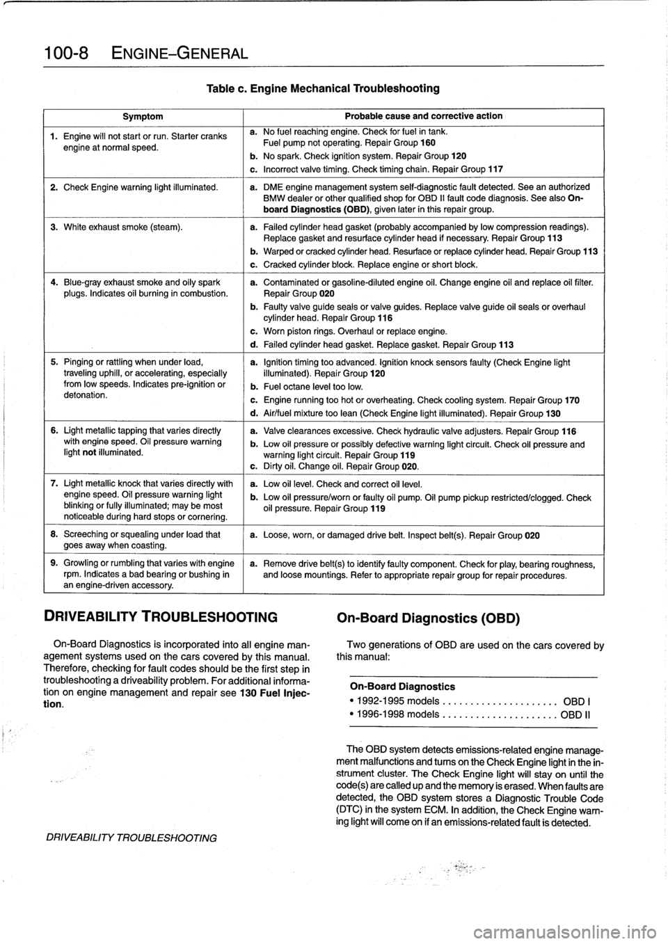
Tablec
.
Engine
Mechanical
Troubleshooting
b
.
Warped
or
cracked
cylinder
head
.
Resurface
or
replace
cylinder
head
.
Repair
Group
113
c
.
Cracked
cylinder
block
.
Replace
engine
or
short
block
.
c
.
Worn
piston
rings
.
Overhaul
or
replace
engine
.
d
.
Failed
cylinder
head
gasket
.
Replace
gasket
.
Repair
Group
113
d
.
Air/fuel
mixture
too
lean
(Check
Engine
light
illuminated)
.
Repair
Group
130
a
.
Valveclearances
excessive
.
Check
hydraulic
valve
adjusters
.
Repair
Group
116
b
.
Low
oil
pressure
orpossibly
defective
warning
light
circuit
.
Check
oil
pressure
andwarning
light
circuit
.
Repair
Group
119
c
.
Dirty
oil
.
Change
oil
.
Repair
Group
020
.
a
.
Low
oil
leve¡
.
Check
and
correct
oil
leve¡
.
b
.
Low
oil
pressure/worn
or
faulty
oil
pump
.
Oil
pump
pickup
restricted/clogged
.
Check
oil
pressure
.
Repair
Group
119
The
OBD
system
detects
emissions-related
engine
manage-
ment
malfunctions
and
tucos
on
the
Check
Engíne
lightin
the
in-
strument
cluster
.
TheCheck
Engine
light
will
stay
on
until
the
code(s)are
called
up
and
the
memory
is
erased
.
When
faulty
are
detected,
the
OBD
system
stores
a
Diagnostic
Trouble
Code
(DTC)
in
the
system
ECM
.
In
addition,
the
Check
Engine
warn-
ing
light
will
come
on
if
an
emissions-related
fault
is
detected
.
Page 59 of 759
110
Engine
Removal
and
Installation
GENERAL
.
.
.
.
.......
.
.
.
..........
.
...
110-1
Engine,
removing
and
installing
(4-cylinder
engines)
.
..
.....
..
...........
110-1
ENGINE
REMOVAL
AND
INSTALLATION
110-1
Engine,
removing
and
installing
(6-cylinder
engines)
..
...
...
..
.....
..
....
110-4
GENERAL
Some
special
tools
are
required
for
removal
and
installation
of
the
engine
.
Be
sure
to
have
the
necessary
equipment
on
hand
before
starting
thejob
.
CAUTION-
"
Engine
removal
requires
disconnecting
the
bat-
tery
.
This
may
erase
any
system
fault
code(s)
that
havebeen
stored
in
control
unit
memories
.
Check
forfault
codes
prior
to
disconnecting
the
battery
cables
.
"
If
the
Check
Engine
lightis
illuminated
with
the
engine
running,
see
100
Engine-General
for
On-Board
Diagnostics
(08D)
fault
code
infor-
mation
.
"
If
any
other
system
faults
have
been
detected,
as
indicated
by
an
illuminated
ANTI
LOCK,
SRS
or
AST
warning
light,
see
the
appropriate
repair
group
inthis
manual
or
an
authorized
BMW
dealer
for
more
information
on
fault
codes
.
ENGINE
REMOVALAND
INSTALLATION
Engine,
removing
and
installing
(4-cylinder
engines)
Cover
al¡
painted
surfaces
before
beginning
theremoval
procedure
.
Asan
aid
to
installation,
label
al¡
components,
wires,
and
hoses
before
removing
them
.
Do
not
reuse
gas-
kets,
O-rings
or
seals
during
reassembly
.
WARNING
-
Due
to
risk
of
personal
injury,
be
sure
the
engine
is
cold
before
beginning
the
removalprocedure
.
1.
Disconnect
negative
(-)
cable
from
battery
in
luggage
compartment
.
0011969
CAUTION-
Prior
to
disconnecting
the
battery,
read
the
battery
disconnection
cautions
given
at
the
front
of
this
manual
on
page
viii
.
ENGINE
REMOVAL
AND
INSTALLATION
110-1
2
.
Remove
transmission
from
car
.
See230
Manual
Transmission
or
240
Automatic
Transmission
.
3
.
Remove
enginehood
or
place
hood
in
service
positíon
.
See
410
Fenders,
Engine
Hood
.
NOTE-
tt
is
notnecessary
to
remove
the
engine
hood,
but
it
is
helpful
and
will
make
engine
removal
and
installation
easier
.
4
.
Remove
splash
guard
under
engine,
if
applicable
.
5
.
Unbolt
ignition
coil
assembly
from
bracket
on
strut
tow-er
.
Disconnect
wiring
to
ignition
cofs,
then
place
coil
assembly
on
engine
.
6
.
Disconnect
al¡
cables
and
harness
connectors
at
throt-
tle
housing
.
7
.
Unbolt
andremove
complete
air
cleaner
housing
with
mass
air
flow
sensor,
disconnecting
and
labeling
con-
nectors,
ducting
and
hoses
asnecessary
.
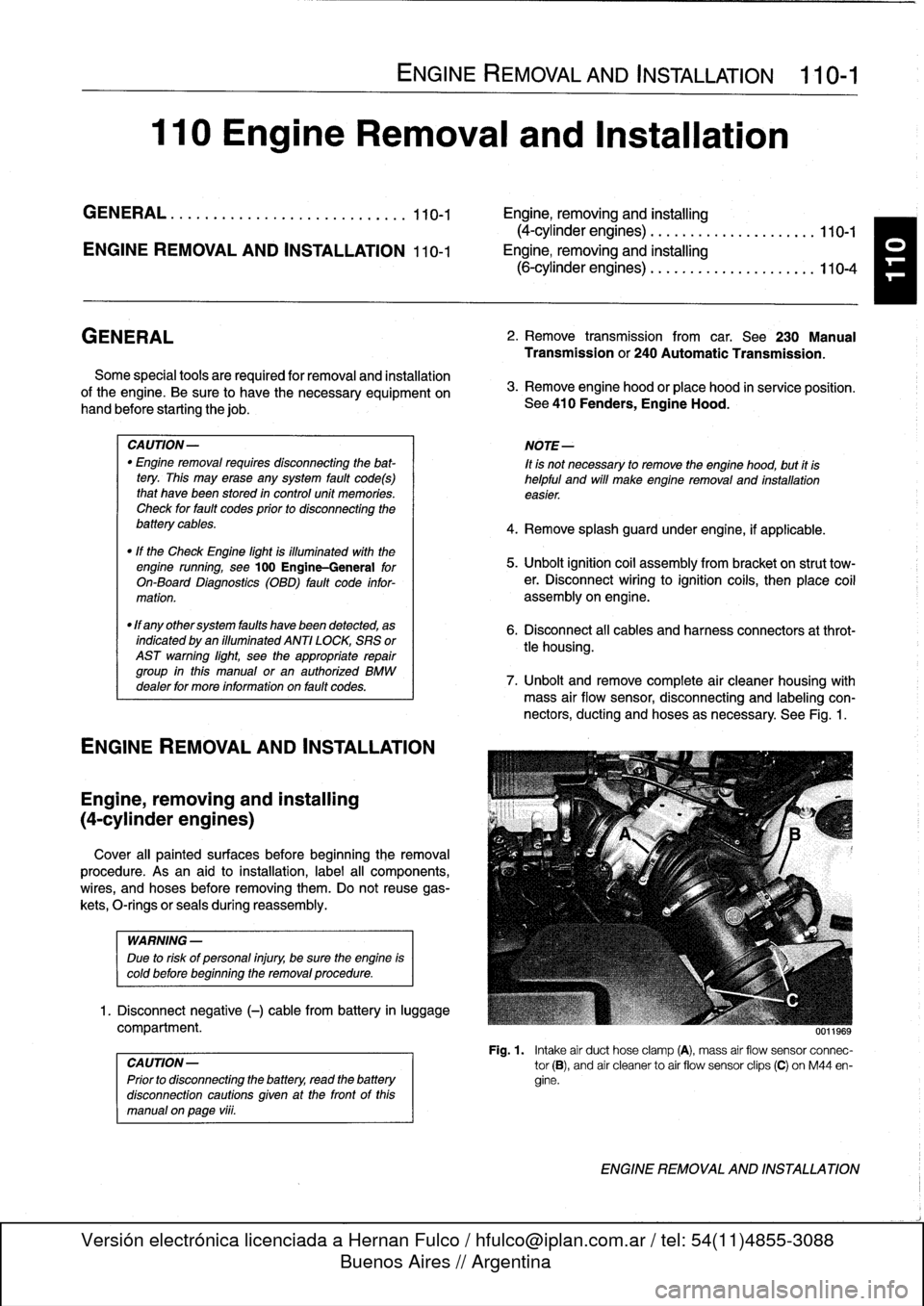
See
Fig
.
1
.
Fig
.
1
.
Intake
air
duct
hose
clamp
(A),
mass
air
flow
sensor
connec-
tor
(B),
and
air
cleanerto
air
flow
sensor
clips
(C)
on
M44
en-
gine
.
ENGINE
REMOVAL
AND
INSTALLATION
Page 61 of 759
14
.
Unbolt
power
steering
fluid
reservoir
from
íts
mounting
bracket
.
Use
stiff
wire
to
hang
reservoir
to
one
side
.
Do
not
disconnect
fluid
lines
.
15
.
Remove
power
steering
pump
drive
belt
and
remove
pump
from
its
mounting
bracket
.
Use
stiff
wire
to
hang
pump
from
body
.
16
.
On
cars
with
automatic
transmission
remove
front
and
rear
brackets
holding
automatic
transmission
cooler
linesto
engine
.
17
.
Remove
A/C
compressor
from
its
mounting
bracket
without
disconnecting
any
refrigerantlines
.
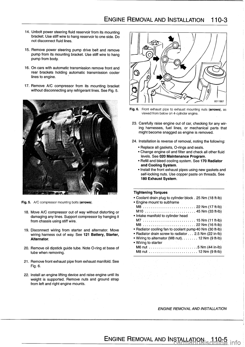
See
Fig
.
5
.
ENGINE
REMOVAL
AND
INSTALLATION
110-
3
21
.
Remove
front
exhaust
pipefrom
exhaust
manifold
.
See
Fig
.
6
.
22
.
Install
an
engine
lifting
device
and
raise
engine
until
its
weight
is
supported
.
Remove
nuts
and
ground
strap
from
left
and
right
engine
mounts
.
0011967
Fig
.
6
.
Front
exhaustpipe
to
exhaust
mounting
nuts
(arrows),
as
viewed
from
below
on
4-cylinder
engine
.
23
.
Carefully
raíse
engine
out
of
car,
checking
for
any
wir-
ing
harnesses,
fuel
lines,
or
mechanical
parts
that
might
become
snagged
as
engine
is
removed
.
24
.
Installation
is
reverse
of
removal,
noting
the
following
:
"
Replace
all
gaskets,
O-rings
and
seals
.
"
Change
engine
oil
and
filter
and
check
al¡
other
fluid
levels
.
See020
Maintenance
Program
.
"
Refill
and
bleed
cooling
system
.
See
170
Radiator
and
Cooling
System
.
"
Insta¡¡
the
front
exhaust
pipes
using
new
gaskets
and
self-locking
nuts
.
Use
copper
pasteon
threads
.
See
180
Exhaust
System
.
Tightening
Torques
"
Coolant
drain
plug
to
cylinder
block
.
25
Nm
(18
ft-Ib)
Fig
.
5
.
A/
C
compressor
mounting
bolts
(arrows)
.
"
Engine
mount
to
subframe
M8
......:...
..
..
..
......,:..
22
Nm
(17
ft
-
1b)
,
18
.
Move
A/C
compressor
out
of
way
without
distorting
or
M10
.
...
.
..
...
.
.
...........
45
Nm
(33
ft'-Ib)
damaging
any
lines
.
Support
compressor
by
hanging
it
"
Intake
manifold
to
cylinder
head
from
chassis
using
stiff
wire
.
M7
.....
.
..
...
..
..
...........
15
Nm
(11
ft-Ib)
M8
...
.
.
.
..
..
...
..
...........
22
Nm
(16
ft-Ib)
19
.
Disconnect
wiring
from
starter
and
alternator
.
Move
`
"
Radiator
cooling
fan
to
coolant
pump40
Nm
(30
ft-Ib)
wiring
harness
out
of
way
.
See
121
Battery,
Starter,
"
Radiator
drain
screw
to
radiator
...
2
.5
Nm
(22
in-lb)
Alternator
.
"
Wiring
to
alternator
(M8
nut)
........
12
Nm
(9
ft-1b)
"
Wiring
to
starter
20
.
Remove
oil
dipstick
guide
tube
.
Note
O-ring
at
base
of
M6
nut
..
.
..
..
...
..
...........
.
:5
Nm
(44
in-lb)
tube
when
removing
.
M8
nut
..
.
..
..
...
..
............
12
Nm
(9
ft-Ib)
ENGINE
REMOVAL
AND
INSTALLATION